

Page 1
INSTALLATION
www.collegehillshonda.com
INSTRUCTIONS
Accessory Application Publications No.
AIR CONDITIONER
2-DOOR DX
4-DOOR DX
2006 CIVIC
2- AND 4-DOOR
AII 31246-31447
Issue Date
NOV 2005
TOOLS AND SUPPLIES REQUIRED
Phillips screwdrivers [1 stubby and 1 extra long
(150mm or 6" shaft)]
Small flat screwdriver
Feeler gauge set
Ratchet with extensions (wobble or universal extension
and 8 mm, 10 mm and 12 mm sockets
Combination wrench (10 mm, 19 mm, 22 mm, 24 mm,
and 27 mm)
Belt tension release tool #YA9317
Diagonal cutters
Utility knife
Clip remover tool
Torque wrench
M5 bolts
M6 bolts/nut
M8 bolts
INSTALLATION INSTRUCTIONS
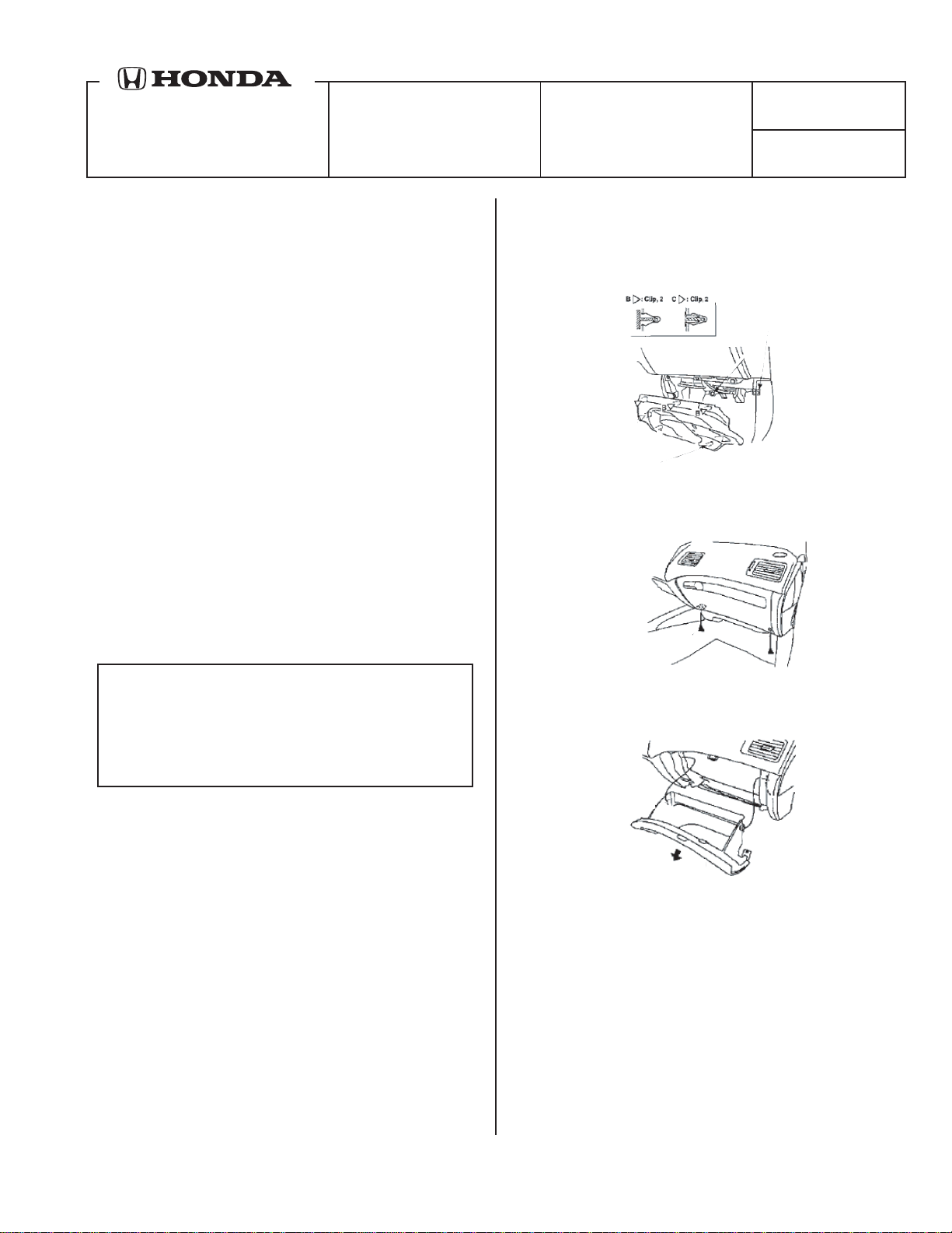
4. Inside the passenger's compartment, remove the
passenger dashboard undercover and then the
glove box (two 8 mm washer-bolts for the hinges,
then open the glove box to remove).
UNDERCOVER
Customer Information: The information in this
installation instruction is intended for use only by
skilled technicians who have the proper tools,
equipment, and training to correctly and safely add
equipment to your vehicle. These procedures should
not be attempted by “do-it-yourselfers.”
NOTE: Be careful not to damage the body paint finish.
1. Write down the radio station presets.
2. With the ignition switch on, turn on the windshield
wipers. When the wipers reach the top position
turn off the ignition switch.
3. Disconnect the negative cable from the battery.
PRELIMINARY
© 2005 American Honda Motor Co., Inc. - All Rights Reserved. AII 31246-31447 (0511) 1 of 12
Page 2
PRELIMINARY
3
Page 3
PRELIMINARY
2
Page 4

Group A
79601-S5A-003
80290-S5D-A01
80210-SD5-G03
80210-S5D-G02
80560-S5A-941
80271-S5A-000
80295-S5D-A01
Group Part P/N Qty
Drain hose clip 53747-SA5-003 1
A/C button 79601-S5A-003 1
A
Evaporator 80210-S5D-G03 1
Drain hose 80271-S5A-000 1
Dust and pollen filter A 80290-S5D-A01 1
Dust and pollen filter B 80295-S5D-A01 1
Evaporator sensor 80560-S5A-941 1
Wire ties 38221-SW5-300 2
Condenser fan assembly 38605-PMM-A12 1
Compressor 38800-PLM-A12 1
B
Compressor belt 38920-PLR-004 1
Heat insulator 38935-PLM-A00 1
Condenser assembly 80100-S5A-T01 1
Right condenser bracket 80107-S5A-000 1
Left condenser bracket 80108-S5A-000 1
Suction line 80311-S5D-A12 1
Discharge hose 80315-S5A-013 1
A/C suction line and receiver line B 80320-S5D-A12 1
Condenser line 80331-S5D-A11 1
Receiver line 80341-S5D-A02 1
Receiver 80350-S5D-A01 1
Suction hose clamp A 80360-S5A-A00 1
Suction hose bracket 80361-S5A-A00 1
Suction line bracket 80363-S5A-A01 1
Receiver line clip A 80381-S5A-A01 1
Receiver line clip B 91548-S5A-003 1
A/C wire harness 80460-S5A-A00 1
Flange bolts, 8 x 100 mm 90023-P2A-000 4
Ground bolt, 6 x 12 mm (brass-colored) 90153-SE0-003 1
Paint cutting nut, 6 mm (yellow-tinted) 90361-SV4-003 3
Washer-bolt, 6 x 12 mm (yellow-tinted) 93403-06012-08 1
Washer-bolts, 6 x 16 mm (gray-colored) 93403-06016-05 7
Flange bolts, 6 x 12 mm (yellow-tinted) 95701-06012-08 2
Flange bolts, 6 x 25 mm (yellow-tinted) 95701-06025-08 4
Flange bolt, 6 x 30 mm (yellow-tinted) 95701-06030-08 1
Power relay (4P) 39794-S0K-A01 2
Information label (Canada) 80050-SP0-000 1
C
Information label (USA) 80050-SR3-H00 1
A/C kit identification label (USA) 8005X-S5D-A24 1
53747-SA5-003
Group C
39794-S0K-A01 8005X-S5D-A21 80050-SR3-H00 80050-SP0-000
8005X-SD5-A24
AIR CONDITIONER SYSTEM
PRELIMINARY
Page 5

Group B
90023-P2A-000
(Yellow-tinted)
95701-06030-08
93403-06016-05
(Gray-colored)
38800-PLM-A12
38800-PLM-A02
(Yellow-tinted)
90361-SV4-003
80311-S5D-A12
(Yellow-tinted)
95701-06025-08
38800-PLM-A12
90361-SV4-003
(Yellow-tinted)
80341-S5D-A02
80341-S5D-A11
80341-S5D-A02
(Yellow tinted)
95701-06012-08
80320-S5D-A12
93403-06016-05
(Gray-colored)
80361-S5A-A00
(Brass-colored)
90153-SE0-003
80363-S5A-A01
38935-PLM-A00
(Yellow-tinted)
93403-06012-08
80381-S5A-A01
38920-PLR-004
80360-S5A-A00
80387-SM4-A01
91548-S5A-003
91548-S5A-003
80460-S5A-A00
(Gray-colored)
93403-06016-05
(Yellow-tinted)
95701-06025-08
38221-SW5-300
38221-SW5-300
08F13-S8410013
80331-S5D-A11
93403-06016-05
(Gray-colored)
80315-S5A-013
93403-06016-05
(Gray-colored)
80350-S5D-A01
(Yellow-tinted)
95701-06025-08
80100-S5A-T01
80100-S5A-T01
80100-S5A-003
38605-PMM-A12
38605-PMM-A12
38605-PMM-A11
80107-S5A-000
93403-06016-05
(Gray-colored)
80108-S5A-000
PRELIMINARY
Page 6

5. Remove the steel glove box lower frame (two
washer-bolts.
8. Remove the blower motor assembly:
GLOVE BOX
LOWER FRAME
6. Using diagonal cutters (and/or a utility knife), cut
out the dashboard-link at the glove box area.
7. Remove the passenger's heater duct (one hex
screw and two self-tapping screws), and remove
the harness connector clip.
• Remove the three nuts, one flange bolt, and
the three washer-screws (black).
• Disconnect the white 14-pin connector at the
top of the blower motor, the white 2-pin
connector at the bottom, and the green 4-pin
recirc motor connector on the right side of the
motor.
• Pull the blower motor out past the three studs,
and tilt the assembly down. Rotate the
assembly toward the center of the vehicle and
down to remove it.
9. Remove the evaporator housing cover (nine
screws), and disconnect the 4-pin power transistor
connector. To reach the forward middle screw, you
will need a long Phillips #2 screwdriver
(150 mm/6" shaft).
PRELIMINARY
6 of 12 AII 31246-31447 (0511) © 2005 American Honda Motor Co., Inc. - All Rights Reserved.
Page 7

10. Remove and discard the evapo-dummy.
11. Next to the evaporator housing against the front
bulkhead, locate and remove the floor insulator
plug, which reveals a rubber plug in the front
bulkhead. Remove the rubber plug by pushing on
the plug. Discard the floor insulator plug and the
rubber plug.
12. Below the evaporator housing, under the carpet,
locate and remove the floor insulator plug for the
drain hose. Discard the insulator plug. Remove
and discard the rubber plug in the floor.
13. Get the drain hose and the drain hose clip from
the kit. Attach the drain hose clip to the drain hose
with the tab ends at the white line on the hose.
14. On the bottom of the evaporator housing, remove
and discard the drain-spout plug. Install the drain
hose with the clamp to the drain-spout, and route
the opposite side out through the hole in the floor.
Seat the grommet from the drain hose into the
hole in the floor. Check that the hose is not
kinked.
15. Get the evaporator and the lower evaporator cover
from the kit. Assemble the evaporator and the
lower evaporator cover, and ensure that the temp
sensor clip(s) are secure in the fins. Insert the
evaporator & cover assembly into the evaporator
housing until it bottoms out. Assure that the
expansion valve (still with cover) is aligned in the
center of the hole in the bulkhead.
16. Route the temperature sensor wire from the
evaporator rearward, and reinstall the evaporator
cover with the temperature sensor wire routed
through the notch in the cover. Reattach the 4-pin
power transistor connector to the evaporator
housing cover.
17. Locate the connector for the evaporator
temperature sensor, blue-taped to the vehicle
harness. Remove the blue tape to free the
connector. Connect the temperature sensor, and
clip the connector to the hole in the evaporator
cover.
18. Get the pollen filter and cover from the kit.
Remove and discard the cover from the blower
motor (two clips). Install the pollen filter and cover
into the blower motor. Observe the arrows on the
filter and cover to install properly.
19. Reinstall the blower motor, and reattach the 14-pin
wire harness blower motor harnesses and clip to
the blower motor.
PRELIMINARY
20. Reinstall the passenger heater duct, and install
the wire harness clip.
21. Reinstall passenger dashboard under cover.
22. Reinstall the glove box lower frame A and the
glove box.
© 2005 American Honda Motor Co., Inc. - All Rights Reserved. AII 31246-31447 (0511) 7 of 12
Page 8

23. Get the MAX A/C button and the A/C button from
the kit. Below the radio, remove and discard the
dummy buttons from the heater control panel.
NOTE: To prevent damage to the heater control
panel bezel, insert a 0.5 mm flat feeler gauge
under the dummy button and leverage the small
flat screwdriver to remove the dummies on the
surface of the gauge and not on the surface of the
bezel. Snap the MAX A/C button and the A/C
button into the heater control panel.
27. Remove the front bumper, two screws and twleve
clips.
SCREWS
• Remove the radiator cover (four clips).
• On each side, remove the screw "A" from the
fender well area.
Installing the Engine Compartment Parts
(Compressor and Belt, Condenser, Hoses and
Pipes)
24. Remove the right and left cowl cover end pieces
by removing the weather strip from each end
piece, and pulling up on each cover to release the
5 tabs.
25. Under the hood, remove the cowl cover (three
clips, and disconnect the windshield washer
hose).
26. Remove the cowl cover place (9 bolts).
PRELIMINARY
• Remove the clips along the bottom of the front
bumper
• Remove the 2 bumper (grille) clips from the
front bulkhead.
• With the help of an assistant, pull out on each
side to remove the retaining tabs. Remove the
front bumper and set it aside on a blanket.
28. Remove the power wires from the alternator.
Disconnect the connector from the alternator.
29. Using the belt tension tool (special tool #YA9317),
release the belt tension and remove the belt from
the alternator.
30. Remove the alternator (two 8 mm bolts). Be
careful not to loosen the recessed nut.
31. Remove and discard the power steering/alternator
belt.
8 of 12 AII 31246-31447 (0511) © 2005 American Honda Motor Co., Inc. - All Rights Reserved.
Page 9

32. Remove the two brackets that secure the front of
the radiator, and remove the two bolts from the
radiator filler neck. Carefully pull up and out on the
right side of the radiator, away from the radiator
bulkhead, to lower the compressor in place and to
ease the installation of the hoses.
33. Remove the dummy washer-bolts from the
compressor bracket. Get the compressor, the two
M8 x 65 mm bolts, and the two M8 x 80 mm bolts
from the kit.
34. Place the compressor into position on the
compressor bracket by engaging the pins on the
compressor to the cutouts in the bracket. Install
the two upper M8 x 80 mm bolts and the two lower
M8 x 65 mm bolts, and securely tighten the bolts.
36. Get the suction hose from the kit. Remove and
discard the pipe cover and the M6 bolt from the
compressor. Remove and discard the suction
hose cover. Attach the suction hose to the
compressor using the M6 x 25 mm flange bolt
from the kit.
37. Reinstall the alternator and wiring. Remove the
blind plug from the connector on the bracket, and
insert the coupler from the compressor wire
harness.
38. Get the belt from the kit. Route the belt around all
the pulleys, saving the alternator pulley for last.
Using the belt tension release tool, rotate the tool
counterclockwise, and install the belt over the
alternator pulley. Check to make sure that the belt
is properly aligned on each pulley.
35. Get the discharge hose from the kit. At the front
right side of the vehicle, route the hose end of the
discharge hose on the right side of the radiator
and to the compressor. Remove the 6 mm nut and
the discharge port cover from the compressor.
Discard the port cover, but save the 6 mm nut.
Remove the pipe cover from the end of the
discharge hose, and attach the discharge hose to
the compressor, reusing the M6 nut.
PRELIMINARY
39. Remove the temp sensor coupler with cover,
clipped to the left frame, and install the receiver
pipe clip from the kit in the square hole in the
frame.
© 2005 American Honda Motor Co., Inc. - All Rights Reserved. AII 31246-31447 (0511) 9 of 12
Page 10

40. Install the other receiver pipe clip from the kit into
the hole in the ABS bracket.
41. Get the receiver pipe from the kit. From inside the
engine compartment, route the receiver pipe on
the right side of the radiator, and fit the receiver
pipe into the clip in the frame rail to hold the pipe.
45. At the condenser, remove the caps from the
discharge hose and receiver pipe, and remove the
caps from the condenser. Lightly oil the O-rings
with PAG oil, insert the discharge hose into the
condenser, and secure with the 6 mm x 25 mm
bolt. Attach the bracket from the discharge hose
to the mount on the condenser using a 6 mm x
16 mm washer bolt and torque to 7.2 lb·ft. Insert
the receiver pipe into the condenser and secure
with the 6 mm x 25 mm bolt and torque to 7.2
lb·ft.
42. Reinstall the radiator and the filler neck.
43. Get the condenser, the condenser brackets, the
two 6 mm x 30 washer-bolts and the two 6 mm x
12 bolts (black) from the kit. Move the discharge
hose and the receiver pipe out of the way, and
insert the condenser from the bottom up between
the bumper and the radiator. Seat the rubber
grommets from the condenser into the holes in the
lower frame.
NOTE: To prevent damage to radiator fins while
installing the condenser, place the rectangular
piece of cardboard from the kit against the
radiator.
44. Install the right and left condenser brackets with
the 6 mm x 30 mm washer-bolts to front bulkhead
and to the condenser with the 6 mm x 12 mm
bolts then torque to 7.2 lb·ft. Remove the
cardboard between the radiator and the condenser.
PRELIMINARY
46. On the left side of the engine compartment below
6 mm Bolt
6 mm Bolt
the right headlight, locate the pressure sensor
connector blue taped to the vehicle harness.
Remove the blue tape to free the connector. Plug
the connector onto the pressure sensor mounted
on the receiver pipe.
10 of 12 AII 31246-31447 (0511) © 2005 American Honda Motor Co., Inc. - All Rights Reserved.
Page 11

47. Remove the cap from the expansion valve. Get
the stud bolt from the kit, and secure its short M6
side to the expansion valve.
48. Get pipe stay A and B from the kit. Secure pipe
stay A to the rear of the engine mount vibration
bracket with one 6 mm x 16 mm washer-bolt and
torque to 7.2 lb·ft. Secure stay B to the front of
the engine mount vibration bracket with one 6 mm
x 16 mm washer-bolt and torque to 7.2 lb·ft.
Attach the plastic clip to stay B.
50. Remove the caps from the suction hose and
receiver pipe coupling and lightly oil the O-rings
with PAG oil. Remove the caps from the mating
coupling of the aircon pipe, and connect the
couplings hand tight. Secure the couplings, for the
receiver pipe with a 17 mm & 19 mm combination
wrench and for the suction coupling with a 24 mm
and 27 mm combination wrench. Do not over
tighten.
49. Get the aircon pipe from the kit. Remove the cap
from the flange end of the aircon pipe and lightly
oil the O-rings with PAG oil. Guide the flange end
of the aircon pipe over the stud bolt of the
expansion valve and push the O-ring fittings into
the expansion valve. Secure the flange with the
M6 nut from the kit.
PRELIMINARY
51. Get pipe stay A and B and the clip from the kit.
Secure pipe stay A to the rear of the engine mount
vibration bracket with one 6 mm x 16 mm washer
bolt. Attach the clip to stay B and secure stay B
to the front of the engine mount vibration bracket
with one 6 mm x 16 mm washer bolt and torque to
7.2 lb·ft. Attach the plastic clip on the aircon pipe
to stay A through the rectangular hole.
52. Get the clamp from the kit, attach it to the suction
hose and then to pipe, stay B with one 6 mm x 16
mm washer bolt and torque to 7.2 lb·ft. Attach the
receiver pipe to the clip on stay B.
© 2005 American Honda Motor Co., Inc. - All Rights Reserved. AII 31246-31447 (0511) 11 of 12
Page 12

53. Get the AC clutch relay from the kit. Insert the
relay in its slot in the fuse box.
56. Evacuate the system for at least 15 minutes.
57. Reset radio station presets.
58. Install the labels under the hood at a cleaned
location near the emission label.
• For USA Registered Vehicles: Aircon INFO Label and either of the A/C Kit I.D.-Labels
• For USA Registered Vehicles: USA A/C Kit
Identification Label
For 4-Door Label displaying 80000-SNA-Y00
For 2-Door Label displaying 80000-SVA-Y00
• For Canada Registered Vehicles: Aircon R134a Label
NOTE: If after 15 minutes the pressure has not
reached down to 93.3kPa (700 mmHg, 27.6InHg),
there is probably a leak in the system. Using a leak
detector (Honda Tool & Equipment YGK-H-10PM) find
and repair the leak.
54. Reinstall all removed parts (radiator cover,
bumper, cowl plate, cowl cover and windshield
washer hose, battery cable). Observe illustration
below for proper orientation of radiator cover.
PRELIMINARY
55. Hook up the system to an aircon charging station.
59. Charge the system and check system
performance. Be sure to add the same amount
of NEW refrigerant oil to the system as that was
removed during the evacuation procedure(s).
60. Refrigerant leak test.
61. System performance test. With the charge station
hoses connected, run the A/C system
performance Test per the 2006 Civic Service
Manual.
12 of 12 AII 31246-31447 (0511) © 2005 American Honda Motor Co., Inc. - All Rights Reserved.
 Loading...