

Page 1
STACK-ON UNIT
Sharp edges may cause injury. Take care
when handling metal parts.
IMPORTANT
Assembly hardware is located in a padded
pack. Be sure to locate hardware pack
before discarding any packaging materials.
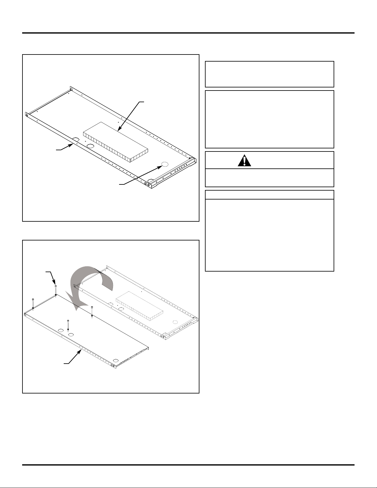
Pieces of honeycomb cardboard glued to
interior walls of end panels (refer to
Illustration 1) is designed to reduce unwanted sound caused by ordinary use of stackon unit. Do not remove this sound deadening material.
WARNING
Read all instructions and review illustrations before installing.
Tools required for assembly:
Phillips screwdriver Mallet
9
/64" Allen wrench (provided)
This assembly includes:
(1) RH end panel (1) LH end panel
(2) End panel cover (1) Back
(1) Bottom shelf (1) Top shelf
(2) Mounting bracket (4) Machine screw
(12) Sheet metal screw (2) Washer plate
(12) Grommet half (4) Hex nut
(1) 9/64" Allen wrench
Installation:
1. Refer to Illustration 1. Identify the right-hand
end panel by locating the RH label affixed to
the interior wall of the end panel.
2. Refer to Illustration 2. Lay right-hand end
panel, flat surface up, onto a piece of cardboard or a carpeted surface.
Use the Phillips screwdriver to install four
sheet metal screws (from hardware pack)
into holes in flat surface of end-panel. Do not
fully tighten screws. Leave approximately an
1
/8" gap between wall of end panel and head
of screw.
3. Repeat Steps 1 and 2 for left-hand end
panel.
343-0140
SIDE 1 OF 6 (7/00)
INSTALLATION
INSTRUCTIONS
RH
Illustration 1
RH
Illustration 2
Sound deadening
material (do not
remove)
Right-hand
label
Right-hand
end panel
End panel
Sheet metal
screw
Page 2
STACK-ON UNIT
343-0140
SIDE 2 OF 6 (7/00)
Illustration 3
Illustration 4
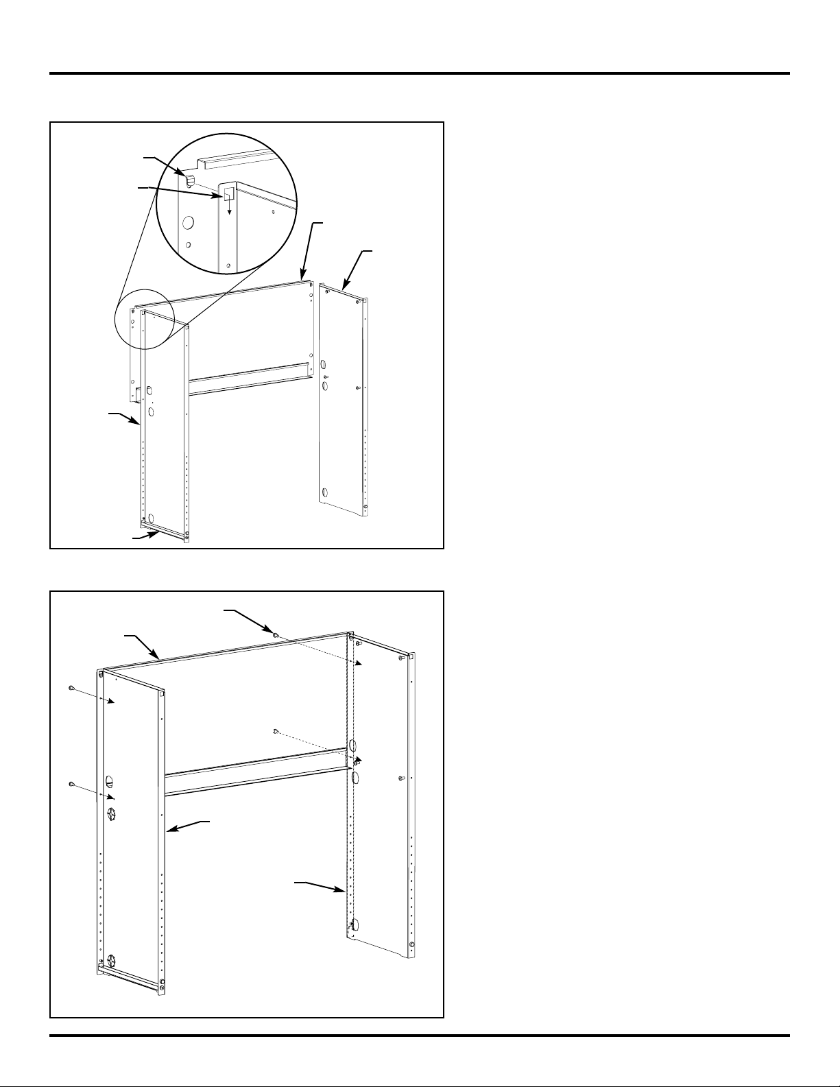
4. Refer to Illustration 3. Use an assistant to position
end panels. With panel brackets down and large
square cut-outs facing toward back, position end
panels with flat surface facing each other and
approximately the width of the back apart.
Locate tabs in upper corners of back. Hook tabs
into large square cut-outs at top rear edge of each
end panel.
5. Refer to Illustration 4. Use the Phillips screwdriver
to install four sheet metal screws (from hardware
pack) through holes in back and into holes in rear
edge of end panels. Fully tighten screws.
Tab
Back
Right-hand
end panel
Left-hand
end panel
Large square
cut-out
Panel bracket
Sheet metal screw
Left-hand
end panel
Right-hand
end panel
Back
Page 3
STACK-ON UNIT
343-0140
SIDE 3 OF 6 (7/00)
Illustration 5
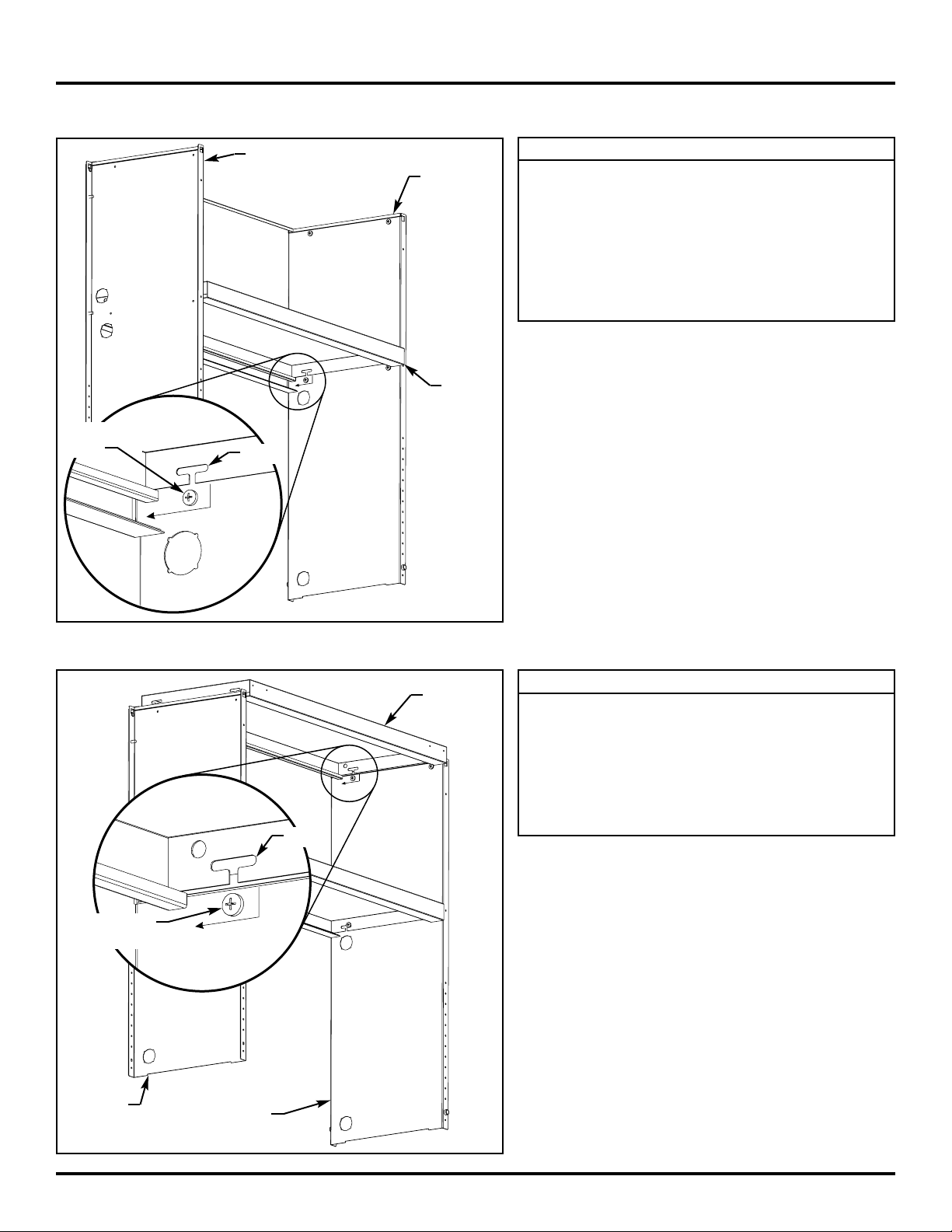
6. Refer to Illustration 5. With flat surface facing up,
insert bottom shelf between end panels just above
bottom set of sheet metal screws (installed into flat
surface of each end panel).
Locate two notches cut into each side wall of bottom shelf. Insert end panel sheet metal screws into
bottom shelf notches and push shelf rearward.
Ensure sides of bottom shelf are between the
heads of the sheet metal screws and the end panels.
Do not tighten sheet metal screws at this time.
Illustration 6
7. Refer to Illustration 6. With flat surface facing up,
insert top shelf between end panels just above top
set of sheet metal screws (installed into flat surface
of each end panel).
Locate two notches cut into each side wall of top
shelf. Insert end panel sheet metal screws into top
shelf notches and push shelf rearward. Ensure
sides of top shelf are between the heads of the
sheet metal screws and the end panels.
8. Use the Phillips screwdriver to fully tighten all sheet
metal screws securing top and bottom shelves to
end panels.
NOTE
The top shelf is designed for either a flipper door or
non-flipper door application. If installing flipper
door(s), install top shelf with door mounting holes
(along front edge of top shelf) facing out. If flipper
door(s) are not being installed, install top shelf with
door mounting holes facing towards rear of stackon unit.
NOTE
The bottom shelf is designed for either a flipper
door or non-flipper door application. If installing flipper door(s), install bottom shelf with notch(s)
(along front edge of bottom shelf) facing out.
Notch(s) accommodate the flipper door lock mechanism. If flipper door(s) are not being installed,
install bottom shelf with notch(s) facing toward rear
of stack-on unit.
Bottom
shelf
Notch
Sheet metal
screw
Right-hand
end panel
Left-hand
end panel
Top shelf
Notch
Sheet metal
screw
Right-hand
end panel
Left-hand
end panel
Page 4
STACK-ON UNIT
343-0140
SIDE 4 OF 6 (7/00)
Illustration 7
Illustration 8
Illustration 9
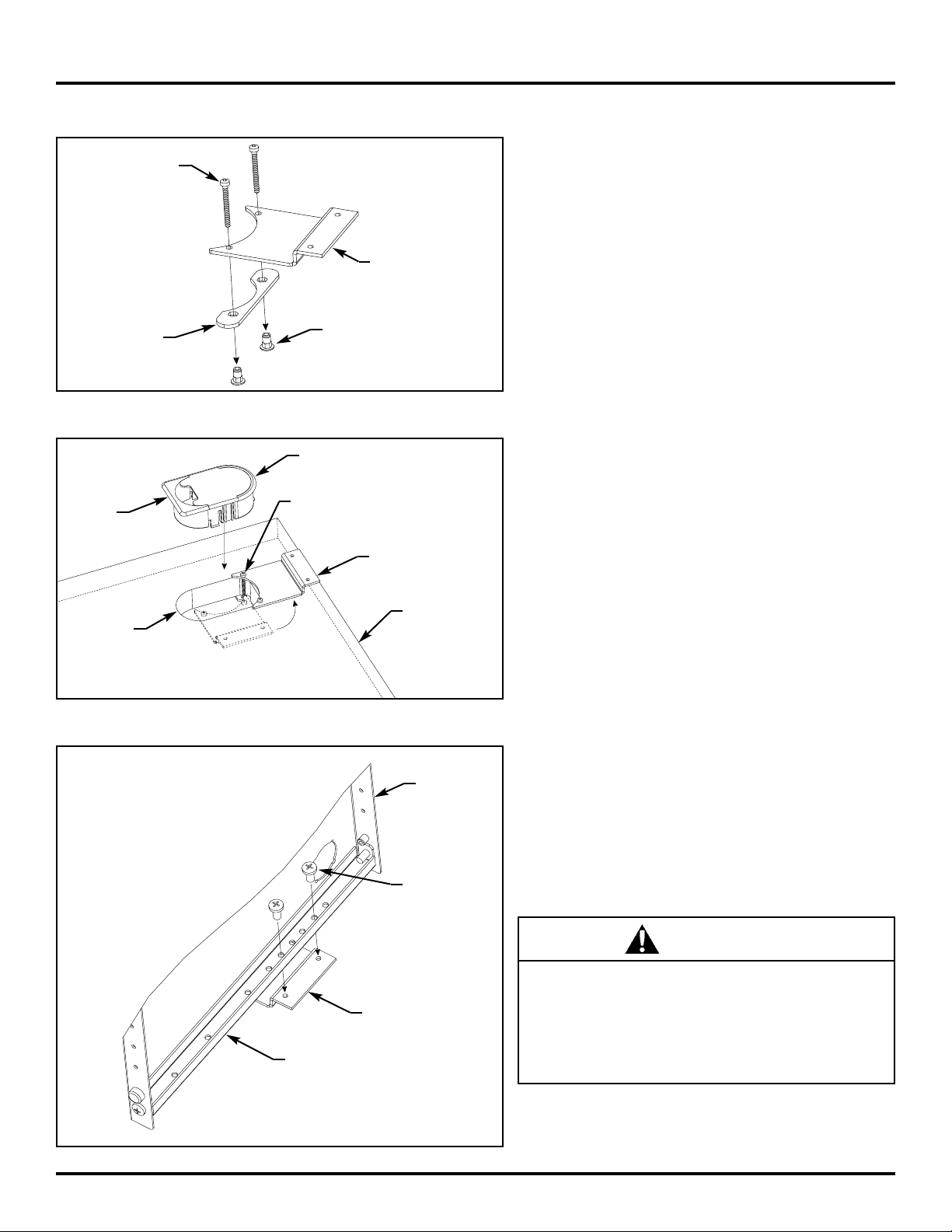
9. Refer to Illustration 7. Loosely assemble a mounting bracket, two machine screws, a washer plate,
and two hex nuts (all from hardware pack).
Repeat this procedure to assemble a second
mounting bracket assembly.
10. Refer to Illustration 8. If necessary, remove grommet from main unit worksurface grommet hole.
Install mounting bracket assembly into the worksurface grommet hole as shown. Pivot mounting
bracket against side edge of grommet hole. Ensure
washer plate is below the main unit worksurface.
With straight edge facing away from mounting
bracket (toward center of worksurface), (re)install
grommet into grommet hole.
Use the
9
/64" Allen wrench (from hardware pack) to
fully tighten machine screws.
Repeat this procedure to install remaining mounting
bracket assembly onto opposite end of main unit
worksurface.
11. Refer to Illustration 9. Use two or more people to
set assembled portion of stack-on unit upright onto
main unit. Position rear edge of end panels along
rear edge of worksurface and align holes in panel
bracket with holes in mounting bracket.
Use the Phillips screwdriver to install two sheet
metal screws (from hardware pack) through each of
the panel brackets and into mounting brackets.
Fully tighten screws.
To prevent stack-on unit from tipping over, it is
extremely important that screws securing end
panels to mounting brackets be tight. Failure to
follow this warning or improper installation of
stack-on unit can result in severe personal injury
or property damage.
WARNING
Machine screw
Hex nut
Mounting bracket
Washer plate
Grommet
Machine screw
Mounting bracket
assembly
Main unit
worksurface
Grommet
hole
Straight
edge
End panel
Panel bracket
Sheet metal
screw
Mounting bracket
Page 5
STACK-ON UNIT
343-0140
SIDE 5 OF 6 (7/00)
Illustration 10
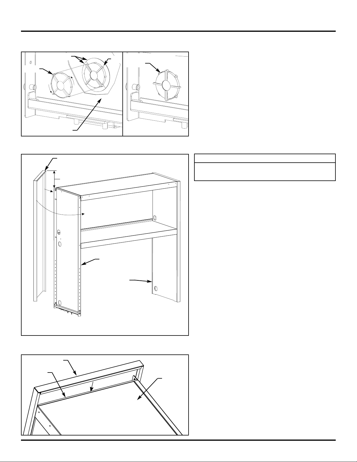
12.Refer to Illustration 10. Install wire management
grommets (from hardware pack), in three locations,
on each end panel. Place tab of each grommet half
into grommet hole notch. Twist whole grommet
1
/8"
turn (or 45°) to lock grommet in place.
Refer to Illustration 11 for installed position.
Illustration 13
Illustration 11
13.Refer to Illustration 12. With top of end panel cover
approximately 6" above top of end panel, position
rear edge of end panel cover over rear edge of end
panel.
Pivot front edge of end panel cover toward front
edge of end panel.
Carefully press front edge of end panel cover overtop the front edge of end panel until end panel
cover snaps into place.
14.Refer to Illustration 13. Slide end panel cover down
until bottom edge of end panel cover rests against
main unit worksurface. Ensure top edge of end
panel cover inserts into channel along top edge of
stack-on unit.
15.Repeat Steps 13 and 14 to install second end panel
cover over remaining end panel.
16. If installing flipper doors, refer to the Flipper Door
Installation Instructions to install doors now.
Illustration 12
NOTE
End panel covers are interchangeable. Each end
panel cover will fit either end panel.
Left-hand end panel
Grommet half
Grommet in installed
position
Notch
Tab
~
End panel cover
End panel cover
Channel
Top of
stack-on
unit
Left-hand
end panel
Right-hand
end panel
Approx. 6"
~
Page 6
STACK-ON UNIT
343-0140
SIDE 6 OF 6 (7/00)
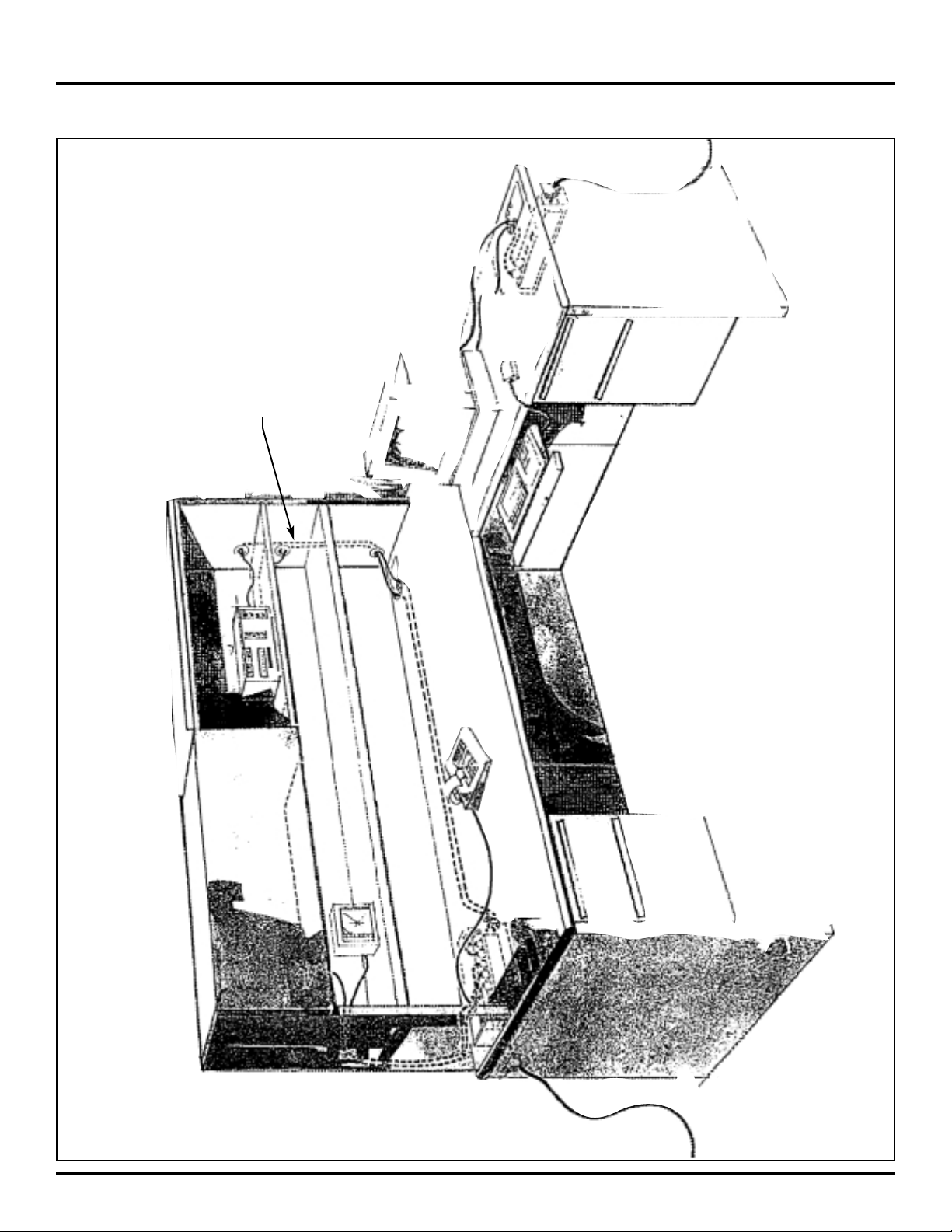
Illustration 14. Typical Wire Management:
Wires can be routed to shelves via a
hidden channel in end panels.
 Loading...