

Page 1

BOOKCASE
INSTALLATION IINSTRUCTIONS
Wood products are heavier then they
appear and may be hard to control when
moving. Use two or more people when
moving wood products or severe personal injury may result.
Heavy panels can pinch or crush fingers.
Do not place fingers between or under
panels during assembly.
To prevent the possibility of serious eye
injury, always wear eye protection when
hammering.
WARNING
Read all instructions and review illustrations before installing.
Tools required for assembly:
Phillips screwdriver
Hammer
Level
Tape measure
Illustration 1
Illustration 2
Bookcase Assembly:
242-6941E
SIDE 1 OF 6 (4/01)
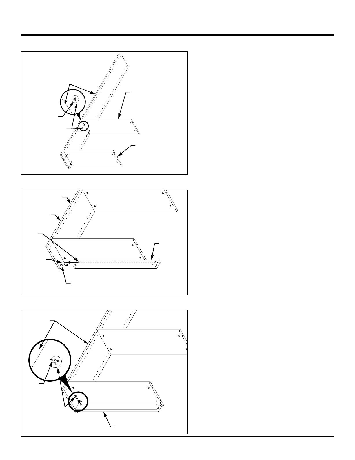
1. Refer to Illustration 2. Lay end panels, with
holes up, on cardboard or a carpeted surface.
2. Refer to Illustration 2. Use the Phillips
screwdriver to install cam bolts (from hardware pack) into locations shown. Tighten
cam bolts until cam bolt shoulder is flush
against surface of end panel.
Use the hammer to install a dowel (from
hardware pack) onto each end panel as
shown.
3. Refer to Illustration 3. On right end panel,
position bottom shelf and (if 60" or larger
bookcase) center shelf onto cam bolts.
Ensure unfinished edge of each shelf faces
rear edge of right end panel.
NOTE
Installation of a center/bottom shelf and shelf
hardware (cam bolts and cam connectors) in
the center position is required on 60" and
taller bookcases only. Illustrations show
assembly of 60" bookcases. Do not install
center shelf and center shelf hardware onto
bookcases smaller than 60".
Back Panel End Panel
Adjustable
Shelf
Bottom/
Center Shelf
Kickplate
Dowel
Leveling
Glide
Glide
Insert
Cam
Bolt
Cam
Connector
Connector
Cover
Nail
Shelf
Pin
Cam bolt
Shoulder
Dowel
End
panel
End panel
Center position - install
on a 60" or taller bookcase only.
Top Shelf
Illustration 3
Rear edge
of right
end panel
Unfinished
edge
Cam bolt
Center position install on a 60"
or taller bookcase only.
Bottom
position
NOTE
Once hardware is installed onto the end panels they become handed. Each end panel will
now be identified as the right or left end panel.
Page 2
BOOKCASE
242-6941E
SIDE 2 OF 6 (4/01)
Illustration 4
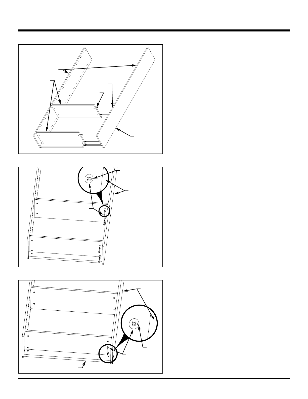
4. Refer to Illustration 4. With arrows facing the right
end panel, install cam connectors (from hardware
pack) into holes along lower edge of each shelf as
shown. Use the Phillips screwdriver to tighten cam
connectors. Turn cam connectors clockwise to
tighten.
Illustration 5
Illustration 6
5. Refer to Illustration 5. On right end panel, position
kick plate onto remaining cam bolt and dowel.
Ensure hole in side of kickplate faces rear edge of
right end panel.
6. Refer to Illustration 6. With arrow facing the right
end panel, install a cam connector (from hardware
pack) into hole along lower edge of kick plate as
shown. Use the Phillips screwdriver to tighten cam
connector. Turn cam connector clockwise to tighten.
Center position install on a 60" or
taller bookcase only.
Cam connector
Arrow
Right end panel
~
Right end panel
Kickplate
Dowel
Cam bolt
Rear edge
Hole
Kickplate
Arrow
Cam connector
Right end
panel
~
Bottom
position
Page 3
BOOKCASE
242-6941E
SIDE 3 OF 6 (4/01)
Illustration 7
Illustration 8
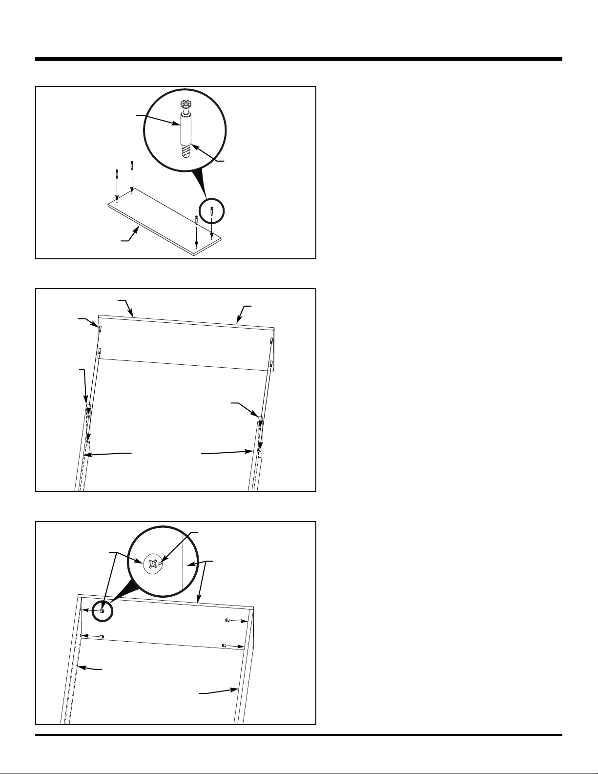
7. Refer to Illustration 7. Install left end panel by
inserting ends of cam bolts, attached to left end
panel, into holes drilled into edges of shelves and
kickplate. Ensure rear edge of left end panel
matches with the unfinished edge of shelves.
8. Refer to Illustration 8. With arrows facing the left
end panel, install cam connectors (from hardware
pack) into holes along upper edge of bottom and
center shelf as shown. Use the Phillips screwdriver
to tighten cam connectors. Turn cam connectors
clockwise to tighten.
Left end
panel
Rear edge
Unfinished
edge
Cam bolt
Left end panel
Arrow
Cam connector
~
Hole
Illustration 9
9. Refer to Illustration 9. With arrow facing the left end
panel, install a cam connector (from hardware
pack) into hole along upper edge of kick plate as
shown. Use the Phillips screwdriver to tighten cam
connector. Turn cam connector clockwise to tighten.
Left end
panel
Arrow
Cam connector
Kickplate
~
Page 4
BOOKCASE
242-6941E
SIDE 4 OF 6 (4/01)
Illustration 10
Cam bolt
Shoulder
Top shelf
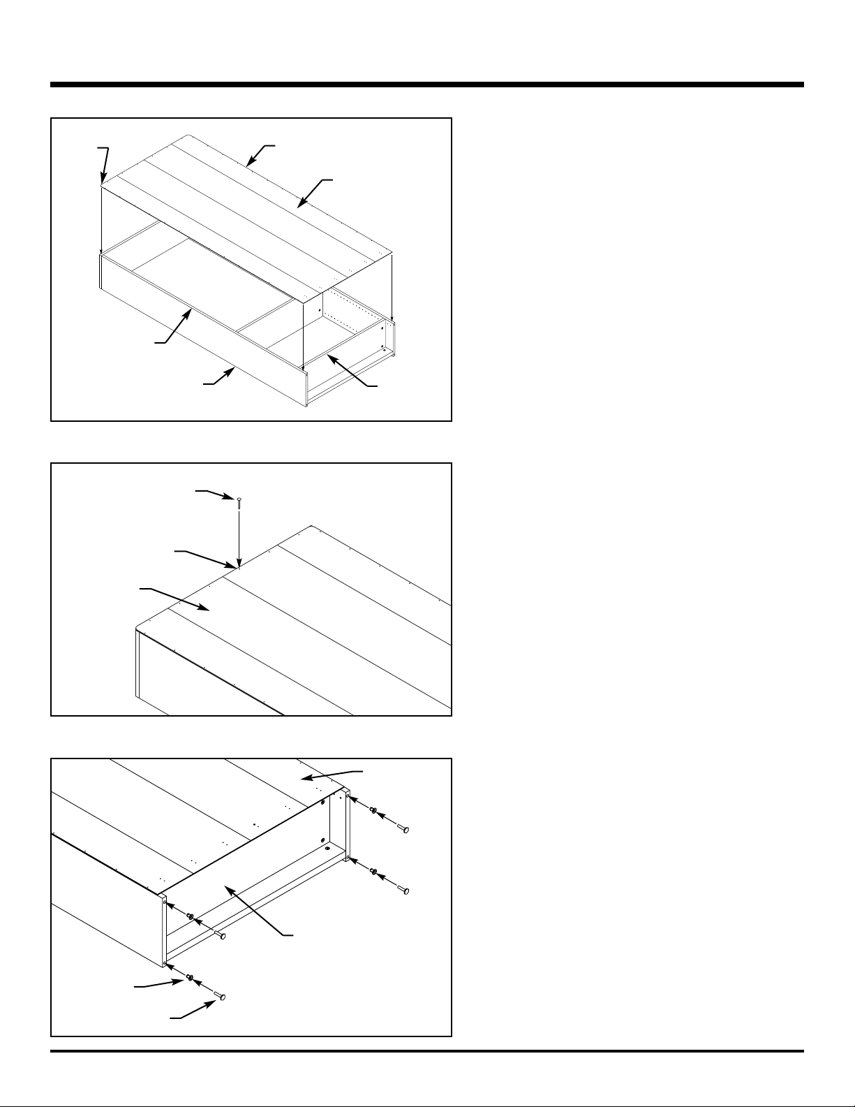
10.Refer to Illustration 10. Lay top shelf, with holes up,
on cardboard or a carpeted surface.
Use the Phillips screwdriver to install cam bolts
(from hardware pack) into top shelf at the locations
shown. Tighten cam bolts until cam bolt shoulder is
flush against surface of top shelf.
Illustration 11
11. Refer to Illustration 11. Install top shelf onto right
and left end panels by inserting cam bolts, installed
in top shelf, into holes along top edge of right and
left end panels. Ensure unfinished edge of top shelf
matches with the unfinished edge of right and left
end panels.
Cam bolt
Unfinished edge
Top of right
end panel
Top shelf
Illustration 12
12.Refer to Illustration 12. With arrows facing the top
shelf, install cam connectors (from hardware pack)
into holes along top edge of right and left end panels. Use the Phillips screwdriver to tighten cam
connectors. Turn cam connectors clockwise to
tighten.
Cam connector
Arrow
Top shelf
~
Unfinished edge
Right end panel
Top of left
end panel
Left end panel
Page 5
BOOKCASE
242-6941E
SIDE 5 OF 6 (4/01)
Illustration 13
13.Refer to Illustration 13. Position bookcase, on card-
board or carpeted surface, with rear and unfinished
edges facing up. Unfold and place back panel onto
bookcase. Ensure unfinished (black) side of back
panel is facing up and radius corners are aligned
with the top corners of bookcase. Align edges of
back panel with edges of bookcase.
Illustration 14
14. Refer to Illustration 14. Locate nail holes along
each edge of back panel. Use the hammer to install
nails (from hardware pack) into each nail hole in
back panel.
Back panel (unfolded)
Bookcase
Rear edge
Unfinished
edge
Unfinished side
(black)
~
Nail
Back panel
Nail hole
~
Radius
corner
Illustration 15
15. Refer to Illustration 15. Locate holes on bottom
edge of left and right end panel. Use the hammer
to install glide inserts (from hardware pack) into
each hole. Thread leveling glides (from hardware
pack) into each glide insert by turning leveling
glides clockwise until leveling glides are flat against
end panels.
After leveling glides are fully installed, use two or
more people to set bookcase upright and position
bookcase where it will be used.
Adjust leveling glides until bookcase is level from
side-to-side and the front of bookcase is
1
/8" higher
than the rear.
Glide insert
Leveling glide
Bottom of
bookcase
Back panel
~
~
Page 6
BOOKCASE
242-6941E
SIDE 6 OF 6 (4/01)
Illustration 16
Illustration 17
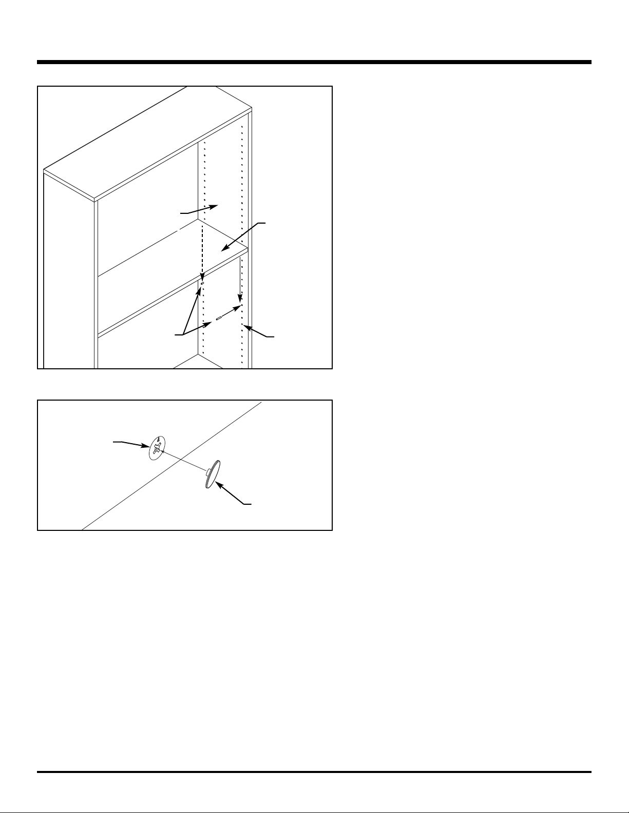
16. Refer to Illustration 16. Locate shelf adjustment
holes in interior walls of bookcase. Install shelf pins
(from hardware pack), at the desired shelf location,
into shelf adjustment holes. Install four pins for
each adjustable shelf and ensure pins are installed
at the same height.
With holes down, position adjustable shelves onto
shelf pins. Ensure shelf pins are seated into holes
in bottom of adjustable shelves.
17. Refer to Illustration 17. Install connector covers
(from hardware pack) onto exposed cam connectors as shown.
Adjustable
shelf
Shelf pin
Adjustment
hole
Interior wall of
bookcase
~
~
Cam connector
Connector cover
 Loading...