

Page 1

key master A2.5 Version Manual www.hominggame.com [email protected]
KEY MASTER
whatsapp:+8618688409495
Manual
(A2.5)
Page 2

key master A2.5 Version Manual www.hominggame.com
Notice: In order to guarantee the safety, please read the
following terms carefully.
1、Presentation…………………………………2
2、Matters need attention……………………2
3、Specification…………………………………2
4、Accessories…………………………………3
5、How to play……………………………3
6、Mother board’s function………………4
7、Account checking………………………5
8、Adjusting and testing……………………6-9
9、Winning probability setting……………9-11
10、SMS function setting-----------------------------11-14
11、Set the alarm system--------15
12、Function statement……15-16
13、rectify the shooting coordinates point…..16
14、Trouble shooting ………17
1
Page 3

key master A2.5 Version Manual www.hominggame.com
and this model is extremly full
of challenges. It is popular with many countries and cities, tooking the fancy of players and producing
so much favourable comment from holders. We advise you to read through out the Instructions so
with the usage of this machine. It is welcome to your coming telegram and
We will solve your problems with sincere
1.Presentation
Congratulations! You exactly bought the gift machine “Key master”,
that you can be familiar
telephone calls if any questions or advices.
management ,which is the faith of our company
2. Matters need attention
Matters need attention in Installation
1) Installing or removing this product, please contact the relevant technical personnel first.
2) The product is applied indoor, avoiding wet places.
3) The product should not be installed in the below places:
Places are wet or leaking
Places with the greenhouse facilities directly affecting.
Places with the floor tilt, uneven or vibration.
4) Be in AC220V, with the wire holed greater than 10A
5) Please don’t place the outlet on the floor otherwise it may lead to an accident.
6) Please don't use the outlet with many pins, it may lead to fire hazard or electric shock.
Use caution:
1) Be sure to turn off the power when verifying and checking up. Please don't use the water to clear up the
machine inside directly, otherwise it may happen to leakage cause by mislead actions, and lead to a fire hazard or
an electric shock.
2) All consumables should be specifications.
3) To prohibit the action of resolving and altering this product, it may cause to a fault. Our company is not
responsible for such cases.
4) In order to improve the quality, it is possible to change the specification without prior notice
3.Specifications
Exterior Appearance…………………………………………D90*W98*H183(cm)
Weight……………………………………………………About 230KG
Power………………………………………………………AC110V
Electric Supply…………………………………………About 150W
Implement…………………………………………………Token
2
Page 4

key master A2.5 Version Manual www.hominggame.com
Coin Box Capacity……………………………………About 5000 coins
4.Accessory
Instruction Book………………………………………… 1 piece
Micro switch ..............………………………………. 4 piece
Wire………………………………………1piece
5.How to play
1)Insert operated coins,strat the game
2)Control the left-right movement of the key by joystick . Press and hold the button to lift the key.
3)Aim at the right slot and release the button ,the key enter into the slot.
4)If the Key manage to go through the slot , The key will twist to unlocks the lock and pull out the gift hanging pin .
5) The gift drop off from pin and falls to the prize basket ..
Spot Hanging gift
3
Page 5

key master A2.5 Version Manual www.hominggame.com
LED1
LED8
6.Illustration of main-board's function
——
(Direction is :From Left To Right)
1、LED 1(Mode 1) (as the pic shown above)------Shows total amount of Inserted coins
2、LED 2(Mode 2) (as the pic shown above):-------Shows total amount of gift payout
3、LED 3(Mode 3) (as the pic shown above) ----Setting the Credit(Signal) Per game
LED 4)Mode 4) (as the pic shown above)-----Setting the Demo music and Playing Music/ Setting the play
game time
4、LED 5(Mode 5)(as the pic shown above)------Setting Each Hook(Hanger) coordinate(Automatically)
5、LED 6(Mode 6) (as the pic shown above)-------“Checking” ,” Testing” ,”Clear”
6、LED 7(Mode 7)(as the pic shown above)-------Setting the probability for each line or for each individual
7、LED 8(Mode 8)(as the pic shown above)-------- SMS function setting
8、Mode 9(the LED1 and LED2 turn on)---------------Set the alarm system
9、MODE Button:----------------------- Use this button to change mode.
10、UP Button -------- In the appointed mode state,Use it to adjust(increase) the number
11、DOWN Button ----- In the appointed mode state,Use it to adjust(Reduce) the number
12、ENTER Button:-------- In the appointed mode state ,Use this button to make a confirmation.
13、CLEAR Button- In the appointed mode state ,Use this button to delete data or return to previous or
4
Page 6

key master A2.5 Version Manual www.hominggame.com
button, said enter mode one when the LED1 light on .Continue to press
will shows the
“Exit”
14、TEST Button—In the appointed mode state,Use this button to test or “shift
7.Account Checking
The way to check account :press “Mode”
“Mode” button, said enter mode two when the LED2 light on .And so on......
Mode 1—Shows Total amount of inserted coins
Mode 2---Shows Total amount of gift payout
Notice:
There are permanent data(Total inserted coins quantity and Total gifts given out quantity) store in the
mainboard, can not through the “clear” way to delete ,except the motherboard broken.
How to check these permanent data ? the way is as follows:
1. Press the “Mode” button to select the “Mode 8” (LED 8 light”) .Shows “8F - - - - ”
2.Press the “Enter” button, appear “8A0000”
3.Use the “UP” and “DOWN” button to imput the permanent data account checking password.The factory Default
setting password is “0003”,press the “enter” button to confirm
4.will shows the LED1 and LED8 are on at the same time, the digital tube will shows the total amounts of insterted
coins quantity,such as the following picture shows “000608”,Means the total amount inserted coins is 608 pcs
5. press the “Test” button, will shows the LED2 AND LED8 are on at the same time, the digital tube
total amount of gifts given out quantity.Such as the following pictures shows “000004”,means the total mount of
gifts given out is 4 pcs.
5
Page 7

key master A2.5 Version Manual www.hominggame.com
Down
6. Press the “Test” button to shift LED1 to LED2 or LED2 to LED1 ,to see the quantity numbers. Press the “Clear”
button to exit.
(About the owner management password setting ,the following will be mentioned. Has the permanent
memory function ,it’s convenience for the owner manage and supervise)
8.Adjusting and Testing
(1)Setting credit of every game : Enter mode 3 to setting.
Method of enter mode 3:press“MODE”,when LED3 light means enter,show“3A - - - X”
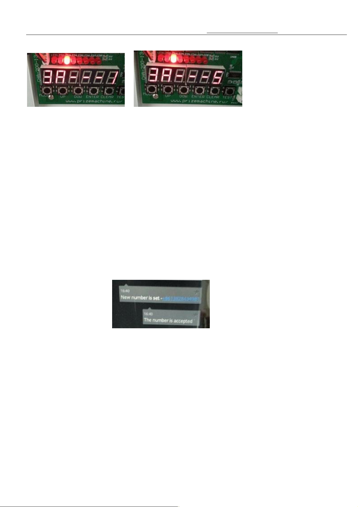
Adjust the credit from 1 pcs(Minimum) to 5 pcs(Maximum) by pressing “Up” or “Down” Button
Will shows “3A - - - 1” To “3A - - -5”,as follows:
1. “ 3A - - -1” = 1 Credit = 1 signal= 1 Game
2. “3A- - - 2” = 2 Credits = 2 signal = 1 Game
3. “3A- - - 3”= 3 Credits = 3 signal = 1 Game
4. “3A- - - 4”= 4 Credits = 4 signal = 1 Game
5. “3A- - - 5”= 5 Credits = 5 signal = 1 Game
(2) Setting the play game time
Press “MODE” button to light up the LED 4, The tube screen shows “4A - - - x” , Press the “ Up” and “
“ button to adjust the game time. The game time range is : from 20 seconds ( Minimum) to 60 Seconds (Maximum)
As the above pictures shows “4A - - 28” means the playing game time is 28 seconds.
(Notice: the suggestion is 25 seconds or 30 seconds)
(3) Setting the Demo music playing time and the method of game music and domo music
Under Mode 4 ,press the “TEST” button ,the tube screen shows “4B - - - x”
you can press “UP” or “DOWN” button to set the music display or not.
“4b- - - 0” means do not display the demo music
6
Page 8

key master A2.5 Version Manual www.hominggame.com
0
“4b- - - 1” means play 1 demo music interval 1 min
“4b - - - 2” means play 1 demo music interval 2 min
“4b - - - 3” means play 1 demo music interval 3 min
“4b- - - 4” means play 1 demo music interval 4 min
“ 4b- - - 5 “ means play play 1 demo music interval 5 min
“4b - - - 6 “ means play demo music all the time
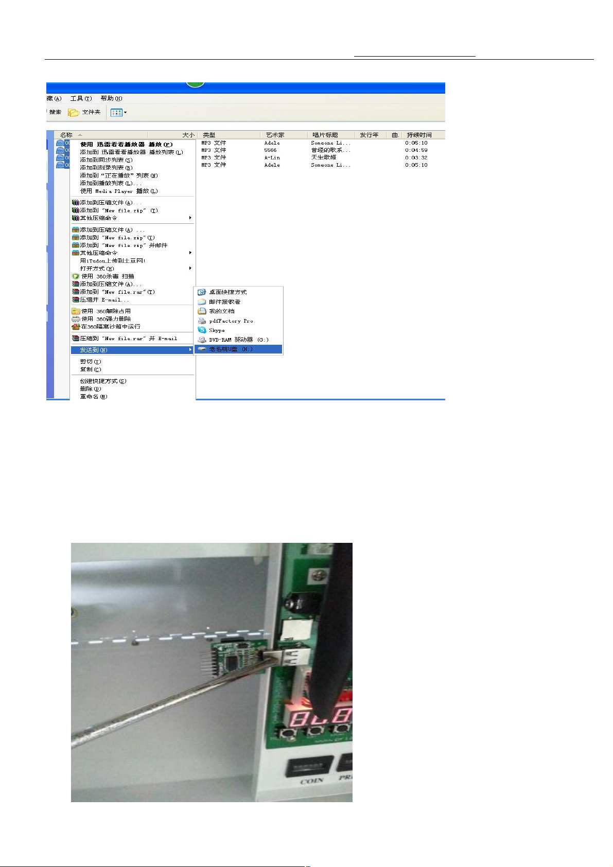
Method of change game music and demo music :
1. Establish a new file in the computer
2. The format of demo music and game playing music require is MP3 format .If 96k frequency can be put into 36
seconds music (the time of total music(Demo+Playing) less than 360 seconds)
3. Choose the music you like, save it into the new file.each music separately named it “0001”, “0002”, “0003”,
“0004” ……and so on,All these music number(name) should be arranged.(“0001” music list No.1, “0002”
music No.2 ……and so on)
4. After finish these arrangement( such as the above picture shows)
5. And then connect the U disk with the Computer, select all the new file music(arranged as per the title), and
send them to the U disk..
7
Page 9
key master A2.5 Version Manual www.hominggame.com
Press "CLEAR" button more than 3
If press "ENTER" button more than 3 second under the setting domo music mode,the digital
6. USB connect:Method of change game music and domo music:
second under the setting domo music mode,the digital shine is ok
7. SD connect:
shine is ok.
8
Page 10

key master A2.5 Version Manual www.hominggame.com
nd the coordinate( Notice:when the key goes
When X
Make sure each row all hook in the same horizontal
,and up ,pass the hole.It will go
can not go through the
Test every switch
rker to test the game
,if Press“CLEAR” more than 10
(Account shows in the mainboard digital
lattice ,after finishing it, press "ENTER"
(Notice:First part is demo music 0001,0002. another part is game music 0003,0004)then choose way。
(4)Setting every prize hook coordinate
Press the MODE button to light up the LED 5。
1、Under the mode 5,Press "ENTER" button, machines will Auto fi
through the lock hole easily in the first step,please adjust the gift hook and then re-setting the coordinate again )
2、When LED shine means have saving this hole coordinate.
3、Notice:Can not power off , during setting the coordinate, or else, can not save coordinate data.。
position is not right ,can use hand to ajust the hook。.(
level)
(5)
Confirm the origin point
Press the MODE button to light up the LED 6。(In the Mode 6 state)
1、Press “ENTER” button under the mode 6, push key will auto move the first hole
on to next hole after finish first one.It will come back after finish 15 hole.(If push key
hole need to come back to mode 5 to calibration.
2、Press “TEST” button under the mode 6,Pushrod will move from left to right and up and push.(
and pushrod.
3、Press “UP” button under the mode 6,will increase10 credit(use for the technical wo
machine)
Press“CLEAR” button will clear the credit which shows on the console
second,will clear the amount credit and amount prize have out.
tube ,in the mode 1 mode 2 shows number will clear )
4、Press“DOWN” more than 10 second,will clear the coins account when LED and digital off.
(Notice:it will affect the prize probability)
9.Setting the Probability
(1)Press the MODE button to light up the LED 7
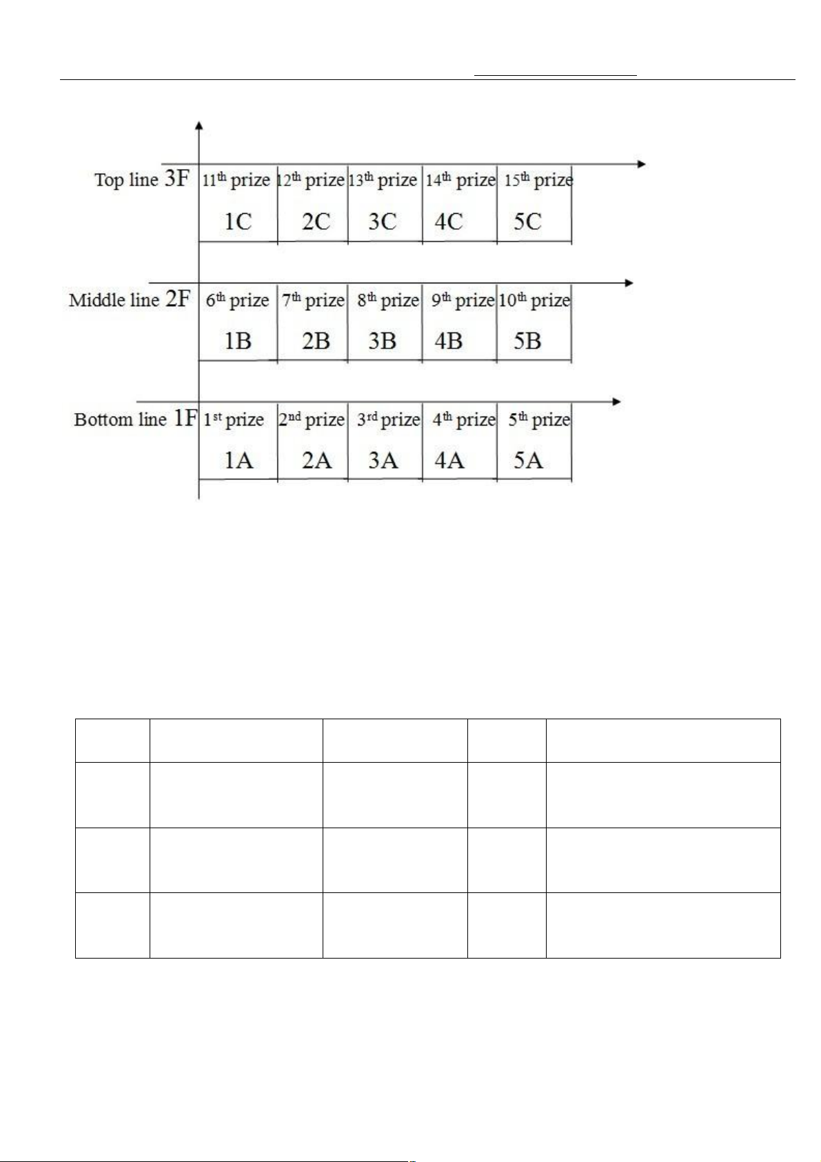
1,Setting every line probability,under mode7, the digital tube display 1F0005,1F means the first line(bottom line)
probability,5 means setting coins(means when insert 5 coins then have change to win the prize on the first line),
press "UP" and "DOWN" button to set the winning probability of this line of
button to set the winning probability of next line of lattice.
9
Page 11
key master A2.5 Version Manual www.hominggame.com
Digital
Tube
1F The winning
probability of the first
2F The winning
probability of the
second line of lattice
3F The winning
probability of the third
Item Setting Range
line of lattice
line of lattice
Default
0-5000 10
0-5000 20
0-5000 30
SET
Explanation
probability=gift value+profit
(coin for the unit)
probability=gift value+profit
(coin for the unit)
probability=gift value+profit
(coin for the unit)
(Notice :In the mode 7,press the “Test” button to shift(change) the setting prize probability for each
line or for each hole(individual) )
10
Page 12
key master A2.5 Version Manual www.hominggame.com
e change to win the prize on the
Setting for each line , each line ,5 holes has the same prize ratio(probability)
Setting for each individual, each hole has its own prize ratio(probability)
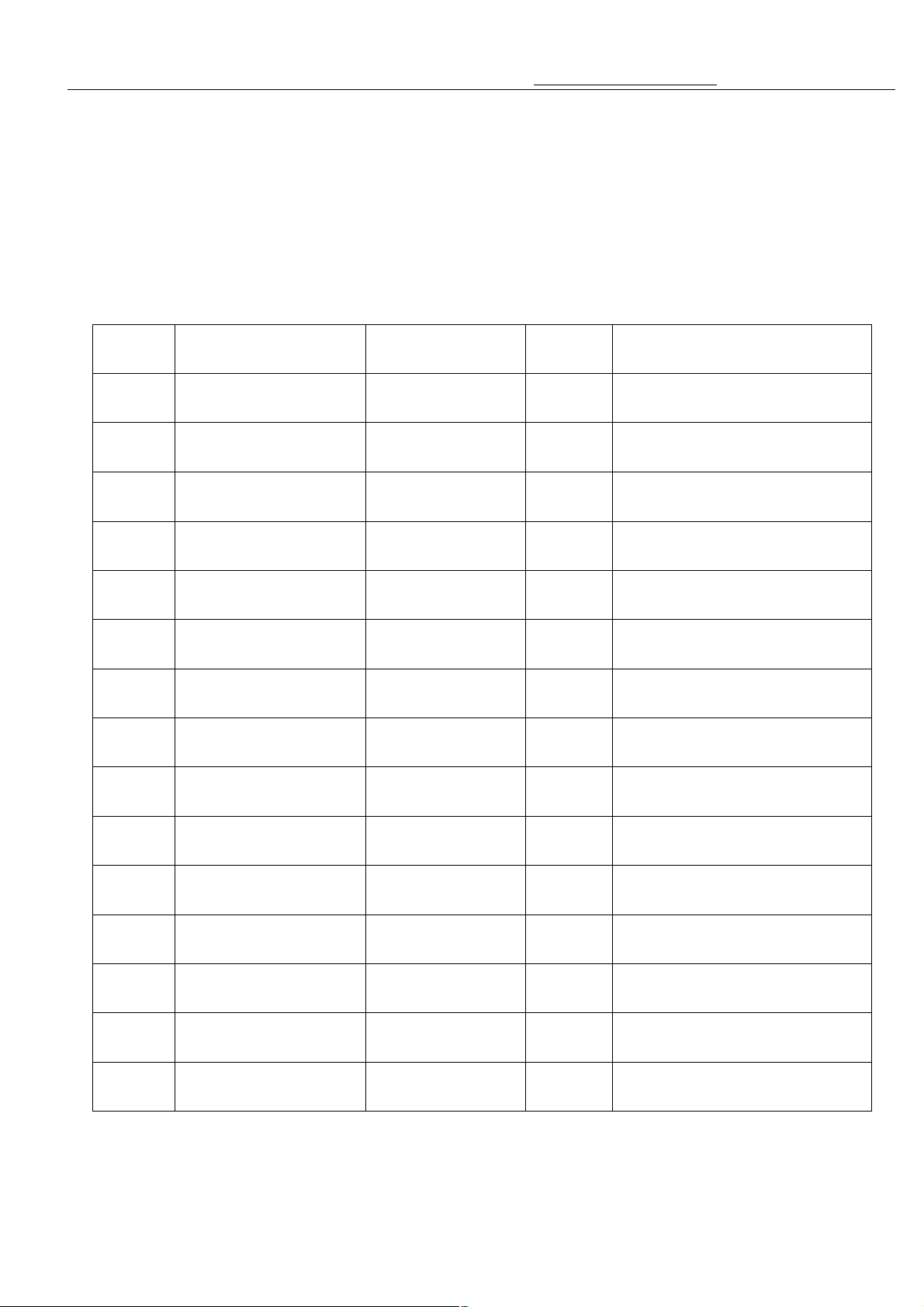
2,Setting every hole probability(Individual), under mode7, the digital tube display 1A0005,1A means the
first hole probability,5 means setting coins(means when insert 5 coins then hav
first line), press "UP" and "DOWN" button to set the winning probability of this hole of lattice ,after finishing it,
press "ENTER" button to set the winning probability of next hole of lattice.
Digital
Tube
1A The 1 hole probability 0-5000 10 probability=gift value+profit
2A The 2 hole probability 0-5000 10 probability=gift value+profit
3A The 3 hole probability 0-5000 10 probability=gift value+profit
4A The 4 hole probability 0-5000 10 probability=gift value+profit
5A The 5 hole probability 0-5000 10 probability=gift value+profit
1B The 6 hole probability 0-5000 20 probability=gift value+profit
2B The 7 hole probability 0-5000 20 probability=gift value+profit
3B The 8 hole probability 0-5000 20 probability=gift value+profit
4B The 9 hole probability 0-5000 20 probability=gift value+profit
5B The 10 hole
probability
1C The 11 hole
probability
2C The 12 hole
probability
3C The 13 hole
probability
4C The 14 hole
probability
5C The 15 hole
probability
Item Setting Range
0-5000 20 probability=gift value+profit
0-5000 30 probability=gift value+profit
0-5000 30 probability=gift value+profit
0-5000 30 probability=gift value+profit
0-5000 30 probability=gift value+profit
0-5000 30 probability=gift value+profit
Default
SET
Explanation
(coin for the unit)
(coin for the unit)
(coin for the unit)
(coin for the unit)
(coin for the unit)
(coin for the unit)
(coin for the unit)
(coin for the unit)
(coin for the unit)
(coin for the unit)
(coin for the unit)
(coin for the unit)
(coin for the unit)
(coin for the unit)
(coin for the unit)
11
Page 13
key master A2.5 Version Manual www.hominggame.com
10.SMS function setting
(1)SET NEW OWNER PASSWORD
Under mode 8 ,press the “ENTER” button ,
the digital tube shows 8AXXXX,,
use“UP” or “DOW” button to enter “0001”,
press “ENTER” button ,
the digital tube shows 1F0000,
then begin to use “UP” or “DOW” button to
input a new owner password to instead of-
the original one “0001” ,
press “ENTER” to confirm the new password .
(2) SET NEW SMS MANAGEMENT PASSWORD
Press “TEST” button to shift to 2F0000,
this is the section of setting SMS management password .
use ‘UP”or “DOW” button to input thenew SMS management password to-
replace the original one “0002”,
press”ENTER” to confirm the new password .
(3) SET NEW ACCOUNT CHECKING PASSWORD .
Press “TEST” to shift to 3F0000,
this is the un removable accountchecking password setting .
Use “UP” or “DOW” button to input the new one to replace the “0003”.
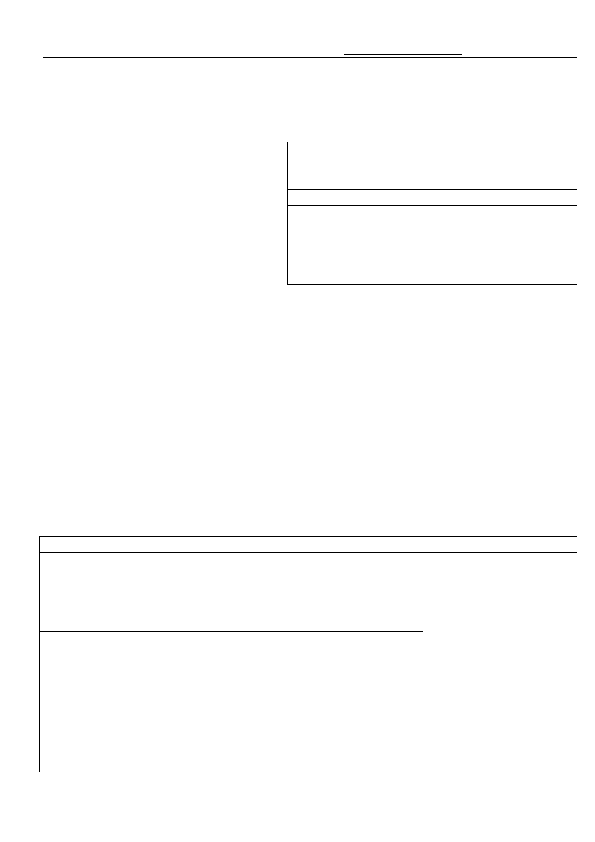
Under Mode8,the SMS Default Management Password is:0002
Digital
tube
shows
1b--XX
2b--XX
3b--XX
4b--XX
Set mobile account checking
password
mobile setting winning
probability password
mobile set the credit for game
Mobile number recognization
password
Function Setting
Range
0000-9999 0000
0000-9999 0011
0000-9999 0022
0000-9999 0033
Display
1F000 New owner password 0-9999
2F000
3F000
New SMS
management
password
New un removable
account checking
Factory Defalut
setting(Password
)
Ref Range
0-9999
0-9999
When finish the password setting
in the mainboard,The owner want
to checking or setting by mobile
phone message .The password
should edit relevant Capital
letter.(A means Number 0, B
means Number 1,……J means
Number 9 )
For example: if want to account
checking , as the default
password is “0000” , so you
Default
Setting
Password
0001
0002
0003
Instructions
12
Page 14
key master A2.5 Version Manual www.hominggame.com
(The default management password
,press “ENTER” , the digital tube shows 1bxxxx, begin to set the accounting checking password ,use “UP’
OW” button to input the new password .“UP” button for the tens digits , “DOWN” button for the single digits.
Press press the “ENTER” button ,the tube twinkles meaning the machine records the password you set .When the
e ,type the password using English letter (A means 0,B means 1,C means
in the
owner use his/her management
and send to the machine .You can get back a
, begin to set the Mobile winning
the new password .“UP” button for the tens digits ,
“DOWN” button for the single digits. Press press the “ENTER” button ,the tube twinkles meaning the machine
the message ,(0
for
o switch in the mobile
only edit the message
“AAAA” and send to the
game machine .If password is
correct, you can receive a
feedback message to you to see
the account
(4) Set mobile account checking password
Under mode 8 (8AXXXX) , input the SMS management password
is :0002)
or “D
owner want to check account via messag
2 ,D means 3 and so on……) , For example : when setting the mobile account checking password is:”0010”
mainboard. So ,the relevant mobile checking password is “AABA”. And then the
mobile phone to edit a message “AABA”(Notice:Need capital),
message showing :
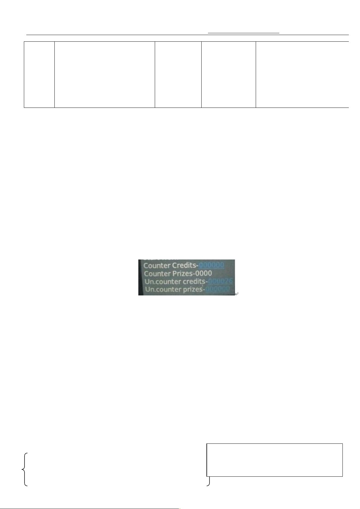
Un-counter-xxxxxxf( unremovable credit-Permanent Data)
Un-prize counter-xxxxxx(un removable prize- Permanent Data )
Counter credits-xxxxxxx(total credit,show on in the motherboard digital tube)
Counter prizes-xxxxxxx( total amount of gift payout, show on in the motherboard digital tube)
(5)mobile setting winning probability password
Under mode 8 (8AXXXX) , input the SMS management password (Default password is :0002),press “ENTER”
button , and then press the “Test” button ,to let the digital tube shows 2bxxxx
probability setting password ,use “UP’ or “DOW” button to input
records the password you set .When the owner want to set the winning probability by mobile, type
should type A ,1 should type B ,2 should type 3………)
(Notice: The message edit format for setting the probability by mobile phone between for each line and
each individual is different).
For example setting winning probability password is “0011” in the mainboard. S
phone message checking password is “AABB”(capital)
AABBA0100,0200,0300,0400,0500 The line 1 hooks setting
This setting for the different line each individual
prize ratio(probability)—need send 3 message to
finish this step
13
Page 15

key master A2.5 Version Manual www.hominggame.com
s for each
, begin to set the Mobile winning probability setting password ,use “UP’
on for the tens digits , “DOWN” button for the single digits.
Press press the “ENTER” button ,the tube twinkles meaning the machine records the password you set .When the
ld type 3………) Sample :
sam
e probability.(One message sending OK)
AABBB0100,0200,0300,0400,0500 The line 2 hooks setting
AABBC0100,0200,0300,0400,0500 The line 3 hooks setting
AABBA means change the bottom line each prize individual prize ratio(Probability)
0100 means the first prize prize ratio is 100;
0200 means the second prize prize ratio is 200;
0300 means the third prize prize ratio is 300;
0400 means the fourth prize prize ratio is 400;
0500 means the fifth hook’s ratio is 500.
AABBB means checking the middle line each prize individual prize ratio
……
AABBC means checking the top line each prize individual prize ratio
……
(Notice :in this situation should need send 3 different messages to the machine to set the 3 different line
prize prize probability individual)
This setting for the each line prize probability of
the 3 line (in the same line,each prize has the
AABB0100,0200,0300
0100 means bottome line the prize (include 5 hooks) ratio is 100;
0200 means middle line (include 5 hooks) ratio is 200;
0300 means top line (include 5 hooks) ratio is 300;
Notice when setting the ratio:
1. the ratio number must 0001≥X≤5000,
2. the ratio number must keep four-digits, and the “0” is necessary.
If setting is successful ,the owner can get back a message “OK” ,otherwise get a “unsuccessful”.
(6)mobile set the credit for game
Under mode 8 (8AXXXX) , input the SMS management password ,press “ENTER” , and then press the “Test”
button , to let the digital tube shows 3bxxxx
or “DOW” button to input the new password .“UP” butt
owner want to set the credit ,text message .(0 should type A ,1 should type B ,2 shou
AACC1.(Notice: this function to change how many credits(signal) per game)
14
Page 16
key master A2.5 Version Manual www.hominggame.com
, begin to set the Mobile winning probability setting password ,use “UP’
or “DOW” button to input the new password .“UP” button for the tens digits , “DOWN” button for the single digits.
ER” button ,the tube twinkles meaning the machine records the password you set . When the
owner text the password (0 should type A ,1 should type B ,2 should type 3………) and sent to the machine ,can get
XXXXXXXXXXXXX) this “XXXXXXXXX” is a
Will shows “3A - - - 1” To “3A - - -5”,as follows:
6. “ 3A - - -1” = 1 Credit = 1 signal= 1 Game
7. “3A- - - 2” = 2 Credits = 2 signal = 1 Game
8. “3A- - - 3”= 3 Credits = 3 signal = 1 Game
9. “3A- - - 4”= 4 Credits = 4 signal = 1 Game
10. “3A- - - 5”= 5 Credits = 5 signal = 1 Game
(7) Mobile number recognization password
Under mode 8 (8AXXXX) , input the SMS management password ,press “ENTER” , and then press the “Test”
button ,to let the digital tube shows 4bxxxx
Press press the “ENT
back a message “The number is accepted” and “New number is setprevious set number .if the password is wrong , owner can get back “Unsuccessful”
11. Set the alarm system
15
Page 17
key master A2.5 Version Manual www.hominggame.com
“UP” or “DOW”
button to adjust ,0 for if machine get shock the owner CAN NOT get a message , 1 for when the machine get shock
Enter Mode 9 ,press “MODE” button ,the LED1 and LED2 turn on ,digital tube shows 9A---x ,use
the owner can get message .
12.Function statement
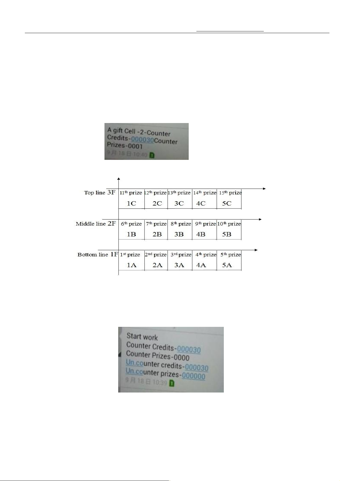
1.Every gift payout the owner can get a message as :A gift cell-xx” the “xx” is the hook code .
Such as the above pictures: A gift Cell- 2 – counter , means the second prize the gift Payout.
2.Everytime the machine turn on ,the owner can get a message as :
Credits-XXXXXX Counter Prizes-XXXX
Un.counter credits-XXXXXX
Un.counter prizes-XXXXXX
16
Page 18
key master A2.5 Version Manual www.hominggame.com
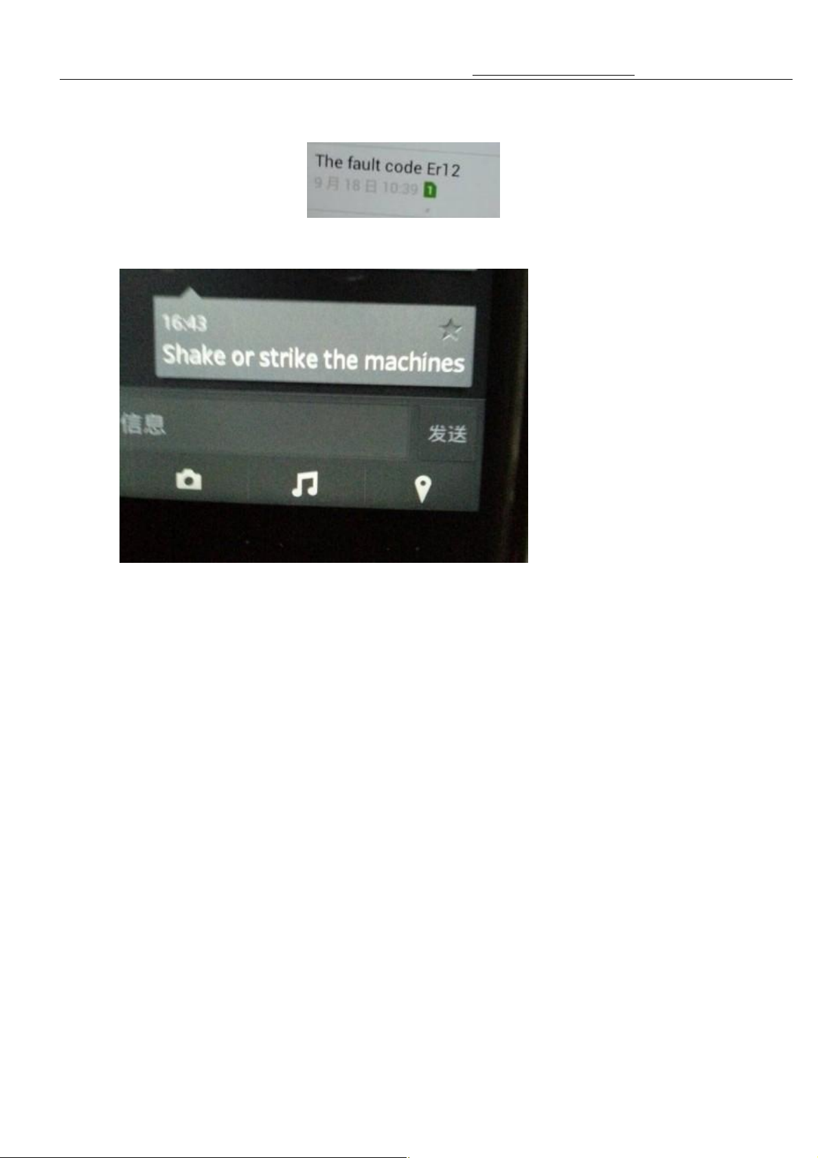
4.If the machine get shock ,the prize door will close at once and the alarm ring ,the owner can get a message
button and turn on the machine at the same time ,don’t loose
NTER” button
3.If machine meet error , the owner can get a message “The fault code Er 01”.
“Shake or strike the machines”. The game will stop .
5.Test the hanging hook ,under mode 5 ,press and don’t release the “TEST” button until the pushrod move .
6.when need to take off hook(s) ,Take away the hook(s), reset the coordinate .
13.rectify the shooting coordinates point
Power off .Press and hold the “ENTER” and “TEST”
the button until the tube shows A 0XX, use “UP” or “DOWN” button adjust the parameter ,press the “E
to save the parameter you set (The tube twinkles).And test the key position is good or not.If good press mode quit
the ajust mode to normal.If not good,continue to ajust. Data setting form 5-20
17
Page 19
key master A2.5 Version Manual www.hominggame.com
ws there is failure of the switch on lower
, pls check
s stuck or not and check the motor and corresponding lines
, pls check the motor
shows there is failure of the switch in the
14、Trouble shooting
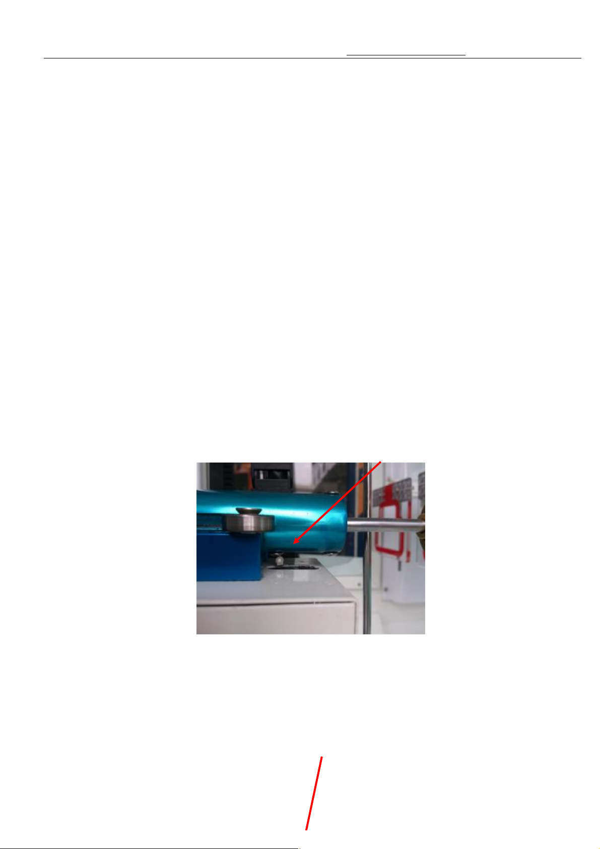
1.When Er01 appears on the digital display, it shows there is failure of the switch on lower front of the pushrod.
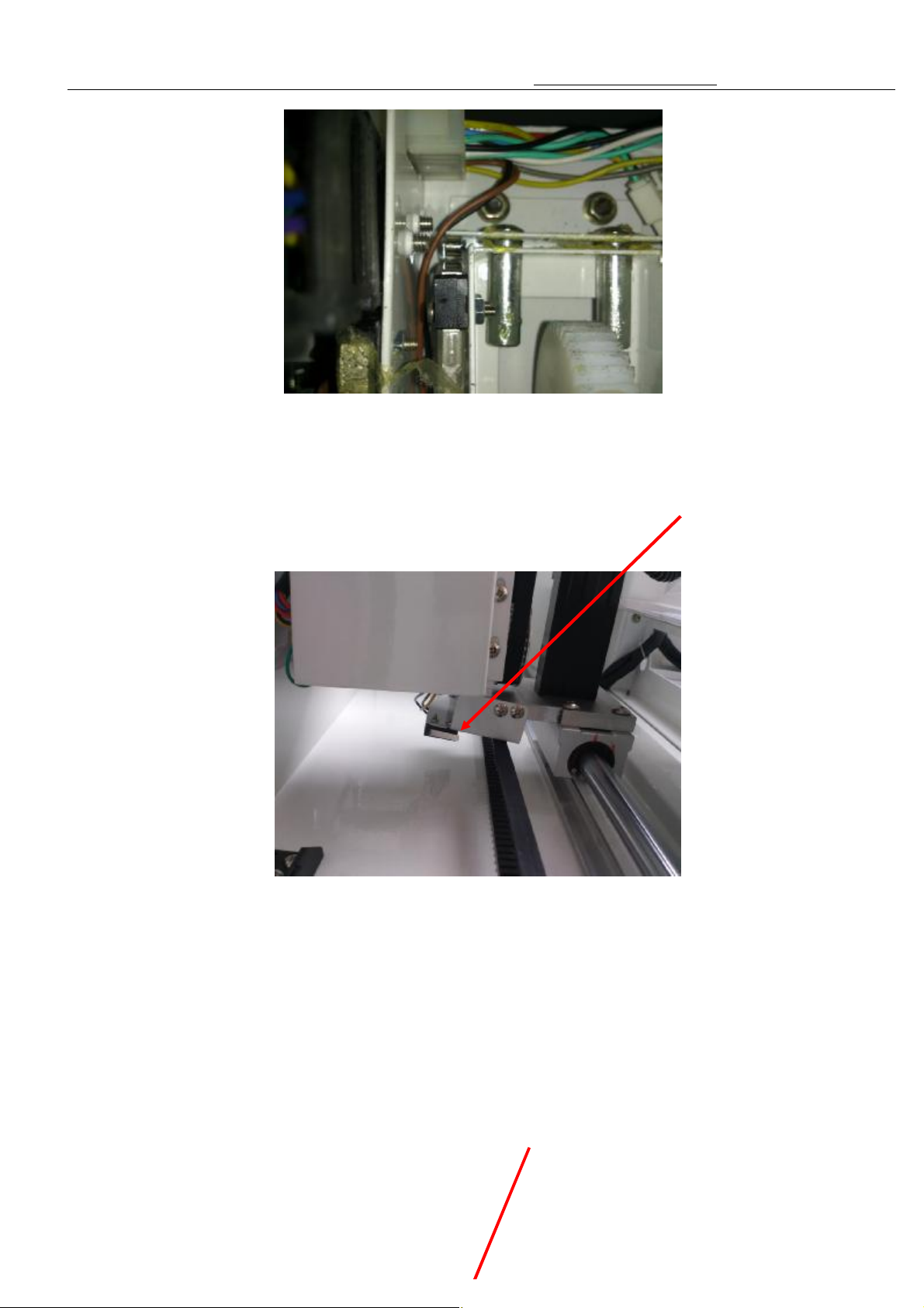
2.When Er02 appears on the digital display, it shows there is failure of the switch in the Moving Box.
3.When Er03 appears on the digital display, it shows there is failure of the switch on right side of the pushrod
mechanism.
4.When Er04 appears on the digital display, it shows there is failure of the switch on low of the Moving Box.
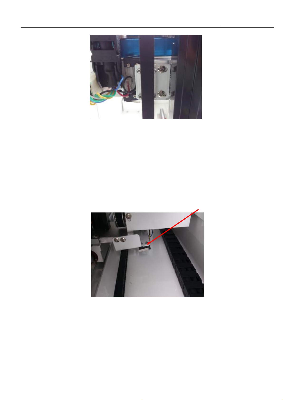
5.When Er05 appears on the digital display, it shows there is failure of the switch on left side of the pushrod
mechanism.
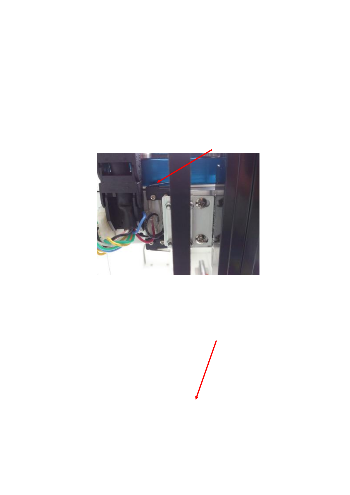
6.When Er06 appears on the digital display, it shows there is failure of the switch on the top of the Moving Box.
7.When Er07 appears on the digital display it shows there is failure of the switch on lower back of the pushrod.
8.When Er08 appears on the digital display it shows there is failure of the first sensor of pushrod.
9..When Er09 appears on the digital display it shows there is failure of the second sensor of pushrod.
10、When Er10 appears on the digital display it shows not connect with accounter .
11, When Er11 appears on the digital display it shows not find the left and right motors sensor
Key master
Fault analysis
1、 When Er01 appears on the digital display, it sho
front of the pushrod. As picture 1
1
Trouble shooting methods:When push rod doesn’t pressure onto the micro switch
whether the push rob i
inside the push rod box. When push rod pressure onto the micro switch
and corresponding lines inside the push rod box.
2. When Er02 appears on the digital display, it
Moving Box. As picture 2
18
Page 20
key master A2.5 Version Manual www.hominggame.com
Check the activities organization go smoothly or not of the
it shows there is failure of the switch on right
t return to the left, the micro switch
t move before the failure. Pls check the drive
t return to the left, the micro switch fail to close and the
and micro switch closed state, pls check the micro
it shows there is failure of the switch on low
2
Trouble shooting methods:
micro position. Then detect the micro switch and corresponding lines.
3. When Er03 appears on the digital display,
side of the pushrod mechanism. As picture 5
5
Trouble shooting methods:When the organization can’
fail to close and the organization doesn’
around the mobile motor and the corresponding lines.
When the organization can’
organization move before the failure,Pls check where does the organization stock on.
When the organization return to the left
switch and corresponding lines.
4. When Er04 appears on the digital display,
of the Moving Box. As picture 4
19
Page 21
key master A2.5 Version Manual www.hominggame.com
When the organization fail to return to the bottom of up and
check the drive move up and down
of up and down and micro switch position in
t return to the right, the micro switch
t move before the failure. Pls check the drive
t return to the right, the micro switch fail to close and the
When the organization return to the right and micro switch closed state, pls check the
When the organization return to the right and micro switch closed state, pls check the
4
Trouble shooting methods:
down and micro switch position not in a closed state, pls
of motor and corresponding lines.
When the organization return to the bottom
a closed state, pls check micro switch and corresponding lines.
5.When Er05 appears on the digital display, it shows there is failure of the switch on right
side of the pushrod mechanism. As picture 3
3
Trouble shooting methods:When the organization can’
fail to close and the organization doesn’
around the mobile motor and the corresponding lines.
When the organization can’
organization move before the failure,Pls check where does the organization stock on.
micro switch and corresponding lines.
20
Page 22
key master A2.5 Version Manual www.hominggame.com
it shows there is failure of the switch on the
t work, pls check
the fluctuation of the moved motor and corresponding lines. When the motor can move up, pls
it shows there is failure of the switch on lower
micro switch and corresponding lines.
6.When Er06 appears on the digital display,
top of the Moving Box. As picture 6
6
Trouble shooting methods: When the fluctuation of the moved motor doesn’
check the micro switch and corresponding lines.
7.When Er07 appears on the digital display
back of the pushrod. As picture 7
21
Page 23
key master A2.5 Version Manual www.hominggame.com
, check
t work before the
7
Trouble shooting methods: (1) When the push rod did not run into micro switch behind
the motor and the corresponding lines inside the box.
(2)When the push rod run into micro switch behind, pls Check the micro switch and the
corresponding lines.
8、When Er08 and Er09 appear on the digital display it shows there is failure of the electric
eye of push rod detected no signal. As picture 8
Trouble shooting methods: When the shaft inside the push rod doesn’
failure, pls detected push rod inside the motor and corresponding lines.
When the push rod inside the shaft turns before failure, detect magic eye plate and the
corresponding lines.
22
8
Page 24
key master A2.5 Version Manual www.hominggame.com
As picture
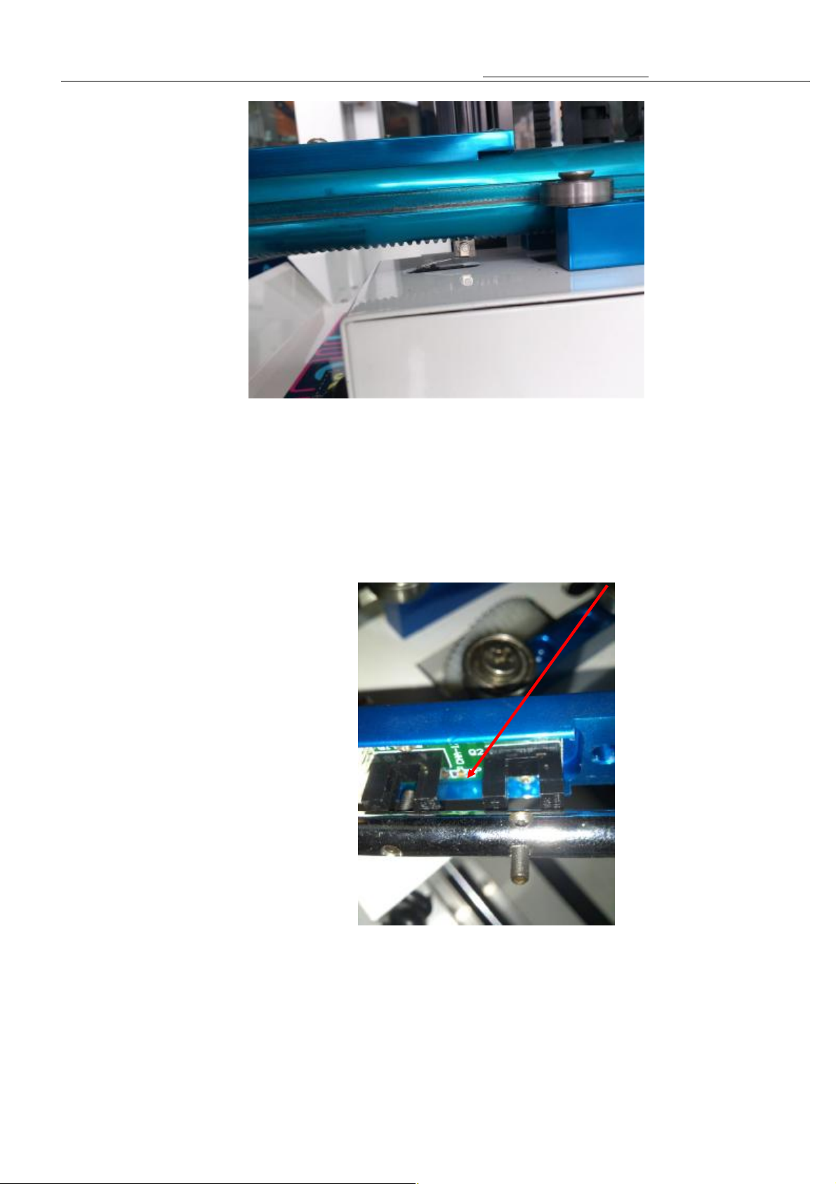
.
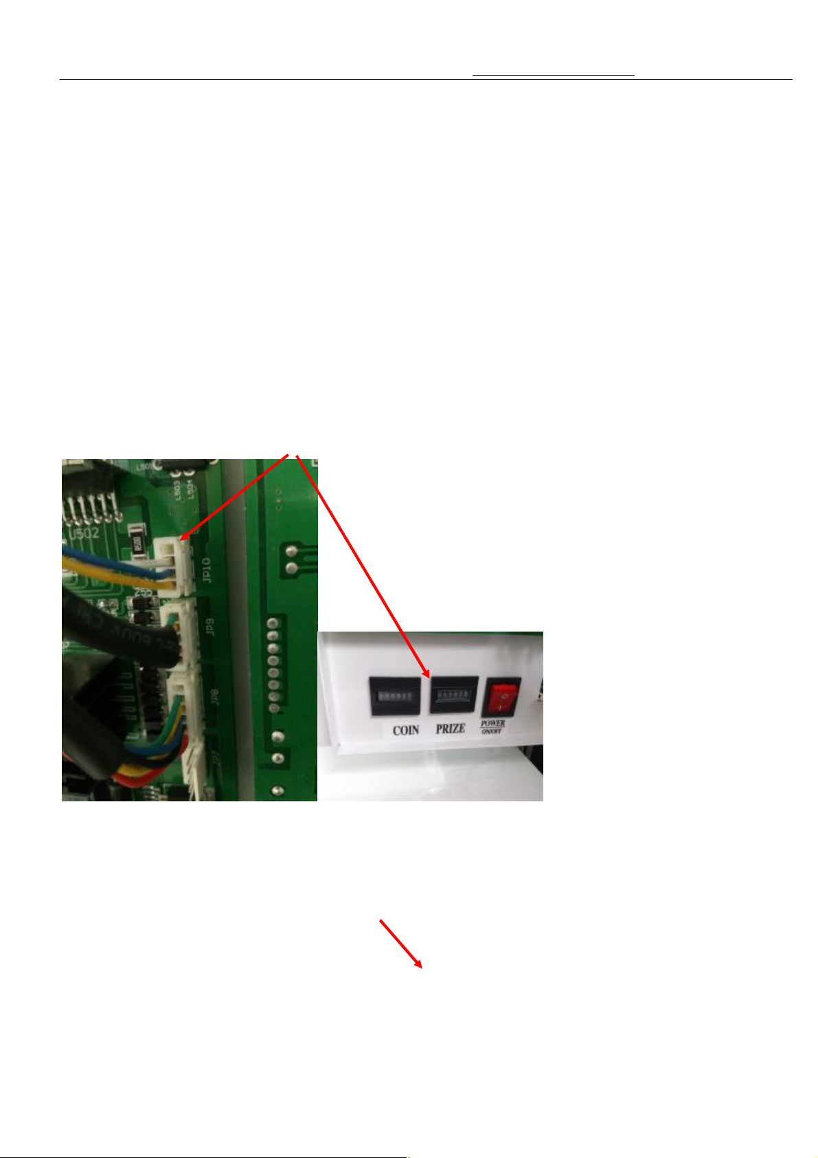
9、 When Er10 appears on the digital display it shows not connect with accounter .
9,10
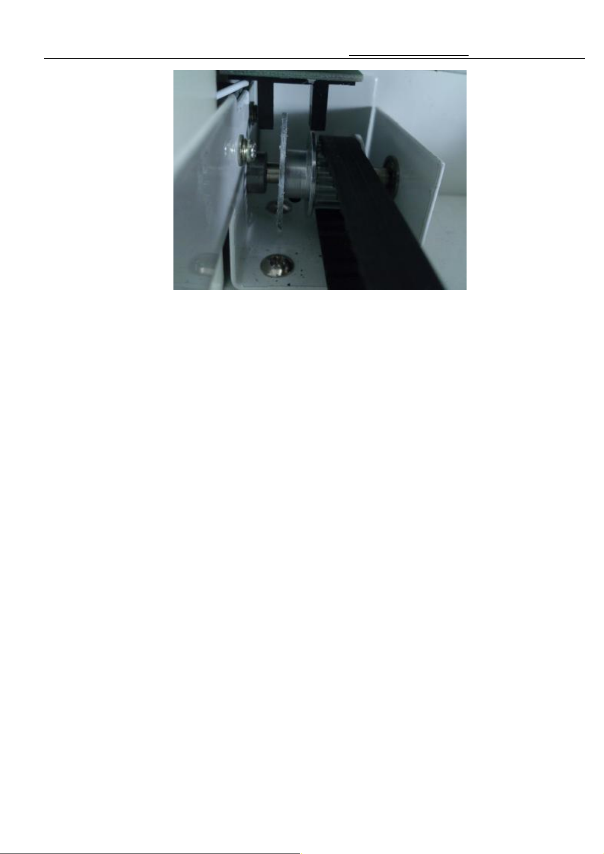
10.When Er11 appears on the digital display it shows not find the left and right motors sensor
As picture 11
23
9 10
Trouble shooting: Inserted the accounter lines or may be the accounter is broken.
Page 25
key master A2.5 Version Manual www.hominggame.com
t move before failure,
the electric
When the fixed electric eye metal sheet can be adjusted and the position is appropriate, pls
11
Trouble shooting: When the left and right of the organization can’
pls check the motor and corresponding lines.
When the left and right of the organization can move before failure, pls check
eye position and baffles position whether appropriate.
check the electric eye baffles and corresponding lines.
24
 Loading...