

Page 1
PRELIMINARY
®
SPECIFICATION SUBMITTAL
MODEL NUMBERS:JOB NAME:
JOB NUMBER:
Page
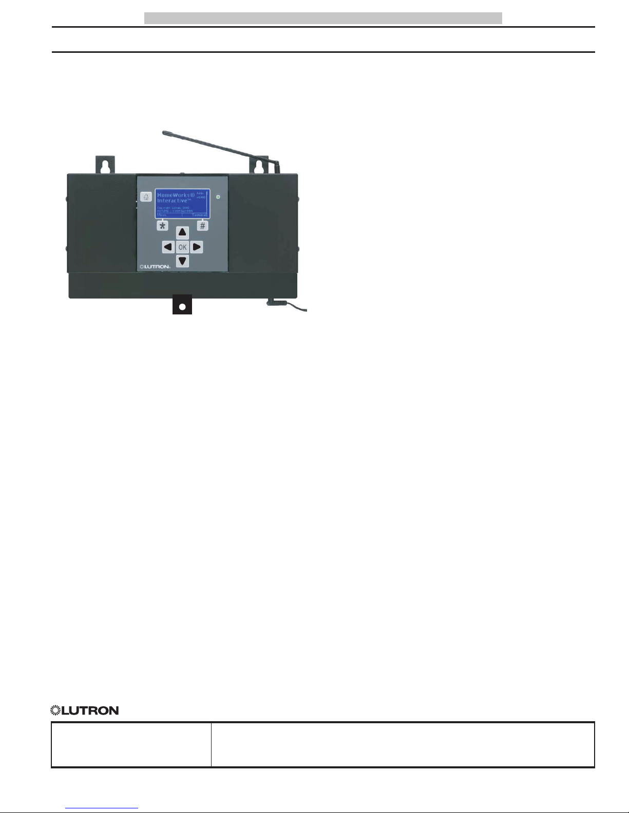
PROCESSORS RF Processor
048-020 1a 11.05.02
HomeWorks InteractiveTM
HomeWorks®RF Processors
RF Processor
DESCRIPTION
HomeWorks RF Processors comprise the major communication hub
of a HomeWorks RF system. Each RF Processor will support up to 32
RF Keypads and up to 64 RF Dimmers. RF system devices communicate with the RF Processor via Radio Frequency.
Up to 4 RF Signal Repeaters may be used with each processor to
extend the range of the RF Processor.
A maximum of 16 RF processors may be connected together in a
system to support a total of 1024 RF dimmers/switches and 512
RF keypads.
MODEL NUMBERS
RF Processors
H-RFP-1P RF Processor with 1 RS232 Port
H-RFP-2P RF Processor with 2 RS232 Ports
Page 2
®
SPECIFICATION SUBMITTAL
MODEL NUMBERS:JOB NAME:
JOB NUMBER:
Page
PROCESSORSHomeWorks InteractiveTM RF Processor
048-020 2a 11.05.02
PRELIMINARY
• Battery backup will maintain programming for up to 10 years under normal
use.
• Built in astronomical time clock.
• Programming is done via RS-232 connection using existing HomeWorks
Interactive software.
• Built in vacation and security modes.
• Advanced keypad button programming
allowing sequences and use of conditional logic for keypad button press events.
• RS-232 port for integrating other equipment such as AV or HVAC.
• Field upgradeable software for the RF
processor allows additional features to
be used in the future.
• Plugs into a standard electrical outlet
using the supplied DC Adapter; no high
voltage wiring necessary.
• Fully compatible with all existing features and operation style of HomeWorks
Interactive.
• Tested to withstand electrostatic discharge without damage or memory loss,
SPECIFICATIONS
Regulatory Approvals
• UL Listed (DC Adapter).
• Complies with the limits for a Class B
digital device, pursuant to Part 15 of the
FCC Rules.
Power
• DC Adapter:
Input power: 120/127VAC,
50/60Hz
Output power: 24VDC, 500mA
• Use only the DC Adapter provided by
Lutron with the RF Processor.
Key Design Features
• Allows installation of HomeWorks
Interactive systems in any home - new or
existing.
• Can be connected to an existing HWI
system or exist as a stand alone radiofrequency (RF) system.
• Graphical LCD with user-friendly menus
for setup and diagnostics.
• Durable membrane keypad for user interface.
in accordance with IEC 6100-4-2.
• Tested to withstand surge voltages without damage or loss of operation,in accordance with IEEE C62.41-1991
Recommended Practice on Surge Voltages
in Low-Voltage AC Power Circuits.
System Communications and Capacity
• Each RF Processor supports up to 64
HomeWorks Maestro RF dimmers/switches
or Tabletop RF Lamp dimmers.
• Each RF Processor supports up to 32
HomeWorks RF Keypads or Tabletop RF
Keypads.
• A maximum of 16 RF processors may be
connected together in a system to support a total of 1024 RF dimmers/switches and 512 RF keypads.
Environment
Ambient operating temperature: 0-40°C,
32-104°F, 0-90% humidity, non-condensing. Indoor use only.
Warranty
• 8 Year Limited Warranty.
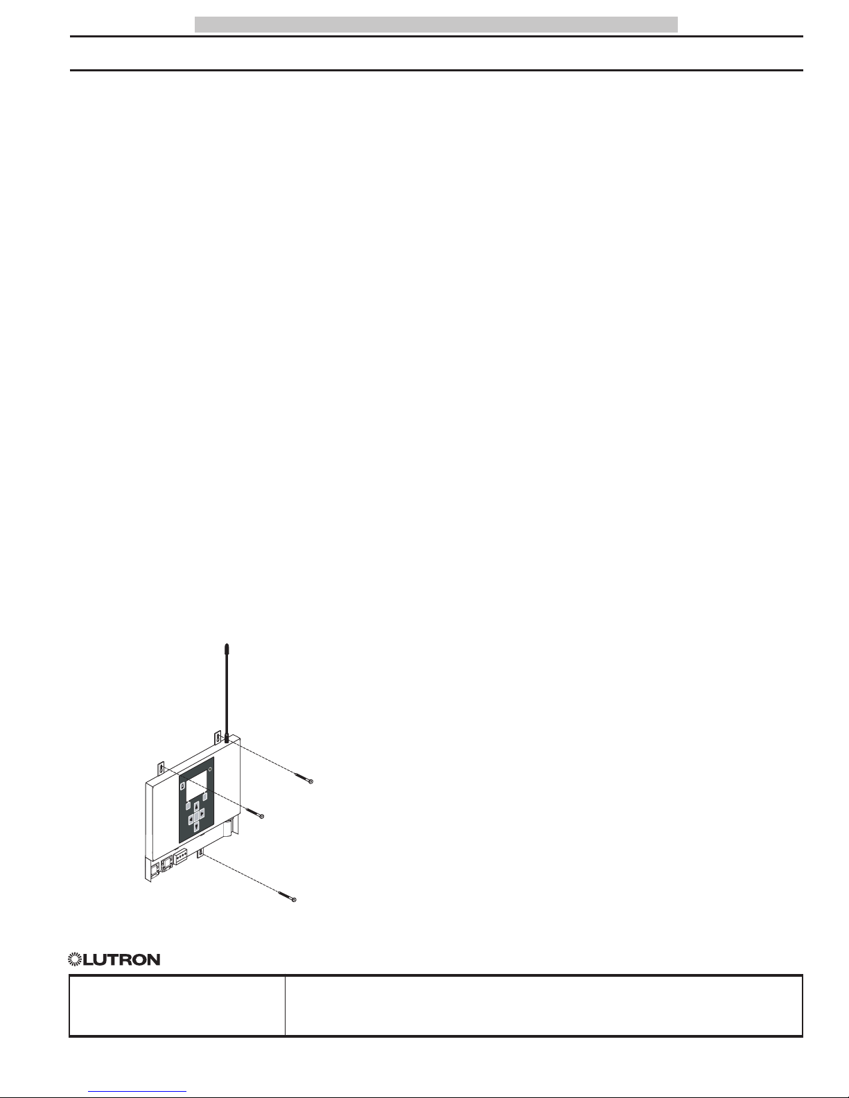
MOUNTING
Mounting Screw
Mounting Screw
Optional Mounting Screw
FCC Information
Note: This equipment has been tested and found to comply
with the limits for a Class B digital device, pursuant to Part 15 of
the FCC rules. These limits are designed to provide reasonable
protection against harmful interference in a residential installation. This equipment generates, uses and can radiate radio frequency energy and, if not installed in accordance with the
instructions, may cause harmful interference to radio communications. However, there is no guarantee that interference will
not occur in a particular installation. If this equipment does
cause harmful interference to radio or television reception,
which can be determined by turning the equipment off and on,
the user is encouraged to try to correct the interference by one
or more of the following measures:
• Reorient or relocate the receiving antenna.
• Increase the seperation between the equipment and
receiver.
• Connect the equipment into an outlet on a circuit different from that to which the receiver is connected.
• Consult the dealer or an experienced radio/TV technician for help.
Caution: Changes or modifications not expressly approved by
Lutron Electronics Co. could void the user’s authority to operate
this equipment.
Industry Canada Information
The term “IC:” before the radio certification number only signifies that Industry Canada technical specifications were met.
#
*
K
O
Page 3
®
SPECIFICATION SUBMITTAL
MODEL NUMBERS:JOB NAME:
JOB NUMBER:
Page
PROCESSORSHomeWorks InteractiveTM RF Processor
048-020 3a 11.05.02
PRELIMINARY
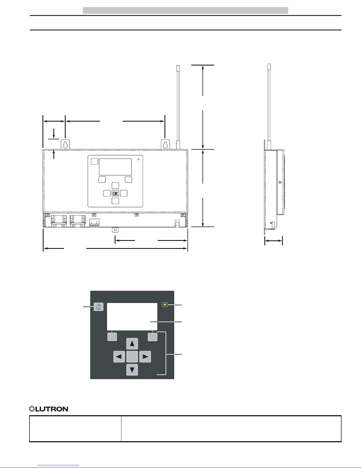
DIMENSIONS
11.54"
(293mm)
8"
(203mm)
1.25"
(32mm)
6.16"
(157mm)
6.7"
(170mm)
0.70"
(18mm)
Front View
(port cover removed)
Side View
TOUCHPAD
Home Key
Returns user to the
Home Screen
Power LED
Menu Navigation Keys
Allows user to navigate
through the various
screens and menus on
the LCD Screen
LCD Screen
5.77"
(147mm)
1.77"
(45mm)
*
OK
#
Page 4
®
SPECIFICATION SUBMITTAL
MODEL NUMBERS:JOB NAME:
JOB NUMBER:
Page
PROCESSORSHomeWorks InteractiveTM RF Processor
048-020 4a 11.05.02
PRELIMINARY
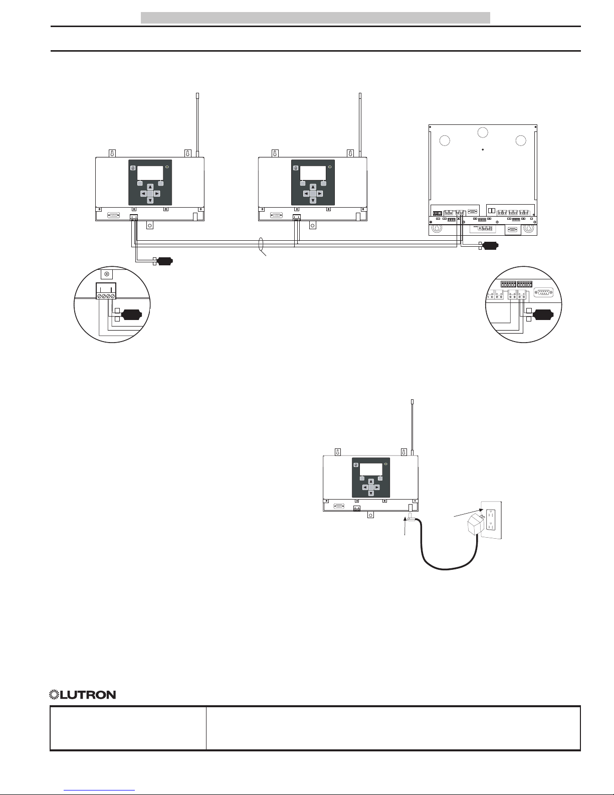
POWER SUPPLY CONNECTION
INTER-PROCESSOR WIRING
WIRING
Processor wiring must be in a daisy-chain
configuration. The total length of wire on
the Inter-Processor Link may be up to
1,000 ft. (305m). For wire runs exceeding
50 ft. (15m) in length, LT-1 Link
Terminators must be used on the processors at both ends of the wire run. Up to 16
Processors (RF or Wired) may be connected
together.
WIRE TYPE
Two pair [one pair #18 AWG (1.0mm
2
),
one pair #22-18 AWG (0.5-1.0mm2) twisted
shielded] Class 2/PELV. Lutron wire, model
# GRX-CBL-346S-500, may be used.
LT-1 Link
Terminator
LT-1 Link
Terminator
Wiring Detail
LT-1 Link
Terminator
LT-1 Link
Terminator
Wiring Detail
RF Processor
RF Processor
Wired
Processor
Pin 1 - 1 No. 18 AWG (1.0mm2)
Pins 3 & 4 - 1 pair No. 22-18 AWG (0.5 - 1.0mm
2
)
twisted/shielded for data
Pin 2 is not connected
#
*
OK
4
3
123
4
4
3
#
*
OK
#
*
OK
123
4
4
123
RXTX
RXTX
RXTX
BUS
BUS
PROCESSOR
1234
2
1
LINK
G1V1 G2 V2 G3V3 G4 V4 G5V5 G6 V6
RXTX
RXTX
BUS
BUS
1234
4
3
4
12 3
4
3
1234123
88
123
1234123
4
4
RXTX
RXTX
PROCESSOR
BUS
BUS
LINK
1234
6
5
Link 7
RS-232 Link
4
4
3
Page 5
®
SPECIFICATION SUBMITTAL
MODEL NUMBERS:JOB NAME:
JOB NUMBER:
Page
PROCESSORSHomeWorks InteractiveTM RF Processor
048-020 5a 11.05.02
PRELIMINARY
SYSTEM COMMUNICATION NOTES
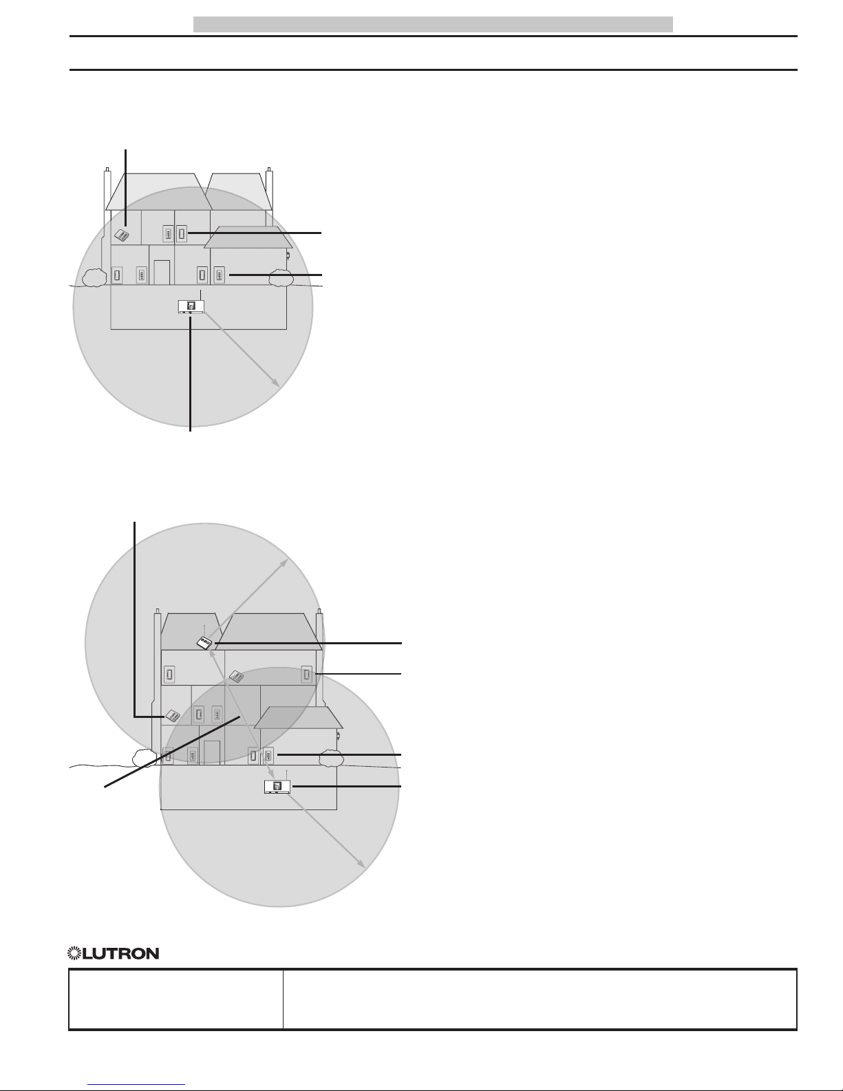
• RF Dimmers and Keypads must be located
within 30 feet (9.14m) of an RF Signal
Repeater or an RF Processor. Multiple
repeaters may be necessary to provide
adequate coverage.
• RF Dimmers cannot be controlled and RF
Keypads will not function until they are
addressed and programmed. See the
HomeWorks Interactive Programming
Utility online help.
• RF Processors and RF Signal Repeaters
provide RF coverage for an area of
approximately 2500 sq. ft. (m
2
). One (1)
RF Processor with four (4) RF Signal
Repeaters will cover an area of approximately 12,500 sq. ft. (m
2
). Additional RF
Processors with associated RF Signal
Repeaters may be added to provide larger
coverage areas.
#
Start
RF Tabletop
Keypad
RF Dimmer
30 Feet (9m) maximum
RF Processor
RF Keypad
Home A: 2500 sq. ft. (232m2) or less - all RF devices within 30' (9m) of RF Processor
#
P/N 292153
RF Tabletop
Keypad
RF Dimmer
30 Feet (9m) maximum
RF Processor
RF Keypad
Home B: 2500 sq. ft. (232m2) or greater - some RF devices more than 30' (9m) from RF Processor
RF Signal Repeater
30 Feet (9m) maximum
60 Feet (18m)
maximum
between RF
Processors and
Repeaters, or
between
Repeaters
*
-
-
 Loading...