

Page 1
product specifications
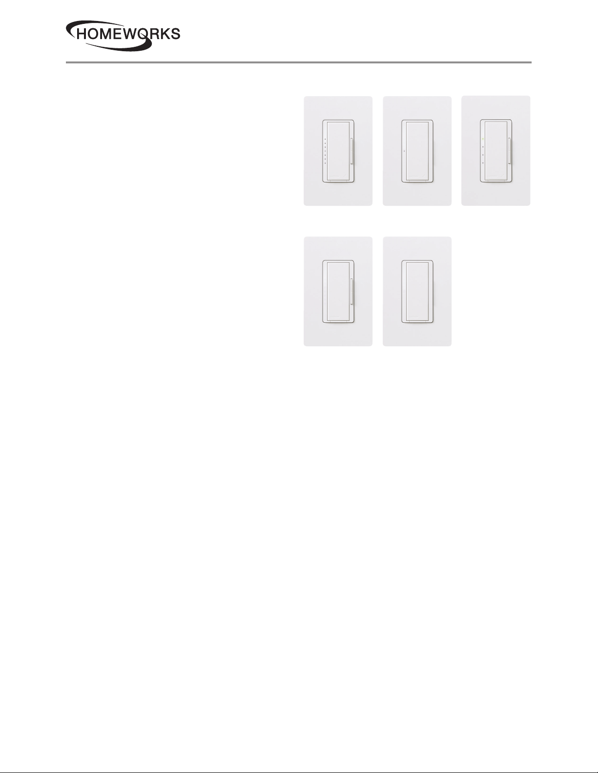
HomeWorks Designer RF Maestro Local Controls
HomeWorks RF Maestro local controls
function much like standard dimmers and
switches, but can be controlled as part of a
lighting control system. Local lighting controls
are useful in locations where single circuits of
lighting need to be dimmed or switched. Local
fan speed controls are useful in locations
where control of a single ceiling paddle fan
is needed.
HomeWorks RF Maestro dimmers incorporate
advanced features such as fade on / fade off,
delayed long fade to off, and rapid full on.
HomeWorks RF Maestro local controls include
a Front Accessible Service Switch (FASS) for
safe lamp replacement. HomeWorks RF
Maestro local controls install in single-pole or
multi-location applications. Remote
dimmers / switches are available for multilocation control.
Use Lutron Designer (Claro or Satin Colors)
wallplates or designer-style wallplates from
other manufacturers. Wallplates are sold
separately. Lutron Claro and Satin Colors
wallplates snap on with no visible means of
attachment. HomeWorks RF Maestro local
controls support color change kits.
Dimmer Switch Fan Speed
Remote Dimmer Remote Switch
02.10.20369305i
Customer Assistance:
1www.lutron.com/support
1.844.LUTRON1 (U.S.A. / Canada)
Page 2

product specifications
02.10.20369305i
HomeWorks Designer RF Maestro Local Controls
Model Numbers
Dimmers
HQRD-6CL-X X 600 W / VA (Incandescent / Halogen / MLV) or 150 W (CFL / LED)
Two-Wire Dimmer*
HQRD-6D-XX 600 W Two-Wire Dimmer
HQRD-6ND-XX 600 W Neutral Wire Dimmer
HQRD-10D-XX 1000 W Two-Wire Dimmer
HQRD-10ND-XX 1000 W Neutral Wire Dimmer
HQRD-6NA-XX 600 W Neutral Phase Adaptive Dimmer
HQRD-F6AN-DV-XX 6 A Fluorescent / LED 3-Wire Dimmer
HQRD-PRO-XX 250 W (CFL / LED) or 500 W / VA Incandescent / Halogen / ELV or 400 VA MLV
Phase Selectable, Neutral Optional dimmer*
Switches
HQRD-8ANS-XX Neutral Wire Electronic Switch
HQRD-8S-DV-XX Two-Wire Electronic Switch
Fan Speed Control (single ceiling paddle fan only [120 V~])
HQRD-2ANF-XX 2 A Fan Speed Control
Remotes (for multi-location installations)
HQD-RD-XX Remote Dimmer (120 V~)
HQD-RS-XX Remote Switch (120 V~)
HQD-RD-277-XX Remote Dimmer (277 V~) (for use with -F6AN-DV only)
HQD-RS-277-XX Remote Switch (277 V~) (for use with -8S-DV only)
Color Change Kits
RK-D-XX Dimmers (-6CL, -6D, -10D, -10ND, -6NA, -PRO, -F6AN-DV)
RK-S-XX Switches (-8ANS and -8S-DV)
RK-AD-XX Remote Dimmer (-RD)
RK-AS-XX Remote Switch (-RS)
RK-F-XX Fan Speed Control (-2ANF)
* Go to www.lutron.com/ledfinder to see all compatible CFL / LED lamps.
Note: “XX” in the model number represents color / finish code. See Colors and Finishes at end of document.
Customer Assistance:
2www.lutron.com/support
1.844.LUTRON1 (U.S.A. / Canada)
Page 3
product specifications
02.10.20369305i
HomeWorks Designer RF Maestro Local Controls
Specifications
Model Numbers Dimmer: HQRD-6CL, HQRD-6D, HQRD-6ND, HQRD-10D, HQRD-10ND, HQRD-6NA,
HQRD-F6AN-DV, HQRD-PRO
Switch: HQRD-8ANS, HQRD-8S-DV
Fan Speed Control: HQRD-2ANF
Remote: HQD-RD, HQD-RS, HQD-RD-277, HQD-RS-277
Color Change Kits: RK-D, RK-S, RK-AD, RK-AS
Power 120 V~ 50 / 60 Hz: -6CL,-6D, -10D, -10ND, -6NA, -2ANF, -8ANS, -RD, -PRO, -RS
120 – 277 V~ 50 / 60 Hz: -F6AN-DV, -8S-DV
Typical Power
Consumption
Regulatory
Approvals
Environment Ambient operating temperature: 32 °F to 104 °F (0 °C to 40 °C), 0% to 90% humidity,
Communications Dimmers and switches communicate with the HomeWorks system through Radio
ESD Protection Tested to withstand electrostatic discharge without damage or memory loss, in
Surge Protection Tested to withstand surge voltages without damage or loss of operation, in accordance
RTISS Equipped Circuitry compensates in real time for incoming line-voltage variations (neutral
Power Failure Power failure memory: should power be interrupted, the control will return to its previous
Mounting Requires a U.S. wallbox. 3 ½ in (89 mm) deep recommended, 2 ¼ in (57 mm)
Wiring Use only remote dimmers (-RD / -RD-277) and remote switches (-RS / -RS-277) with
Warranty www.lutron.com/TechnicalDocumentLibrary/warranty.pdf
Dimmer / Switch / Fan Speed Control: 0.6 W
Test conditions: load is off and nightlight mode is enabled.
Remote Dimmer / Switch: 0 W
Test conditions: load is off.
UL, CSA (all except -6CL, -6NA and -PRO), cUL (-6CL, -6NA, -PRO only), NOM, FCC, IC,
COFETEL, ANATEL (all except -6NA, -6CL and remotes)
non-condensing. Indoor use only.
Frequency (RF) and must be located within 30 ft (9 m) of a repeater. Remote
dimmers / switches are not required to be within a specific range of a repeater.
accordance with IEC 61000-4-2.
with IEEE C62.41-1991 Recommended Practice on Surge Voltages in Low-Voltage AC
Power Circuits.
connection required). -PRO only.
state when power is restored.
deep minimum.
dimmers / switches / fan speed controls. Up to 9 -RD / -RD-277 or -RS / -RS-277 may be
used with controls.
Customer Assistance:
3www.lutron.com/support
1.844.LUTRON1 (U.S.A. / Canada)
Page 4

product specifications
HomeWorks Designer RF Maestro Local Controls
Design Features
Dimmer
• On a single-tap, lights fade ON or OFF.
• On a double-tap, lights go to full ON.
• When ON, press and hold the tapswitch to
engage the delayed long fade to OFF.
• Light levels can be fine-tuned by pressing and
holding the dimming rocker until the desired
light level is reached.
• Neutral and two-wire dimmers available.
Switch
• On a single-tap, lights or motors turn ON
o r O F F.
• Neutral and two-wire switches available.
Fan Speed Control
• On a single-tap, fan turns ON or OFF.
• Fan speeds can be selected by pressing and
holding the fan speed control rocker until the
desired fan speed is reached.
• Controls one paddle-type ceiling fan
(Permanent split-capacitor motor) up to 2 A.
Not for use with shaded-pole type motors
(e.g., bath exhaust fans).
• Provides 4 quiet speeds plus OFF.
• Not for use with fans that have integrated fan
speed and / or light control modules.
• Requires a neutral connection.
02.10.20369305i
Customer Assistance:
4www.lutron.com/support
1.844.LUTRON1 (U.S.A. / Canada)
Page 5
product specifications
HomeWorks Designer RF Maestro Local Controls
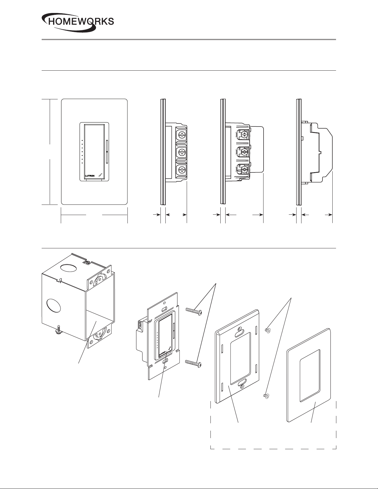
Dimensions
All dimensions are shown as: in (mm)
02.10.20369305i
4 11⁄16
(119 )
Front View
2 15⁄16
(75)
5/16
Side View
(8)
Mounting and Parts Identification
1 1⁄8
(30)
5/16
(8)
Side View
-2ANF only
1 11⁄16
(43)
5/16
(8)
Side View
-RD-277 and
-RS-277 only
1 3⁄8
(35)
Wallbox
Control Mounting Screws
Adapter Mounting Screws
Control
Wallplate Adapter Wallplate
Wallplate Ada pter / Wallplate
purchased separately
Customer Assistance:
5www.lutron.com/support
1.844.LUTRON1 (U.S.A. / Canada)
Page 6
product specifications
02.10.20369305i
HomeWorks Designer RF Maestro Local Controls
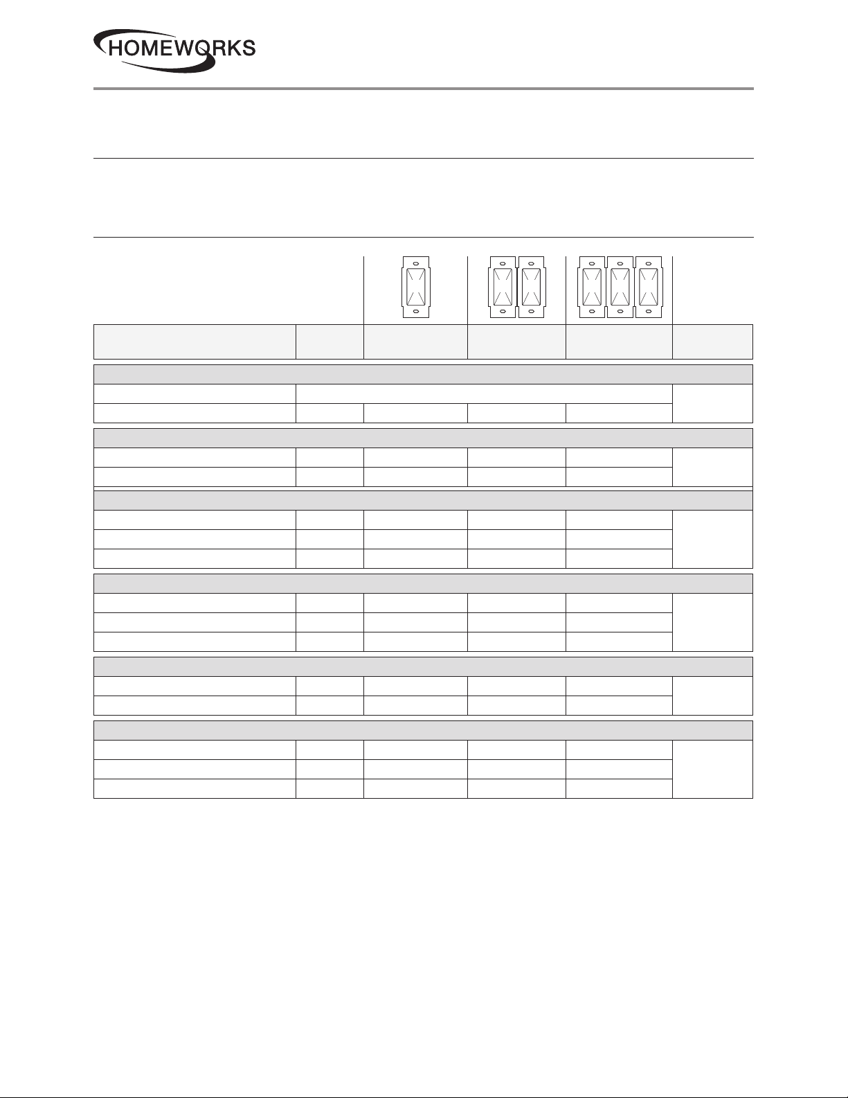
Ganging and Derating
When combining controls in the same wallbox, derating is required (see Load Type and Capacity).
No derating is required for remote dimmers, remote switches, or fan speed controls.
Load Type and Capacity
A B B B C B
Load Type
HQRD-6CL
1
Minimum
Load
Incandescent/Halogen/CFL/LED see Mixing Lamp Types, page 9
2,3
MLV
HQRD-6D
1
50 W/ VA 450 W/600 VA 400 W/500 VA 300 W/400 VA
Incandescent/Halogen 50 W 600 W 500 W 400 W
2
MLV
HQRD-6NA
1,4
LED Varies
2,3
MLV
HQRD-6ND
1,4
LED Varies
50 W/ VA 450 W/600 VA 400 W/500 VA 300 W/400 VA
5
150 W 150 W 150 W
2
5 W 600 W 500 W 400 W
5 W/ VA 450 W/600 VA 400 W/500 VA 300 W/400 VA
5
150 W 150 W 150 W
A
Not GangedBEnd of GangCMiddle of Gang
Neutral
Connection
No
No
YesIncandescent/Halogen/ELV
YesIncandescent/Halogen 10 W 600 W 500 W 400 W
2,3
MLV
HQRD-10D
1
Incandescent/Halogen 50 W 1000 W 800 W 650 W
2
MLV
HQRD-10ND
1,4
LED Varies
10 W/ VA 450 W/600 VA 400 W/500 VA 300 W/400 VA
50 W/ VA 800 W/1000 VA 600 W/800 VA 500 W/650 VA
5
150 W 150 W 150 W
No
YesIncandescent/Halogen 10 W 1000 W 800 W 650 W
2,3
MLV
1
Dimmer Load Type:
• -6D, -6ND,-10D, -10ND: designed for use with permanently-installed incandescent, LED, magnetic low-voltage, or tungsten
halogen only.
• -6CL: designed for use with permanently-installed incandescent, magnetic low-voltage, tungsten halogen, CFL, or LED only.
• -6NA: designed for use with permanently-installed incandescent, LED, electronic low-voltage, magnetic low-voltage, or tungsten
halogen only.
Note: Do not install dimmers to control receptacles or motor-operated appliances.
2
Low-Voltage Applications: -6CL, -6D, -6ND, -10D -10ND: use with magnetic (core and coil) low-voltage transformers only. Not for use with
electronic (solid-state) low-voltage transformers.
Low-Voltage Applications: -6NA: use with electronic (solid-state) or magnetic (core and coil) transformers.
Operation of a low-voltage circuit with lamps inoperative or removed may result in transformer overheating and premature failure. Lutron
strongly recommends the following:
• Do not operate low-voltage circuits without operative lamps in place.
• Replace burned-out lamps as soon as possible.
• Use transformers that incorporate thermal protection or fused transformer primary windings to prevent transformer failure due
to overcurrent.
3
Do not mix CFL or LED loads with MLV loads.
4
Power Boosters / Load Interfaces: -6NA, -6ND and -10ND can be used to control power boosters / load interfaces. For a list of compatible
power boosters / load interfaces see Compatible Power Boosters and Load Interfaces, page 10.
5
Minimum load depends on lamp and is not limited to a particular wattage. Refer to the LED Product Selection Tool at
www.lutron.com/ledtool
10 W/ VA 800 W/1000 VA 600 W/800 VA 500 W/650 VA
Customer Assistance:
6www.lutron.com/support
1.844.LUTRON1 (U.S.A. / Canada)
Page 7
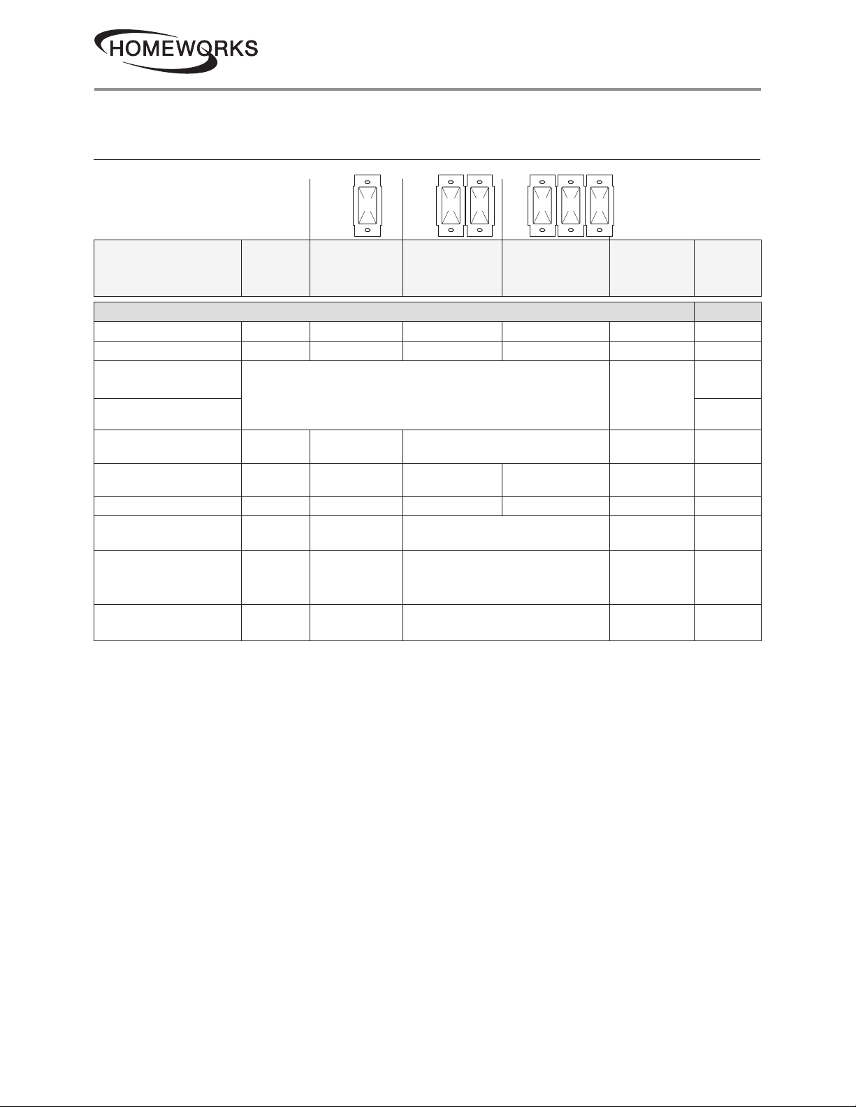
product specifications
HomeWorks Designer RF Maestro Local Controls
Load Type and Capacity (continued)
A B B B C B
02.10.20369305i
Required
Phase
Mode
Load Type
Minimum
Load
A
Not GangedBEnd of GangCMiddle of Gang
Neutral
Connection
HQRD-PRO
LED 1 bulb 2250 W 200 W 150 W Optional
CFL 1 bulb 2250 W 200 W 150 W Optional
MLV Transformer
with LEDs
ELV Transformer
See Application Note #559 (P/N 048559) at www.lutron.com
No Derating Required
Required
with LEDs
MLV Transformer
with Halogen
ELV Transformer
with Halogen
Incandescent / Halogen 5 W
Dimmable Fluorescent
Ballast
Hi-lume 1% 2-wire (LTE)
LED Driver
PHPM-PA / 3F and
GRX-TVI
1
Neutral is recommended for best dimming performance, if available, but is not required for this load type.
2
Minimum load shown is for neutral connected operation. If no neutral is used, minimum load is
2 bulbs LED/CFL, or 25 W Incandescent / Halogen.
3
Power Boosters / Load Interfaces: -HQRD-PRO can be used to control power boosters / load interfaces. For a list of compatible power
boosters / load interfaces see Compatible Power Boosters and Load Interfaces, page 10.
Note: For dimming MLV fixtures, the maximum lamp wattage is typically 70%–85% of the transformer’s VA rating. For actual transformer
efficiency, contact the manufacturer. The total VA rating of the transformer(s) shall not exceed the VA rating of the dimmer.
3
10 W
10 W 500 W 400 W 300 W Required Reverse
2
1 ballast
1 driver
1 interface 3 interfaces No Derating Required Required Forward
400 VA
(300 W)
No Derating Required Required Forward
500 W 400 W 300 W Optional
3.3 A
(400 VA)
No Derating Required Required Forward
3.3 A (400 W)
20 drivers
No Derating Required Required Forward
max.
1
1
1
Either
Forward
Forward
Reverse
Either
Customer Assistance:
7www.lutron.com/support
1.844.LUTRON1 (U.S.A. / Canada)
Page 8
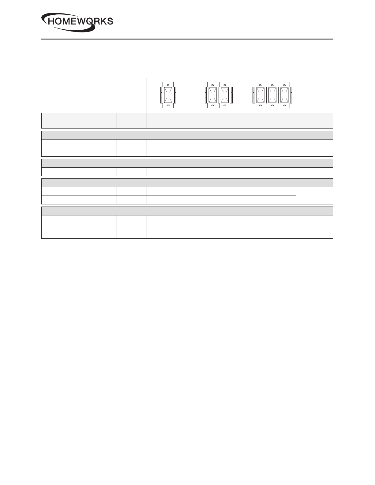
product specifications
HomeWorks Designer RF Maestro Local Controls
Load Type and Capacity (continued)
Do not remove outside fins on ends of ganged controls (shaded areas below).
02.10.20369305i
-8ANS, -8S-DV, -RD-277, and -RS-277
have fins that need to be removed for
A B B B C B
multigang installations.
Load Type
HQRD-F6AN-DV
1,2,3
Fluorescent/LED Drivers
HQRD-2ANF
4
Minimum
Load
0.05 A 6 A 5 A 3.5 A
1 ballast 60 ballasts 50 ballasts 35 ballasts
A
Not Ganged
B
End of Gang
C
Middle of Gang
Neutral
Connection
Yes
Ceiling Fan 0.083 A 2 A 2 A 2 A Yes
HQRD-8ANS
Lighting 10 W 8 A 6.5 A 5 A
Motor 0.08 A 1/4 HP 5.8 A 1/4 HP 5.8 A 1/6 HP 4.4 A
HQRD-8S-DV
Lighting 40 W/ VA 8 A
1,5
5,6
8 A (2-gang);
7 A (3-gang)
7 A
Yes
No
Motor 0.4 A 1/10 HP 3 A
Note: Do not install dimmers to control receptacles or motor-operated appliances.
1
Power Boosters / Load Interfaces: -F6AN-DV and -8ANS can be used to control power boosters / load interfaces. For a list of compatible
power boosters / load interfaces see Compatible Power Boosters and Load Interfaces, page 10.
2
Fluorescent Dimmer Load Type: -F6AN-DV: designed for use with permanently installed 3-wire 120 V~ or 277 V~ line voltage control
fluorescent ballasts or LED drivers. Use with only Hi-lume, Hi-lume 3D, Hi-Lume Compact SE, Eco-10, or EcoSystem (H3D-, FDB-, ECO-,
HL3-, EC5-, L3D). Do NOT use with any other ballasts or drivers. Do not install to control receptacles or motor-operated appliances.
3
Maximum Load: The maximum load for the -F6AN-DV is either the derated load or the number of ballasts, whichever is LESS.
4
Ceiling Fan Application: -2ANF
• Use to control one paddle-type ceiling fan (permanent split-capacitor).
• Use the ceiling fan’s pull chain to set its speed to the highest setting.
• Do not use to control fans that use shaded-pole motors (e.g., bath exhaust fans).
• Do not use to control fans that have integrated fan speed controls (e.g., fans that have a remote control), unless the integrated control is
removed from the ceiling fan.
• Do not connect to any other motor-operated appliance or to any lighting load type.
• Do not use to control a fan lighting load (e.g., light kit).
5
Switch Load Type:
• -8ANS and -8S-DV: designed for use with permanently installed 120 V~ incandescent, magnetic low-voltage, electronic low-voltage,
tungsten halogen, fluorescent, CFL, LED, or motor loads.
• -8S-DV can also be used with permanently installed 277 V~ magnetic low-voltage or fluorescent loads.
6
Shunt Capacitor: Some -8S-DV installations may require the use of a shunt capacitor; this is especially necessary for load types sensitive
to leakage current (e.g., fluorescent ballasts). If load flickers, install a shunt capacitor. Optional shunt capacitor must be installed inside the
load fixture or in a separate J-box. For shunt capacitor installation see Wiring Diagram 4, 9, or 10.
Customer Assistance:
8www.lutron.com/support
1.844.LUTRON1 (U.S.A. / Canada)
Page 9
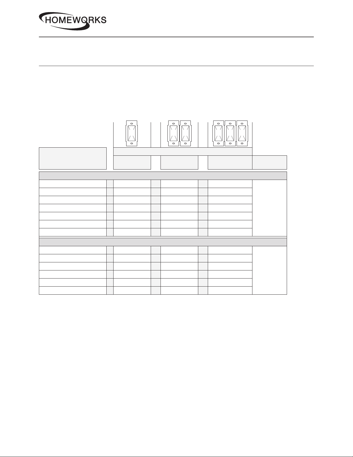
product specifications
02.10.20369305i
HomeWorks Designer RF Maestro Local Controls
Mixing Lamp Types
Mixing lamp types (using a combination of CFL / LED, and Incandescent / Halogen bulbs) and
ganging with other dimmers or electronic switches may reduce maximum wattage as shown in the
chart below.
Example: If you have two dimmers ganged together and you have two 24 W bulbs installed (total
CFL Wattage = 48 W), on one dimmer, you may add up to 300 W of incandescent or halogen
lighting to that one dimmer. Repeat the exercise for the other dimmer with which it is ganged.
A B B B C B
Total Incandescent / Halogen Wattage
Total CFL/LED Wattage
HQRD-6CL
1,2
0 W + 50 W – 600 W Or 50 W – 500 W Or 50 W – 400 W No
1 W – 25 W + 0 W – 500 W Or 0 W – 400 W Or 0 W – 300 W
26 W – 50 W + 0 W – 400 W Or 0 W – 300 W Or 0 W – 200 W
51 W – 75 W + 0 W – 300 W Or 0 W – 200 W Or 0 W – 100 W
76 W – 100 W + 0 W – 200 W Or 0 W – 100 W Or 0 W – 50 W
101 W – 125 W + 0 W – 100 W Or 0 W – 50 W Or 0 W
126 W – 150 W + 0 W Or 0 W Or 0 W
HQRD-PRO
3
0 W + 5 W3 – 500 W Or 5 W3 – 400 W Or 5 W3 – 300 W Optional
1 W – 50 W + 0 W – 400 W Or 0 W – 300 W Or 0 W – 200 W
51 W – 100 W + 0 W – 300 W Or 0 W – 200 W Or 0 W – 100 W
101 W – 150 W + 0 W – 200 W Or 0 W – 100 W Or 0 W
151 W – 200 W + 0 W – 100 W Or 0 W Or 0 W
201 W – 250 W + 0 W Or 0 W Or 0 W
1
Dimmer Load Type -6CL is designed for use with permanently-installed incandescent, CFL, LED, magnetic low-voltage, or tungsten
halogen only. Do not install dimmers to control receptacles or motor-operated appliances.
2
Do not mix CFL and LED loads with MLV loads.
3
Minimum load shown is for neutral connected operation. If no neutral is used, minimum load is 2 bulbs CFL / LED, or 25 W
Incandescent / Halogen.
A
Not Ganged
B
End of Gang
C
Middle of Gang
Neutral
Connection
Customer Assistance:
9www.lutron.com/support
1.844.LUTRON1 (U.S.A. / Canada)
Page 10
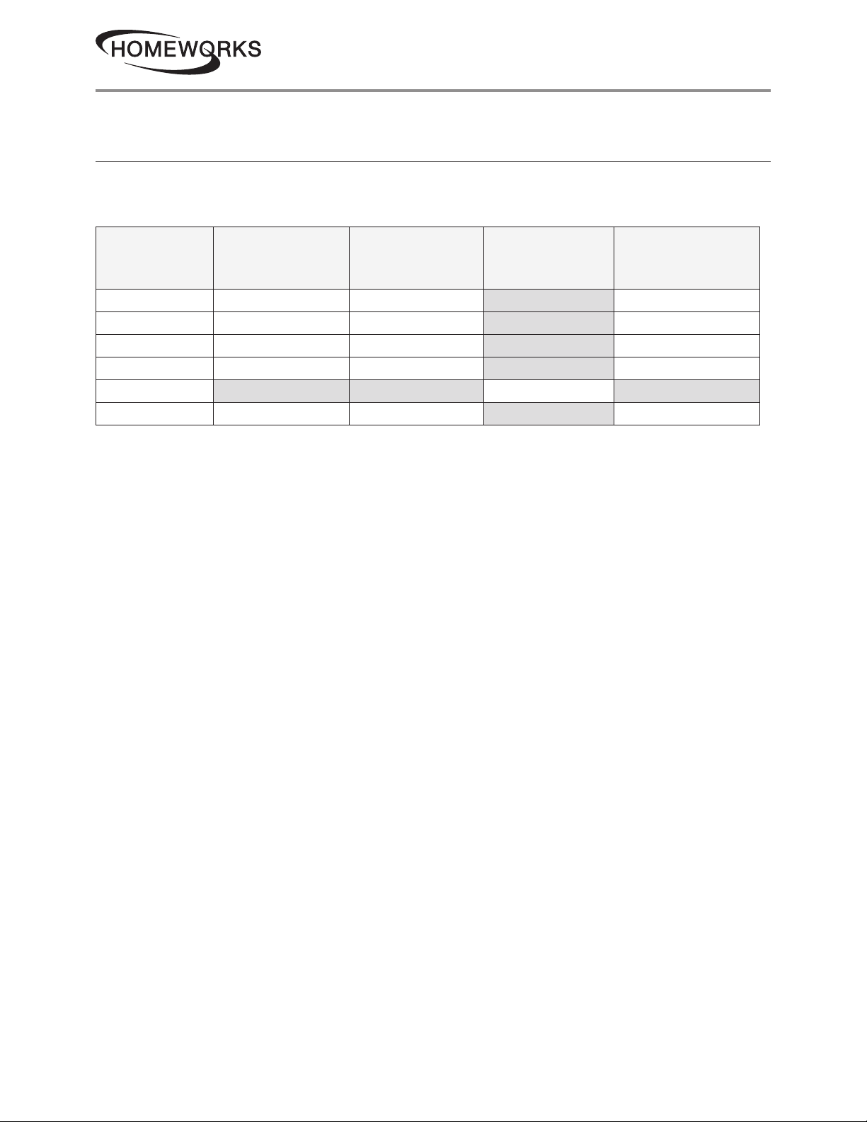
product specifications
02.10.20369305i
HomeWorks Designer RF Maestro Local Controls
Compatible Power Boosters and Load Interfaces
Some local controls can be used to control power boosters or load interfaces. Up to three power
boosters or load interfaces can be used with one control. See table below for a list of controls and
compatible power boosters and load interfaces.
Phase Adaptive
Control
HQRD-6ND
HQRD-10ND
HQRD-6NA
HQRD-F6AN-DV
HQRD-8ANS
HQRD-PRO
1
Only the GRX-TVI is compatible with the HQRD-F6AN-DV at 277 V~. All other power modules are 120 V~ only.
Power Modules:
PHPM-PA-120-WH;
PHPM-PA-DV-WH
1
3-wire Fluorescent
Power Modules:
PHPM-3F-120-WH;
PHPM-3F-DV-WH
Switched Power
Module:
PHPM-SW-DV-WH
0 – 10 V- Interface
and Switching
Module: GRX-TVI
Customer Assistance:
10www.lutron.com/support
1.844.LUTRON1 (U.S.A. / Canada)
Page 11
product specifications
OFF ON
HomeWorks Designer RF Maestro Local Controls
Operation
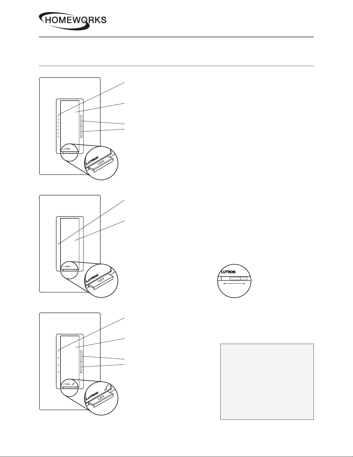
Dimmer
Status LEDs
(not on Remote Dimmers)
Indicate light level; glow softly as night light when light is off
Tapswitch
Tap on / off
Dimming Rocker
Press to brighten
Press to dim
FASS
Front Accessible Service Switch
Switch
02.10.20369305i
Fan Speed Control
Status LED
(not on Remote Switches)
Indicates load status; glows softly as night light when light is off
Tapswitch
Tap on / off
FASS
Front Accessible Service Switch
Status LEDs
Indicate speed level; glow softly as night light when fan is off
Tapswitch
Tap on / off
Speed Control Rocker
Press to increase speed
Press to decrease speed
Or RD-277 and
RS-277 only
OFF ON
Important Notice
FASS: Front Accessible
Service Switch
To replace bulb, remove power
FASS
Front Accessible Service Switch
by pulling the FASS out fully on
all controlling devices.
After replacing bulb(s), push the
FASS back in fully to restore
power to the control(s).
Customer Assistance:
11www.lutron.com/support
1.844.LUTRON1 (U.S.A. / Canada)
Page 12
product specifications
HomeWorks Designer RF Maestro Local Controls
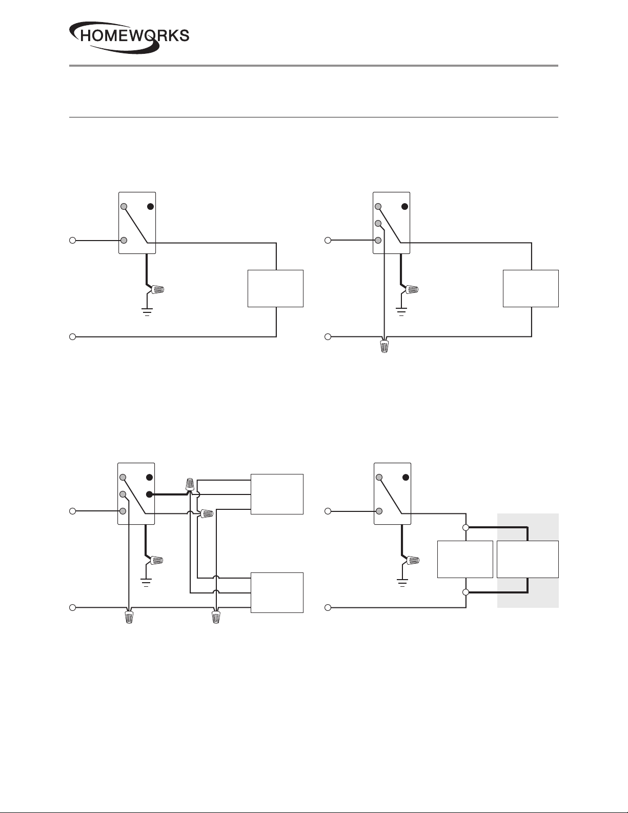
Wiring Diagrams
02.10.20369305i
Wiring Diagram 1
Single-Location Installation without Neutral
1
-6CL, -6D, -10D, -PRO
Dimmer
Brass
Black
Line / Hot
120 V~
50 / 60 Hz
Ground
Neutral
Blue
Green
1
Load
Wiring Diagram 3
Single-Location Fluorescent Dimmer Installation
-F6AN-DV with Lutron Ballast / LED Driver
Wiring Diagram 2
Single-Location Installation with Neutral
-6ND, -10ND, -6NA, -2ANF, -8ANS, -PRO
Dimmer / Sw itch / Fan Speed Control
Brass
Silver
Black
Line / Hot
120 V~
50 / 60 Hz
Ground
Neutral
Blue
Green
1
Wiring Diagram 4
1
Single-Location 2-Wire Switch Installation
-8S-DV with Optional Shunt Capacitor
1
Load
1
2
Dimmer
Brass
Silver
Black
Line / Hot
120 –277 V~
50 / 60 Hz
Ground
Neutral
Note: Bolded lines in diagrams indicate leads on products.
1
When using controls in single-location installations, tighten the blue terminal. Do not connect the blue terminal to any other wiring or
to ground.
2
Optional Shunt Capacitor must be installed inside the load fixture or in a separate J-box.
Blue
Orange
Green
1
Black
Orange
White
Black
Orange
White
Lutron
Ballast / LED
Driver
Lutron
Ballast / LED
Driver
Brass
Black
Line / Hot
120 –277 V~
50 / 60 Hz
Neutral
Switch
Ground
Blue
Green
1
Optional
Load
Shunt
Capacitor
2
Continued on next page...
Customer Assistance:
12www.lutron.com/support
1.844.LUTRON1 (U.S.A. / Canada)
Page 13
product specifications
HomeWorks Designer RF Maestro Local Controls
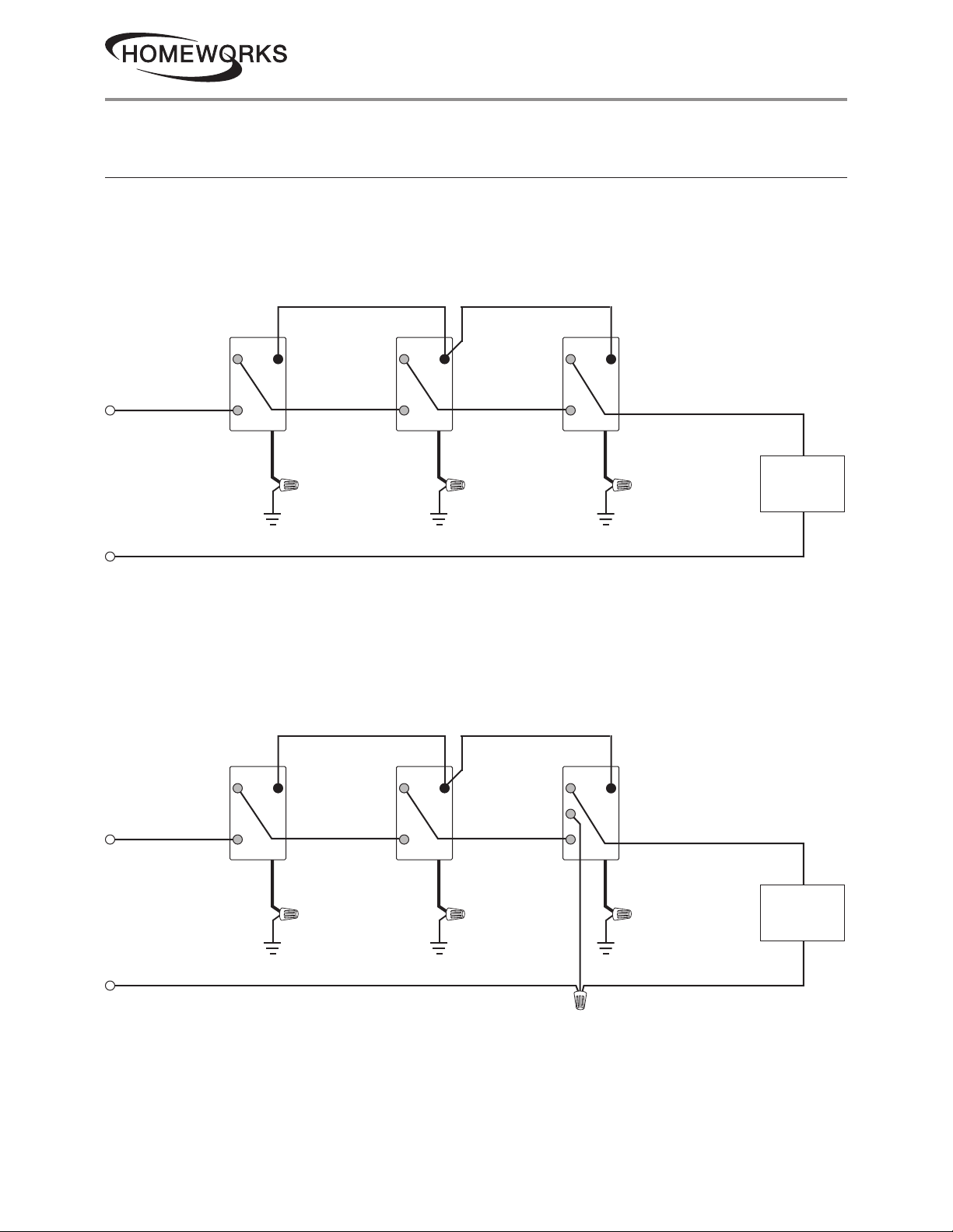
Wiring Diagrams (continued)
Wiring Diagram 5
Multi-Location Installation without Neutral
-6CL, -6D, -10D, and -PRO with HQD-RD
1
02.10.20369305i
Remote Dimmer
or Dimmer
Line / Hot
120 V~
50 / 60 Hz
Neutral
Remote Dimmer
or Dimmer
Dimmer or
Remote Dimmer
BrassBrassBrass
BlackBlackBlack
GroundGroundGround
BlueBlueBlue
GreenGreenGreen
Wiring Diagram 6
Multi-Location Installation with Neutral
1,2
-6ND, -10ND, -6NA, -2ANF and -PRO with HQD-RD; -8ANS with HQD-RS
Remote Dimmer
or Remote Switch
Remote Dimmer
or Remote Switch
Dimmer / Sw itch /
Fan Speed Control
Note: Dimmer can be
installed in any location
in the circuit.
Load
2
BrassBrass
Line / Hot
120 V~
50 / 60 Hz
Neutral
Note: Bolded lines in diagrams indicate leads on products.
1
Up to 9 Remote Dimmers/Remote Switches may be connected to the Dimmer / Switch / Fan Speed Controls. Total blue terminal wire length
may be up to 250 ft (76 m), except -PRO which is up to 150 ft (45 m).
2
Neutral-Wire Dimmers / Switches / Fan Speed Controls must be connected on the Load side of a multi-location installation, except the
-PRO which can be connected in any position.
Brass
Silver
BlackBlackBlack
BlueBlueBlue
GreenGreenGreen
Load
GroundGroundGround
Continued on next page...
Customer Assistance:
13www.lutron.com/support
1.844.LUTRON1 (U.S.A. / Canada)
Page 14
product specifications
HomeWorks Designer RF Maestro Local Controls
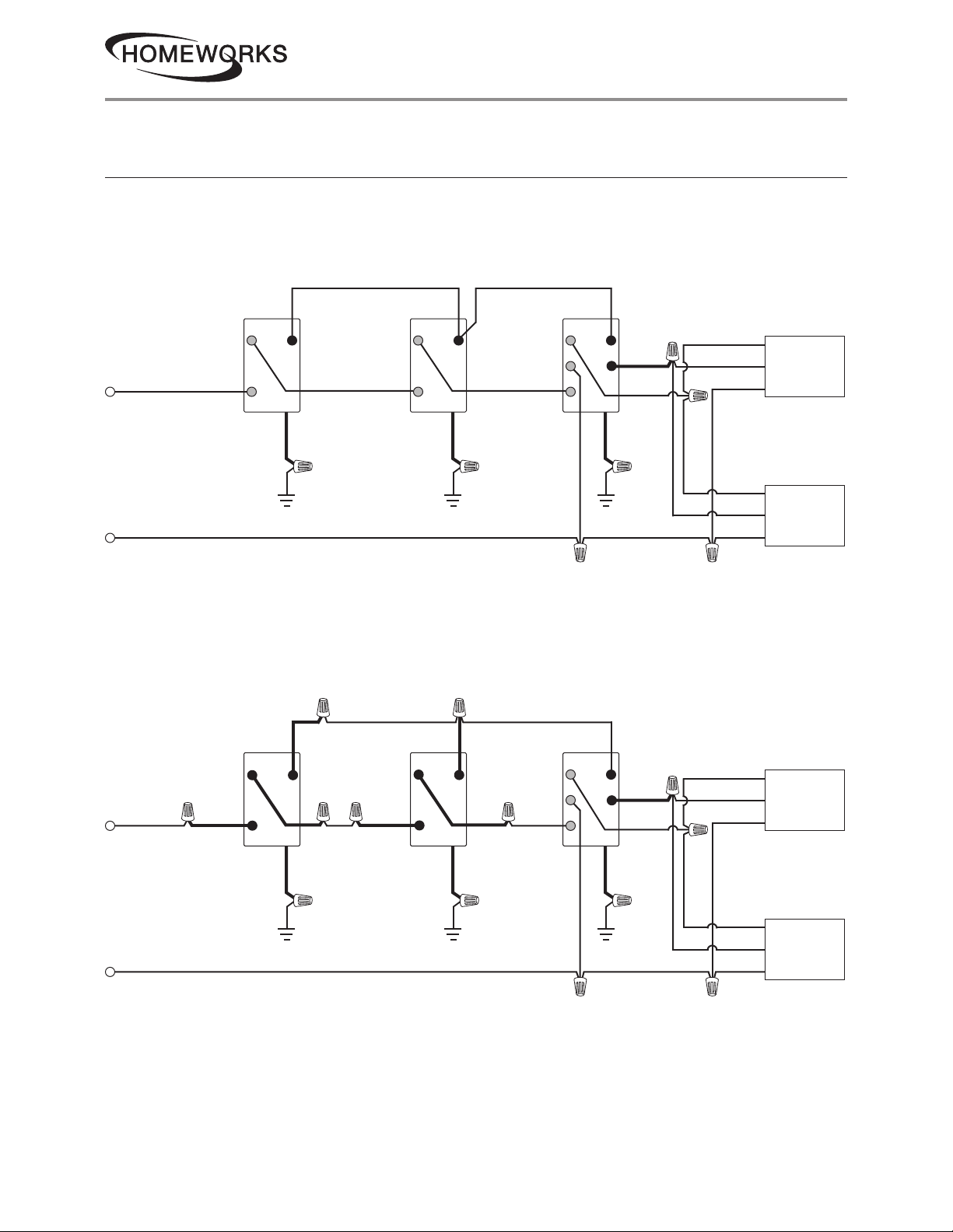
Wiring Diagrams (continued)
Wiring Diagram 7
Multi-Location Fluorescent Dimmer Installation
-F6AN with HQD-RD and Lutron Ballast / LED Driver
1,2
(120 V~)
02.10.20369305i
Remote DimmerRemote Dimmer
Line / Hot
120 V~
50 / 60 Hz
Neutral
Wiring Diagram 8
Multi-Location Fluorescent Dimmer Installation
1,2
(277 V~)
-F6AN with HQD-RD-277 and Lutron Ballast / LED Driver
Remote DimmerRemote Dimmer
BrassBrassBrass
Silver
BlackBlackBlack
Dimmer
GroundGroundGround
Dimmer
2
BlueBlueBlue
Orange
GreenGreenGreen
2
Black
Orange
White
Black
Orange
White
Lutron
Ballast / LED
Driver
Lutron
Ballast / LED
Driver
BrassRedRed
Silver
BlackBlackBlack
Line / Hot
277 V~
50/60 Hz
Neutral
Note: Bolded lines in diagrams indicate leads on products.
1
Up to 9 Remote Dimmers / Remote Switches may be connected to the Dimmer / Switch / Fan Speed Controls. Total blue terminal wire
length may be up to 250 ft (76 m), except for -PRO, which is up to 150ft (45 m).
2
Neutral-Wire Dimmers / Switches / Fan Speed Controls must be connected on the Load side of a multi-location installation, except the
-PRO, which can be connected in any position.
BlueBlueBlue
Orange
GreenGreenGreen
GroundGroundGround
Black
Orange
White
Black
Orange
White
Lutron
Ballast / LED
Driver
Lutron
Ballast / LED
Driver
Continued on next page...
Customer Assistance:
14www.lutron.com/support
1.844.LUTRON1 (U.S.A. / Canada)
Page 15
product specifications
HomeWorks Designer RF Maestro Local Controls
Wiring Diagrams (continued)
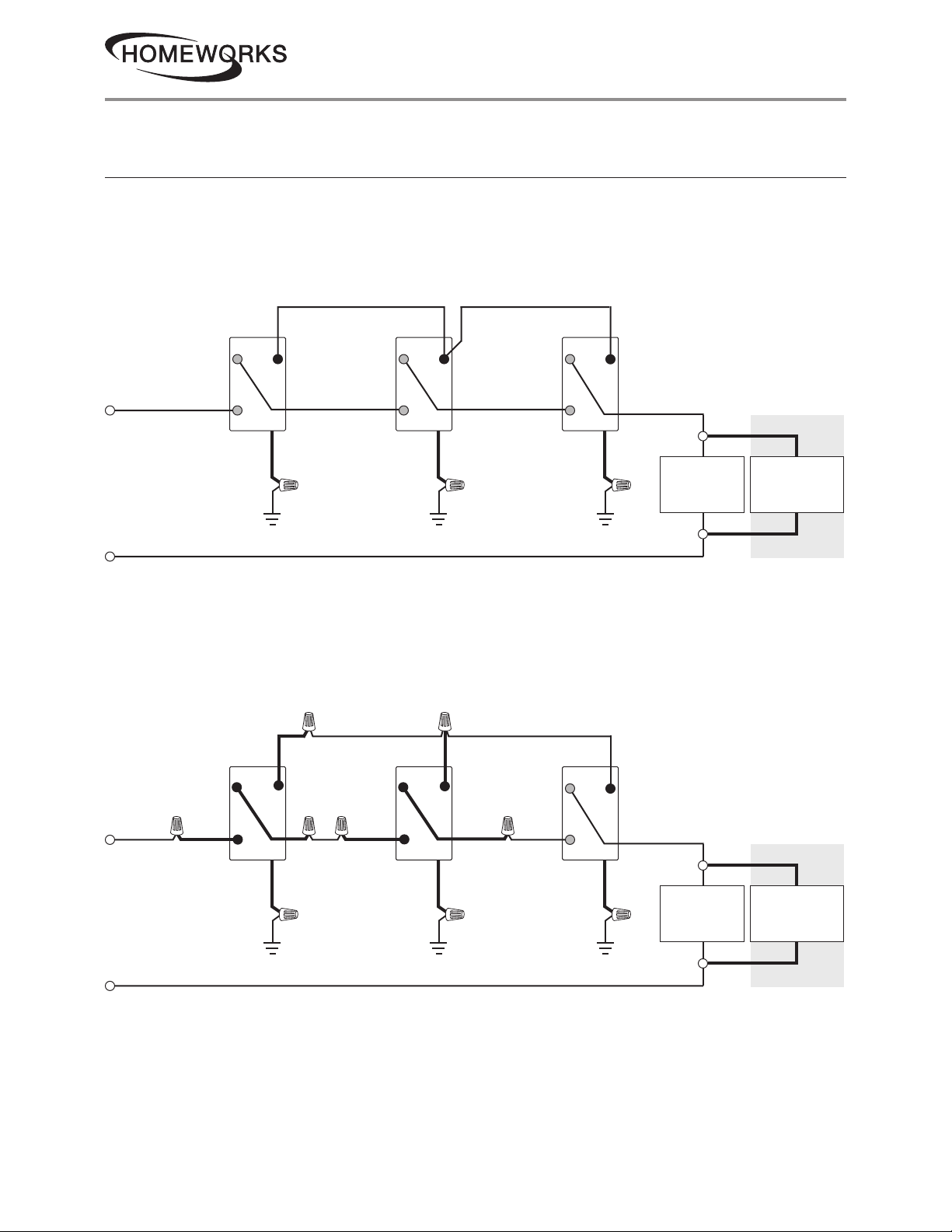
Wiring Diagram 9
Multi-Location 2-Wire Switch Installation1 (120 V~)
-8S-DV with HQD-RS and Optional Shunt Capacitor
02.10.20369305i
Remote Switch
or Switch
Line / Hot
120 V~
50 / 60 Hz
Neutral
Remote Switch
or Switch
Wiring Diagram 10
Multi-Location 2-Wire Switch Installation1 (277 V~)
-8S-DV with HQD-RS-277 and Optional Shunt Capacitor
Remote Switch
or Switch
Remote Switch
or Switch
Switch or
Remote Switch
BrassBrassBrass
BlackBlackBlack
Switch or
Remote Switch
Note: Switch can be
installed in any location
in the circuit.
BlueBlueBlue
Optional
GreenGreenGreen
Load
GroundGroundGround
Shunt
Capacitor
2
Note: Switch can be
installed in any location
in the circuit.
Brass/RedRed/BrassRed/Brass
BlackBlackBlack
Line / Hot
277 V~
50 / 60 Hz
Neutral
Note: Bolded lines in diagrams indicate leads on products.
1
Up to 9 Remote Dimmers / Remote Switches may be connected to the Dimmer / Switch / Fan Speed Controls. Total blue terminal wire
length may be up to 250 ft (76 m), except for -PRO which is 150 ft (45 m).
2
Optional Shunt Capacitor must be installed inside the load fixture or in a separate J-box. Shunt capacitor (LUT-MLC) is included with
8S-DV.
BlueBlueBlue
Optional
GreenGreenGreen
Load
GroundGroundGround
Shunt
Capacitor
Customer Assistance:
15www.lutron.com/support
1.844.LUTRON1 (U.S.A. / Canada)
2
Page 16
product specifications
HomeWorks Designer RF Maestro Local Controls
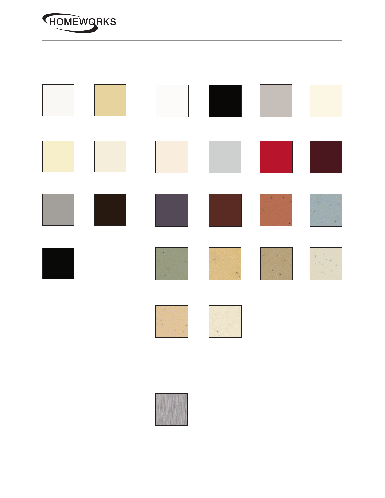
Colors and Finishes
Gloss Finishes Satin Finishes
02.10.20369305i
White
WH
Almond
AL
Gray
GR
Black
BL
Ivory
IV
Light Almond
LA
Brown
BR
Snow
SW
Eggshell
ES
Plum
PL
Greenbriar
GB
Midnight
MN
Palladium
PD
Sienna
SI
Goldstone
GS
Taupe
TP
Hot
HT
Terracotta
TC
Mocha Stone
MS
Biscuit
BI
Merlot
MR
Bluestone
BG
Stone
ST
• Due to printing limitations, colors
and finishes shown cannot be
Desert Stone
DS
For the latest color offerings see our website:
http://www.lutron.com/satincolors
Limestone
LS
guaranteed to perfectly match
actual product colors.
• Color chip keychains are available
for more precise color matching:
Gloss Finishes: DG-CK-1
Metal Finish (wallplate only)
When using Stainless Steel wallplates,
it is recommended that you order the
control in Midnight (MN).
Satin Finishes: SC-CK-1
Stainless Steel
SS
Lutron, Claro, Hi-Lume Compact SE, Eco-10, EcoSystem, FASS, Hi-Lume, HomeWorks, Maestro, and Satin Colors are trademarks or registered
trademarks of Lutron Electronics Co., Inc. in the US and/or other countries.
All other product names, logos, and brands are property of their respective owners.
Customer Assistance:
16www.lutron.com/support
1.844.LUTRON1 (U.S.A. / Canada)
 Loading...