

Homewood LODG0806DSL-1AA Instruction manual
Brigstock Road, Wisbech PE13 3JJ
TOOLS REQUIRED
● Hammer
● Step ladder
● Sand paper
● Battery-powered drill/screwdriver
● 8mm drill
● Pencil
● Tape measure
● Gloves
● Sharp knife and saw
Assembly of Lodge Playhouse
Adult Assembly Only - do not attempt to modify this building
Thank you and congratulations on the purchase of y
We believe that this product will give you many years of excellent service. This is a
natural product manufactured to a high standard therefore if you have any queries or
experience any difficulties then please contact our customer service hotline on
01945 465 295.
Normal office hours: 8.30 am to 5.00 pm Monday to Friday.
Preparation of base
We recommend that the base onto which your building will stand should be at least
75mm larger in each direction than the total floor size of the building.
Floor area of the building: 2390x2690 (8’x9’) including verandah.
Total height clearance: 2606mm
The chosen position in your garden for the siting of the building should be excavated to
a depth of 75mm to allow a base of sand, on to which paving slabs can be evenly laid -
THEY MUST BE LEVEL AND FIRM.
Treatment/care of your Garden Building
Treat with a suitable decorative wood finish immediately. We recommend that all timber
pieces be treated again prior to assembly and again within 3 months of assembly. We
further recommend that all pieces are treated again at least annually or as frequently as
the instructions on the product used recommends.
We would suggest that all wall panels be treated in an upside-down position to allow
the finish/treatment to ingress into the tongue and groove jointing.
We would also remind you that you would rarely (if ever) be able to re-treat the
underside of the floor following assembly. We strongly recommend that the underside
of the floor is treated an absolute minimum of twice (not including pre-treatment).
Garden buildings are not waterproof, therefore on assembling building we
recommend using a silicon based sealant between wall panels and between wall
panels and floor.
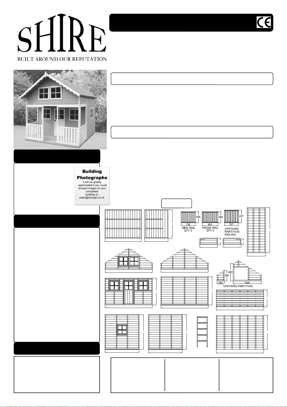
Parts List
our Shire garden building.
EXTERNAL VIEW OF PANELS
IMPORTANT!
PLEASE READ PRIOR TO ASSEMBLY OF
THE BUILDING
EVERY PRECAUTION IS TAKEN TO
ENSURE THAT YOUR BUILDING HAS NO
ELEMENT INCORRECTLY PLACED OR
POSSIBLY HAZARDOUS, HOWEVER
PRIOR TO USE PLEASE CHECK ALL
SURFACES FOR THE FOLLOWING:
1 RAISED GRAIN, SPLINTERS: sand
down timber to smooth fin ish
2 NAIL/SCREW/PIN HEADS PROUD: tap
home to be flush with surface of timber
3 DAMAGED SCREW HEADS
RESULTING IN SHARP SPLINTERS OF
METAL: replace
4 SHARP ENDS OF NAILS/ SCREWS/
PINS PROTRUDING THROUGH THE
PANEL: remove and reposition.
5 ENSURE ALL PARTS ARE SECURED
AGAINST REASONABLE FORCE:
remove and refit
6 ENSURE THERE ARE NO LOOSE
PARTS: remove and refit/discard
We recommend that protective
gloves be worn throughout
PLEASE NOTE
Wood is a natural product and is therefore
prone to changes in appearance, including
some warping, movement and splitting,
particularly during unusual climatic conditions
(long hot or wet spells of weather). As a natural
occurrence this is not covered by a guarantee.
1842
ROOF PANEL - QTY 2
2390
FRONT GABLE
2390
FRONT PANEL
1828 1828
1722
WINDOW SIDE PANEL
QTY DESCRIPTION
4 Frame 44x44x1319mm
4 Frame 44x70x1319mm
4 Frame 44x44x820mm
4 Frame 44x70x889mm
24 Glazing
96 Beading
1182
ROOF PANEL - QTY 2
1404
1722
PLAIN SIDE PANEL
1 Ring handle
1 Wooden knob
2 Vents
2 Fascia profiled
2 Fascia plain
2 Diamonds
52 80mm screws
1514
BACK GABLE
BACK PANEL
2390
2390
900
LH UPSTAIRS
SIDE PANEL
LADDER
342
900
RH UPSTAIRS
SIDE PANEL
1488
2390
VERANDAH FLOOR
2390
FLOOR PANEL
104 60mm screws
1 45mm flat head screw
4 25mm black screws
50 40mm nails
250 Felt nails
192 15mm panel pins
2 Felt roll 6.4mtr x 1mtr
2390
304
934
UPSTAIRS FLOOR
900
1790
22/07/08
A Floor & Walls
Remove all travel protection blocks from
bottom edge of panels.
1. Ensure that your base is firm and
absolutely level.
2. Lay floor of building on base.
3. Pre drill panels in 2
places, top and bottom.
4. Place back panel onto
floor ensuring the cladding has overhung the
floor. The front and back
panels extend from floor
edge to floor edge.
5. Place side panel next to back panel and
join together from the inside using 2 x 60 mm
screws
6. Place other side in position and join to back
panel from the inside using 2 x 60 mm
screws.
1. Place two 44 x 44 x 820 mm pieces of
framework on a flat level surface. Position two
44 x 44 x 1319 mm pieces of framework
between the 820 mm pieces. Secure together
using 4 x 80 mm screws, one at each end.
2. Position side rail within framework. Secure
together through the frame into railing framework at the top and bottom using 2 x 80 mm
screws per side.
3. Repeat for other side rail.
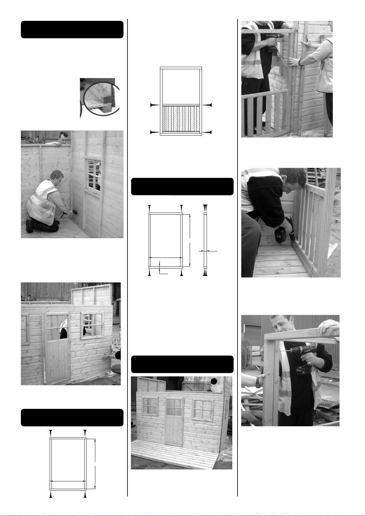
C Verandah Front Railing
1. Place two 44 x 70 x 889 mm pieces of
framework on a flat level surface. The 44 mm
side will be facing upwards. Position two 44 x
70 x 1319 mm of framework inside the 889
mm pieces. Secure together using 8 x 80 mm
screws, two per end.
2. Secure front rail within the frame as per
side rail.
3. Repeat for other front rail.
889
44
1319
SIDE
VIEW
70
2. Place side railing against front of building
inline with edge of verandah floor. Secure to
front panel of using 2 x 60 mm screws, one at
the top and one at the bottom.
3. Secure side railing to verandah floor
through floor bearers using 2 x 60 mm
screws. You will need to position the screws
at an angle.
4. Repeat for other side rail.
7. Place front panel in position and join to
side panels from the inside using 2 x 60 mm
screws per side.
B Verandah Side Railing
820
1319
D Verandah Assembly
1. Position verandah floor against front of
building.
5. Place front railing against side railing,
ensuring rail is flush and square. Secure rails
together through side railing using 2 x 60 mm
screws, one at the top and one at the bottom.
6. Secure front railing to verandah floor
through floor bearers using 2 x 60 mm
screws. Again you will need to position the
screws at an angle.
7. Repeat for other front rail.
 Loading...