

Homewerks Worldwide 7130 06 BTN User Manual
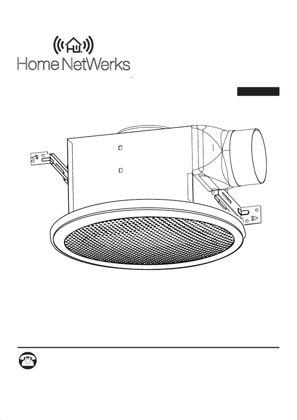
VENTILATING BATH FAN
WITH BLUETOOTH®
Home NetWerks
SIMPLE SOLUTIONS FOR A SMARTER HOME
U.S. Pat. No. 9,398,357
SPEAKER
MODEL #7130-06-BT
Español p. 14
The BLUETOOTH® word mark and logos are registered trademarks owned by BLUETOOTH SIG, Inc. and any use of the said
mark by Homewerks Worldwide is under license. Other trademark and trade names are those of their respective owners.
Questions, problems, missing parts? Before returning to your retailer, call our customer
service department at 1-877-319-3757, 8 a.m. - 5 p.m., CST, Monday - Friday.
READ AND SAVE THESE INSTRUCTIONS
www.homewerksww.com
03-10-2017
TABLE OF CONTENTS
Product Specifications ........................................................................................................................2
FCC Compliance ................................................................................................................................2
Package Contents ..............................................................................................................................3
Hardware Contents.............................................................................................................................3
Safety Information ..............................................................................................................................4
Preparation ......................................................................... ...... .. ........................................................4
New Construction Assembly Instructions ...........................................................................................6
Existing Construction Assembly Instructions ......................................................................................7
BLUETOOTH
® Speaker Fan Grille Installation ...................................................................................9
Pairing Light Switch with Fan ...........................................................................................................10
Pairing your BLUETOOTH
BLUETOOTH
® Speaker and Fan Operation.....................................................................................10
® Device to the Speaker .........................................................................10
Care and Maintenance ..................................................................................................................... 11
Troubleshooting .................................. ....................................... .. .....................................................13
Warranty ...........................................................................................................................................13
PRODUCT SPECIFICATIONS
SPECIFICATIONS
Airflow: 100 CFM
120V, 60Hz
Duct diameter : 4 in.
Motor power consumption: 28.8 W
Exhaust fan speed: 920 RPM
Weight: 11.88 lbs.
SPECIFICATIONS
Sound output: 1.5 Sones
FCC COMPLIANCE
This equipment complies with FCC RF radiation exposure limits. Keep
minimum 20cm away between the radiator and body.
This device complies with part 15 of the FCC rules. Operation is subject
to the following two conditions: (1) this device may not cause harmful
interference, and (2) this device must accept any interference received,
including interference that may cause undesired operation.
NOTE: The manufacturer is not responsible for any radio or TV
interference
caused by unauthorized modifications or changes to this equipment. Such
modifications or changes could void the user’s authority to operate the
equipment.
NOTE: This equipment has been tested and found to comply with the
limits for a Class B digital device, pursuant to part 15 of the FCC Rules.
These limits are designed to provide reasonable protection against
harmful interference in a residential installation. This equipment generates
uses and can radiate radio frequency energy and, if not installed and
used in accordance with the instructions, may cause harmful interference
to radio communications. However, there is no guarantee that interference
will not occur in a particular installation. If this equipment does cause
harmful interference to radio or television reception, which can be
determined by turning the equipment off and on, the user is encouraged to
try to correct the interference by one or more of the following measures:
– Reorient or relocate the receiving antenna.
– Increase the separation between the equipment and receiver.
– Connect the equipment into an outlet on a circuit different from that to
which the receiver is connected.
– Consult the dealer or an experienced radio/TV technician for help.
Changes or modifications made to this equipment not expressly approved by
Homewerks Worldwide, LLC may void the FCC authorization to operate
this equipment.
2
www.homewerksww.com
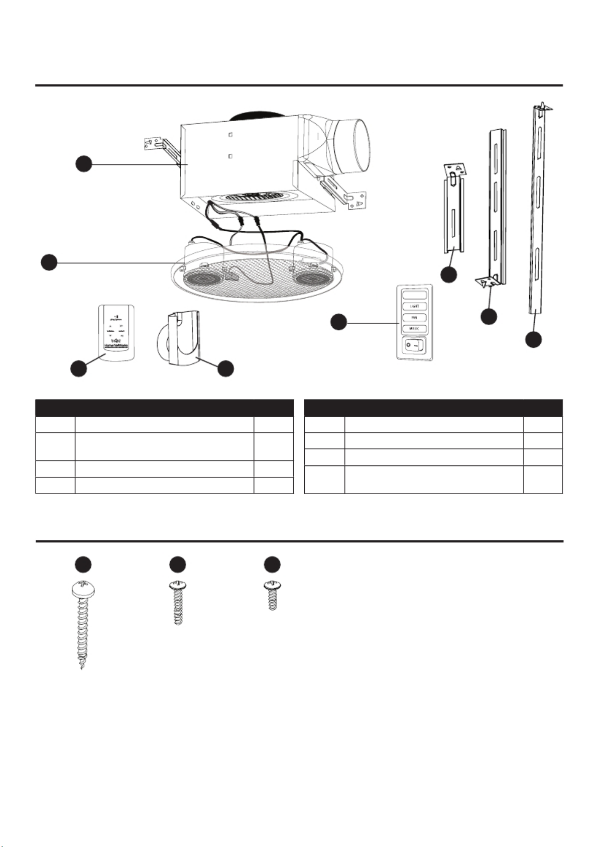
PACKAGE CONTENTS
A
B
F
NIGHT LIGHT
C
D
E
H
PART
A
B
C
D
DESCRIPTION
Fan body
Grille w/BLUETOOTH
speakers and light
Suspension Bracket I
Suspension bracket II
G
®
QTY
1
1
1
1
PART
E
F
G
H
DESCRIPTION
Suspension Bracket III
Wall switch
Remote control
Remote control holder and
suction cup
QTY
1
1
1
1
HARDWARE CONTENTS (not actual size)
AA
BB
CC
M4x30
Qty. 8
www.homewerksww.com
M4x12
Qty. 2
M4x10
Qty. 1
3

SAFETY INFORMATION
Please read and understand this entire manual before attempting to assemble, operate or install
the product.
Always disconnect the power supply prior to servicing the fan, motor or junction box.
1.
Installation work must be carried out by a qualified person(s) in accordance to all local and
2.
safety codes including the rules for fire-rated construction.
Follow all local building, safety and electrical codes as well as NEC (National Electrical Code)
3.
and OSHA (Occupational Safety and Health Act).
Electric Service supply must be 120 volts, 60 hertz.
4.
5.
This unit must be properly grounded.
6.
Do not bend or kink the power wires.
7.
Exercise care to not damage existing wiring when cutting or drilling into walls or ceilings.
8.
Sufficient air supply is required for proper combustion and the exhaustion of gases through
the chimney (flue) of fuel burning equipment to prevent back-drafting. See the standards of
NFPA (National Fire Protection Association) and ASHRAE (American Society for Heating
Refrigeration and Air Conditioning Engineers) and the local building code authorities.
Do not use this fan with any solid state control device, such as a remote control, dimmer switch,
9.
or certain timers. Mechanical timers are not solid state devices.
10. This ventilation fan is approved for use over a bathtub or shower when installed in a GFCI
protected circuit. Do not use fans over a bathtub or shower that are not approved for that
application and marked accordingly.
11. Do not install in a cooking area.
12. Do not use to exhaust hazardous or explosive vapors.
13. Fans should always be vented to the exterior and in compliance with local codes.
14. Do not install in a ceiling with insulation greater than R42.
15. Duct work should be installed in a straight line with minimal bends.
16. Duct work size must be the same size as the discharge and should not be reduced. Reducing
the duct size may increase fan noise.
17. Prior to service or cleaning this unit, shut off power supply at the panel and lock to
prevent the power from being turned on. If the panel cannot be locked, clearly mark
the panel with a warning tag to prevent the power from being turned on.
18. Use this unit in the manner intended by the manufacturer. If you have any questions. Please
call customer service.
19. The fan is intended to be mounted at least 7 ft. above the floor.
PREPARATION
Before beginning assembly of product, make sure all parts are present. Compare parts with package
contents list and hardware contents. If any part is missing or damaged, do not attempt to assemble
the product. Contact customer service for replacement parts at 1-877-319-3757, 8 a.m. - 5 p.m., CST,
Monday - Friday.
4
www.homewerksww.com
PREPARATION
Tools Required for Assembly (not included): Hammer, Flathead Screwdriver, Wire Nuts, Nails, Duct Tape,
Phillips Head Screwdriver, Utility Knife or Drywall Saw,
Helpful Tools (not included): Electric Drill, Drill Bits
WARNING: Turn off electricity at breaker box before beginning installation.
Carefully remove unit from carton.
*Before removing your current ventilation unit, verify your switch box on the wall has the required supply
wires necessary for this install. These supply wires are power/black and nuetral/white (refer to right
side of wiring diagram below) at the switch. If you do not see both of these wires, consult a licensed
electrician for install.
Check area above installation location to be sure that wiring can run to the planned location and that
duct work can be run and the area is sufficient for proper ventilation.
Inspect duct work and wiring before proceeding with installation.
Before installation, provide inspection and future maintenance access at a location that will not interfere
with installation work.
You may need the help of a second person to install this fan; one person on the attic side and one on
the room side.
Note: Installations may vary depending on how the previous bath fan was installed. Supplies necessary
for the installation of your bath fan are not all included; however, most are available at your local
home improvement or hardware store.
DIMENSIONS REQUIREMENTS
Ceiling
Opening (L)
9.4 in. 9.4 in. 7.4 in.
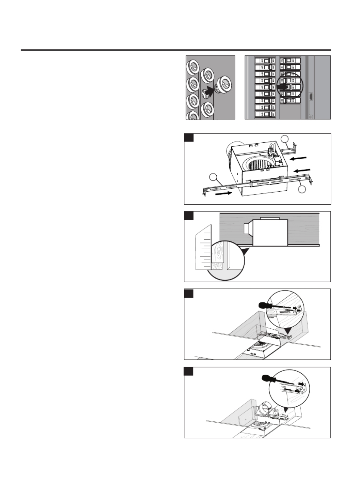
WIRING DIAGRAM
All wiring must be connected for full functionality. Do not use metal wall plate with switch.
www.homewerksww.com
Ceiling
Opening (W)
green ground
black switch
connection
white neutral
Ceiling
Opening (H)
green ground
black switch
connection
Dimension (L)
5
Housing
9.25 in. 9.25 in. 7.375 in.
Housing
Dimension (W)
Dimension (H)
black power
house/white neutral
Housing
ASSEMBLY INSTRUCTIONS
NEW CONSTRUCTION – ATTACHING TO THE
JOIST
BEFORE INSTALLATION
Turn off power source. Review all safety
precautions.
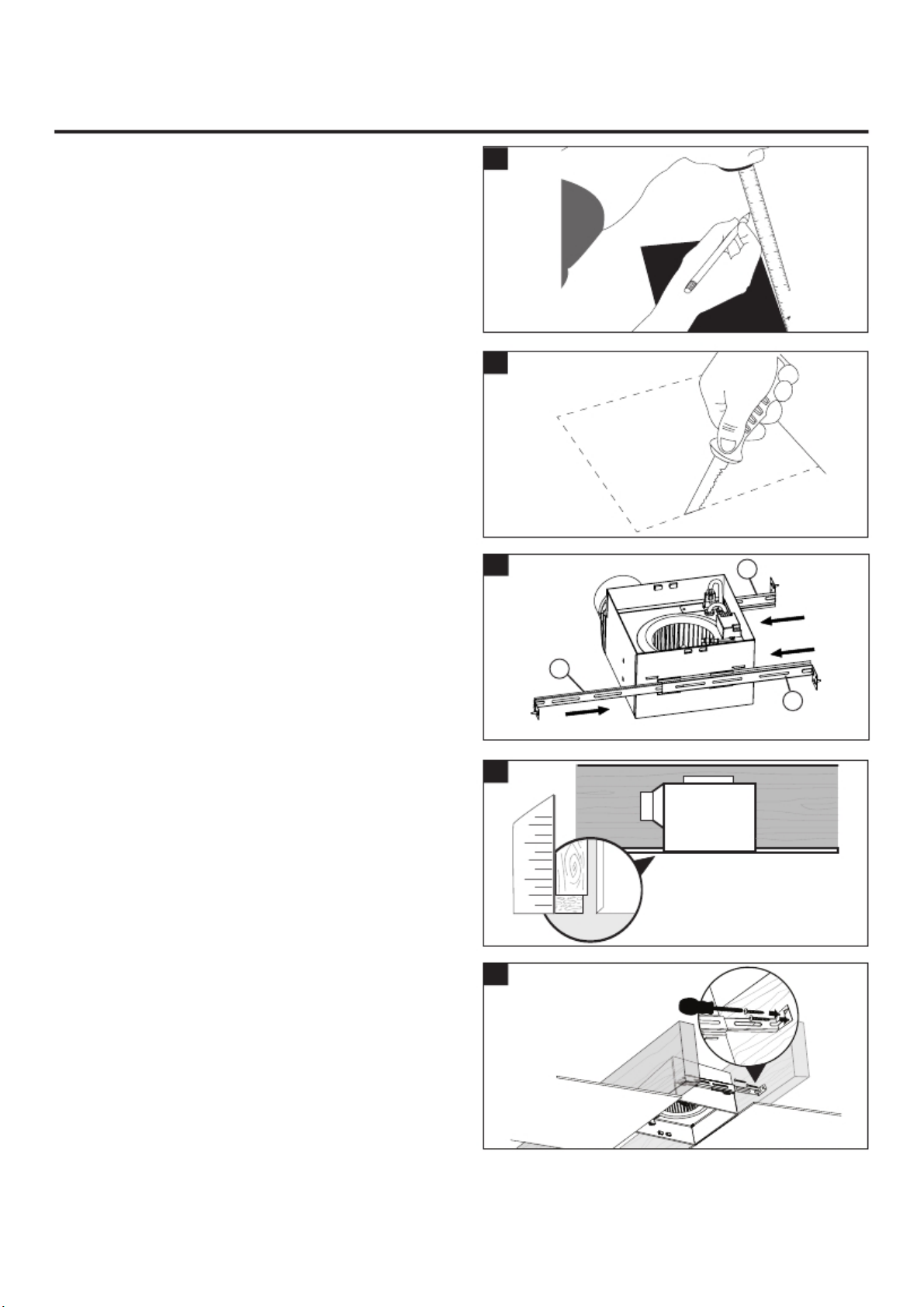
1. Insert suspension bracket onto fan housing
1
C
using suspension bracket I (C) and II (D). If
spacing between joists is 21.5 in. to 23.5 in.
attach suspension bracket III (E).
E
2. Position fan housing so edge of fan is flush
with sheetrock. Do not flush mount housing
with joist.
3. Secure the fan housing t o joist wit h sus pe ns io n
brackets using (AA) (inclu ded ). (J o ist spac ing of
less than 21.25 in.)
4. Mounting with joist spacing of 21.25 in. to
23.5in.
6
2
3
4
1 2
www.homewerksww.com
D
ASSEMBLY INSTRUCTIONS
5. Secure the suspension bracket I (C) to fan
5
housing using screw (CC) (included).
Secure suspension brackets (D & E) with
screws (BB) (included).
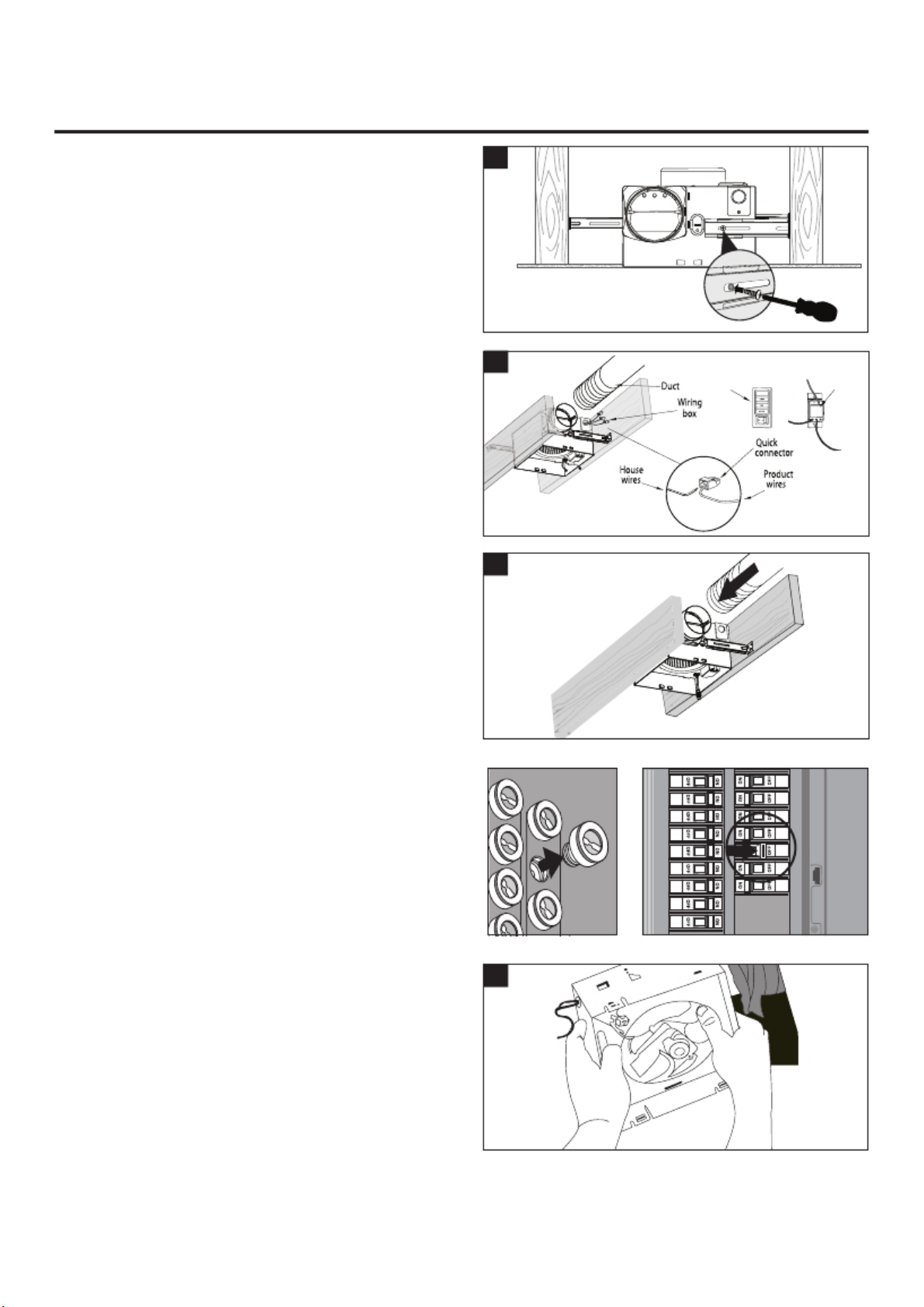
6. Remove junction box cover. As shown in wiring
diagram on page 5, using quick connect ports
connect house wires to switch and fan.
Note: Do not use metal wall plate with the
switch, as it may cause interference with the
fan operation.
7. Connect a 4 in. circular duct and vent to the
outside. Secure it with duct tape or clamp.
Turn on power source.
EXISTING CONSTRUCTION – ACCESSIBLE
FROM ABOVE
BEFORE INSTALLATION
Turn off power source. Review all safety
precautions.
1. Remove existing fan.
www.homewerksww.com
7
6
Wall
switch
Green Wall switch
wire back view
NIGHT LIGHT
Black
wire
Black
wire
7
1
ASSEMBLY INSTRUCTIONS
2. Measure the opening to assure it is large
enough to accommodate the new fan
housing (9.4 in. x 9.4 in.).
3. If this fan is not replacing an old fan be sure
2
3
to cut a 9.4 in. x 9.4 in. opening for the fan
housing.
4. Insert suspension bracket onto fan housing
4
9.4"
C
using suspension bracket I (C) and II (D). If
spacing between joists is 21.5 in. to 23.5 in.
attach suspension bracket III (E).
E
5. Position fan housing so edge of fan is flush
with sheetrock. Do not flush mount housing
with joist.
6. Secure the fan housing t o joist wit h sus pe ns io n
brackets using (AA) (included). (Joist spacing of
less than 21.25 in.)
8
5
1 2
6
www.homewerksww.com
D
 Loading...