

Homewerks HTR-REV02-L Instruction Manual
Instructions
www.homewerksww.com
Eective/Rev. date: March 15, 2012
1
Model #HTR-REV02-L
Item# 398999
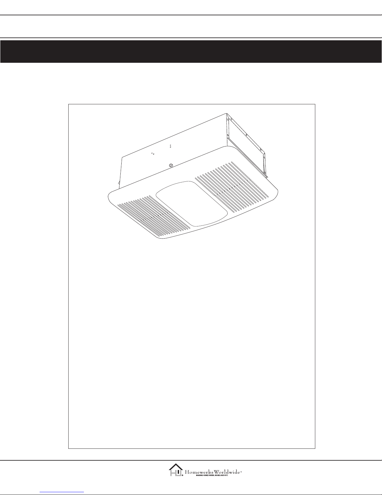
Ventilating Bath Fan with
Heater and Light
READ AND SAVE THESE INSTRUCTIONS:
Please read these instructions carefully before attempting to install, operate or service the
ventilating fan. Failure to comply with instructions could result in personal injury and /or
property damage. Please retain this booklet for future reference.
Table of Contents
Please read prior to installing this fan........................................................................................................2
Supplied parts ....................................................................................................................................................2
Description ..........................................................................................................................................................3
Dimensions .......................................................................................................................................................... 3
Wiring diagram...................................................................................................................................................4
Specications ......................................................................................................................................................4
Dimensions .......................................................................................................................................................... 4
Unpacking ............................................................................................................................................................5
General safety information & warnings.................................................................................................5-6
Installation ....................................................................................................................................................... 6-8
Use and Care ....................................................................................................................................................... 9
Warranty .............................................................................................................................................................10
Warning: This fan is not intended for vertical, wall-mount installation.
Instructions
www.homewerksww.com
Eective/Rev. date: March 15, 2012
2
Model #HTR-REV02-L
Item# 398999
PLEASE READ PRIOR TO INSTALLING THIS FAN
This line of ventilating fans employs state-of-the-art technology. Please read this entire
instruction booklet prior to installation to realize the benets this fan oers.
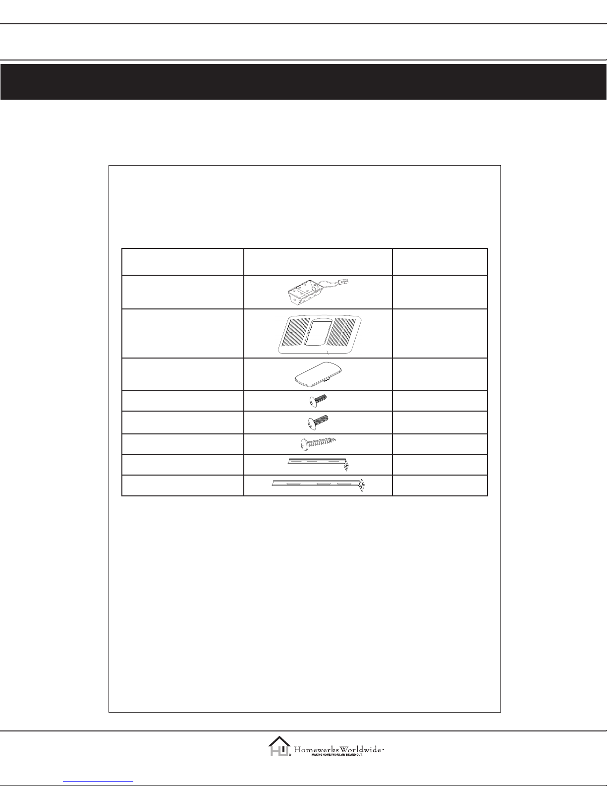
SUPPLIED PARTS
PART NAME APPEARANCE QUANTITY
Reector Assembly 1
Grille 1
Light Lens 1
Short Machine Screw 4
Medium Machine Screw 1
Long Wood Screw 8
Suspension Bracket I – 12" 2
Suspension Bracket II – 14" 2
Instructions
www.homewerksww.com
Eective/Rev. date: March 15, 2012
3
Model #HTR-REV02-L
Item# 398999
DESCRIPTION
This ventilating fan uses a low-noise, motor-driven fan. The motor is designed and
manufactured to have an extended service life and operates very eciently. There
is a thermal cut-o for safety.
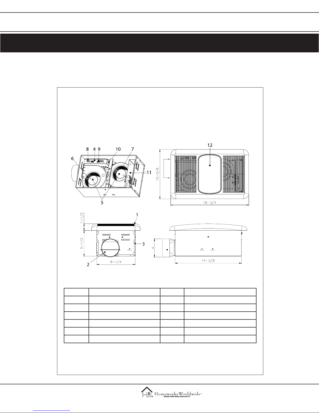
LINE ART/DIMENSIONS
NO. Part Name NO. Part Name
1 Grille 7 Blower Wheel Heater
2 Damper 8 Fan Receptacle
3 Fan Body 9 Light Receptacle
4 Junction Box 10 Heater Receptacle
5 Motor 11 Heater
6 Blower Wheel Fan 12 Light Lens
Instructions
www.homewerksww.com
Eective/Rev. date: March 15, 2012
4
Model #HTR-REV02-L
Item# 398999
WIRING DIAGRAM
POWER
NEUTRAL
GROUND
SPECIFICATIONS
Model No. Air
direction
V Hz Duct
diameter
(inches)
Noise
(sone)
Power
consumption
(W)
Heating
element (coil)
wattage
Air deliver
at 0.1" WG
(cfm)
HTR-REV02-L Exhaust &
Circulation
120 60 4 3.0 1400 1300 80
DIMENSIONS
Ceiling
Opening L
Ceiling
Opening W
Ceiling
Opening D
Housing
Dimension L
Housing
Dimension W
Housing
Dimension D
14-5/8 8-1/2 5-1/2 14-3/8 8-1/4 5-1/2
Be careful to cut hole exactly. If the hole is too big the fan grille will not hide it.

Instructions
www.homewerksww.com
Eective/Rev. date: March 15, 2012
5
Model #HTR-REV02-L
Item# 398999
UNPACKING
Carefully remove unit from carton. Remove the foam in the housing. Refer to the Supplied
Parts list on page 2 to verify that all parts are present.
GENERAL SAFETY INFORMATION & WARNINGS
1. Electric Service supply must be 120V 60Hz.
2. Follow all local safety and electrical codes as well as NEC (National Electrical Code) and OSHA
(Occupational Safety and Health Act).
3. This unit must be properly grounded.
4. Always disconnect the power supply prior to servicing the fan, motor or junction box.
5. Do not bend or kink the power wires. Protect from sharp edges, oil, grease, hot surfaces,
chemical or other objects.
6. Do not install where the room air temperature will exceed 40ºC (104ºF).
7. Do not install over a tub or mount in a shower stall enclosure.
8. Do not use to exhaust hazardous or explosive vapors.
9. Do not install in a cooking area.
10. Do not install this fan vertically in a wall.
11. Use this unit in the manner intended by the manufacturer. If you have any questions please call
the manufacturer (customer service number located on last page).
12. Installation work must be carried out by a qualied person(s) in accordance to all local and safety
codes including the rules for re-rated construction. For use in non-re rated installations only.
13. Sucient air supply is required for proper combustion and the exhaustion of gases through the
chimney (ue) of fuel burning equipment to prevent back-drafting. See the standards of NFPA
(National Fire Protection Association) and ASHRAE (American Society for Heating Refrigeration
and Air Conditioning Engineers) and the local building code authorities.
14. Exercise care to not damage existing wiring when cutting or drilling into walls or ceilings.
15. Fans should always be vented to the exterior and in compliance with local codes.
16. Do not use this fan with any solid state control device; such as a dimmer switch. Solid-state
controls may cause harmonic distortion, which can cause a motor humming noise.
17. Prior to service or cleaning this unit, shut o power supply at the panel and lock to
prevent the power from being turned on. If the panel cannot be locked, clearly mark
the panel with a warning tag to prevent the power from being turned on.
18. Do not install in a ceiling with insulation greater than R40. (This is required for installations in
Canada only.)
19. Duct work should be installed in a straight line with minimal bends.
20. Duct work size must be a minimum of the discharge and should not be reduced.
Reducing the duct size can increase fan noise.
21. This ventilating bath fan is intended for residential use only in 1-2 family dwellings.
22. Never place a switch where it can be reached from a tub or shower.
23. Make sure that the electric service supply voltage is AC 120V, 60Hz.
24. Always disconnect the power source before working on or near the unit.
25. This unit is designed and tested to be a supplemental heater for use with a timer or a switch.
It is not intended to be used as the primary source of heat and controlled by a thermostat.
Instructions
www.homewerksww.com
Eective/Rev. date: March 15, 2012
6
Model #HTR-REV02-L
Item# 398999
26. To avoid motor bearing damage and noisy and/or unbalanced impellers, keep drywall spray,
construction dust, etc. o power unit.
27. Provide a separate 20 AMP circuit.
28. This product is designed for ceiling installation only. DO NOT MOUNT THIS PRODUCT IN
A WALL.
29. Install in ceiling only, at least 6" from any wall.
30. For greatest eciency, install heater so heat is directed toward tub or shower area. Avoid
directing toward walls or windows.
INSTALL THE UNIT
Installing the fan body in an existing building requires an accessible area (attic or crawl
space) above the planned installation location and existing duct and wiring.
CAUTION: Check area above installation location to ensure that:
1. Duct work can be run and the area is sucient for proper ventilation.
2. Wiring can be run to the planned location.
3. No wiring or other obstructions can interfere with installation.
1. Inspect duct work and wiring before proceeding with installation.
2. Before installation provide inspection and future maintenance access at a location that will not
interfere with installation work.
3. Remove ceiling section using dimensions provided on page 4. Be careful to cut hole exactly. If
hole is too big the fan grill will not hide it.
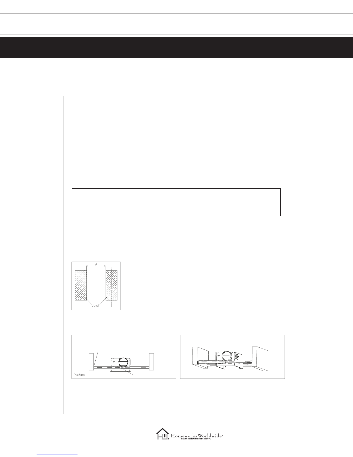
4. Determine the distance between your joists.
Fig. 1
5. Refer to Fig. 2 to mount the fan between the joists.
Long
wood
screws
Short machine screws
Fig. 2
Instructions
www.homewerksww.com
Eective/Rev. date: March 15, 2012
7
Model #HTR-REV02-L
Item# 398999
Fig. 5
5-1. Insert the suspension bracket into the bracket cover of duct side and the back
of the fan body. The brackets adjust to the distance between the joists.
5-2. Insert the fan between joists. Make sure the fan body is level and perpendicular
with the joist, and ush with ceiling surface.
5-3. Allow for thickness of the ceiling board used in your application. DO NOT FLUSH
MOUNT TO JOIST. Fan body should be ush with ceiling board.
5-4. Secure the suspension bracket to joists by using long wood screws.
5-5. Secure the suspension bracket to fan body by short machine screws.
6. Duct connection.
CAUTION: ALL DUCTING MUST COMPLY WITH LOCAL AND NATIONAL BUILDING CODES.
6.1. Snap the damper/duct connector onto housing. Make
sure that tabs on the connector lock into housing slots.
6-2. Insert the duct into the duct connector and tape all
duct work connections to make them secure and air
tight.
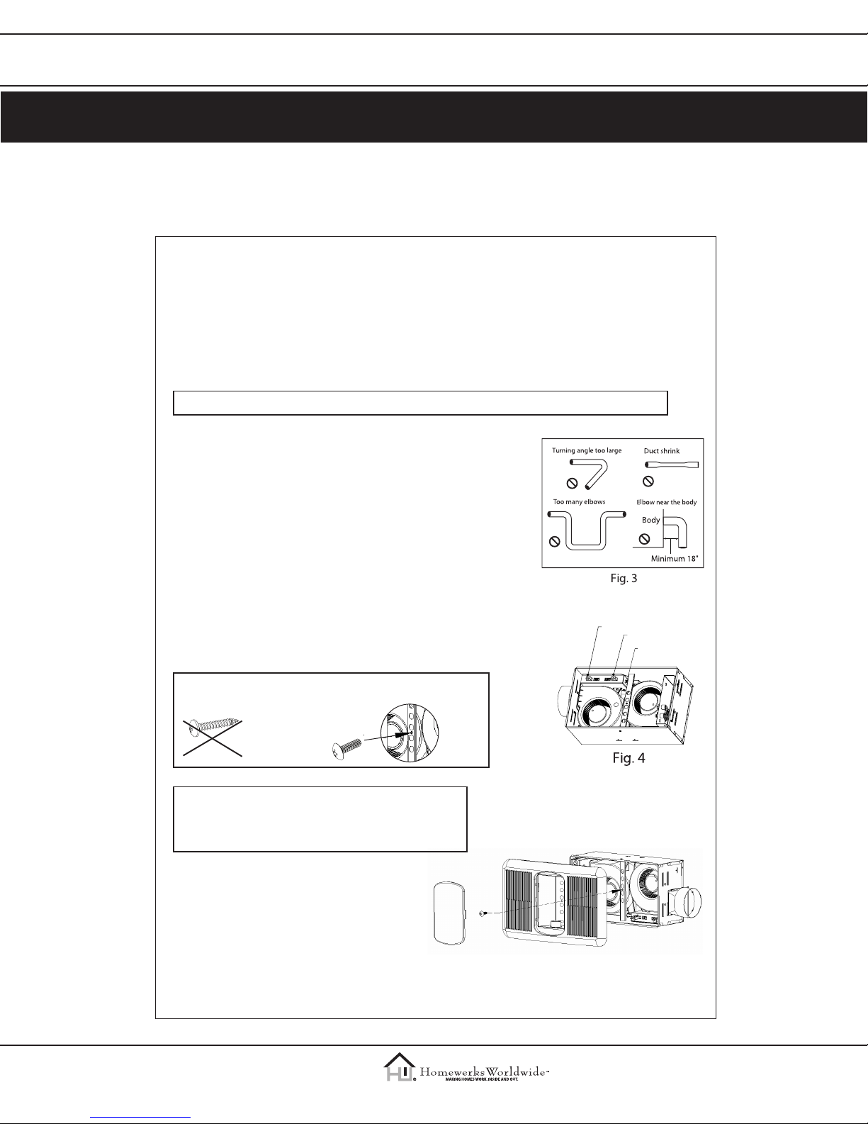
6-3. Do not install the unit where ducts are congured as
shown in Fig. 3.
6-4. Install the duct with a gradient 1°~2° to the outside.
7. Complete the installation.
7.1 Refer to Fig. 4, insert the plug from the heating
unit into the receptacle marked “HEAT”, and the
plug from the fan into the receptacle marked
“VENT”, and the plug from the light into the
receptacle marked “LIGHT”.
7-2. Install light reector into grille by using one medium
machine screw as shown in Fig. 5.
Medium
machine
screw
Long wood
screw
WARNING: DO NOT USE LONG WOOD SCREW IN PLACE
OF MEDIUM MACHINE SCREW.
CAUTION: Install a light bulb 60 watt maximum
(not included).
To save energy use compact ourescent bulbs.
7-3. Install light lens into grille/reector assembly.
Ventilation Fan
Light
Heater
Instructions
www.homewerksww.com
Eective/Rev. date: March 15, 2012
8
Model #HTR-REV02-L
Item# 398999
8. Connect wiring
CAUTION: MAKE SURE POWER IS SWITCHED OFF AT SERVICE PANEL BEFORE STARTING
INSTALLATION.
CAUTION: ALL ELECTRICAL CONNECTIONS MUST BE MADE IN ACCORDANCE WITH LOCAL
CODES, ORDINANCES, OR NATIONAL ELECTRICAL CODE. IF YOU ARE UNFAMILIAR
WITH METHODS OF INSTALLING ELECTRICAL WIRING, SECURE THE SERVICES OF A
QUALIFIED ELECTRICIAN.
WARNING: THIS UNIT MUST BE WIRED ON A SEPARATE 20 AMP CIRCUIT.
WARNING: If your house wires do not match these colors, you must determine what
each house wire represents before connecting and you may need to consult
an electrical contractor to determine this safely.
8-1. Follow all local electrical and safety codes.
8-2. NEVER place a switch where it can be reached from a tub or shower.
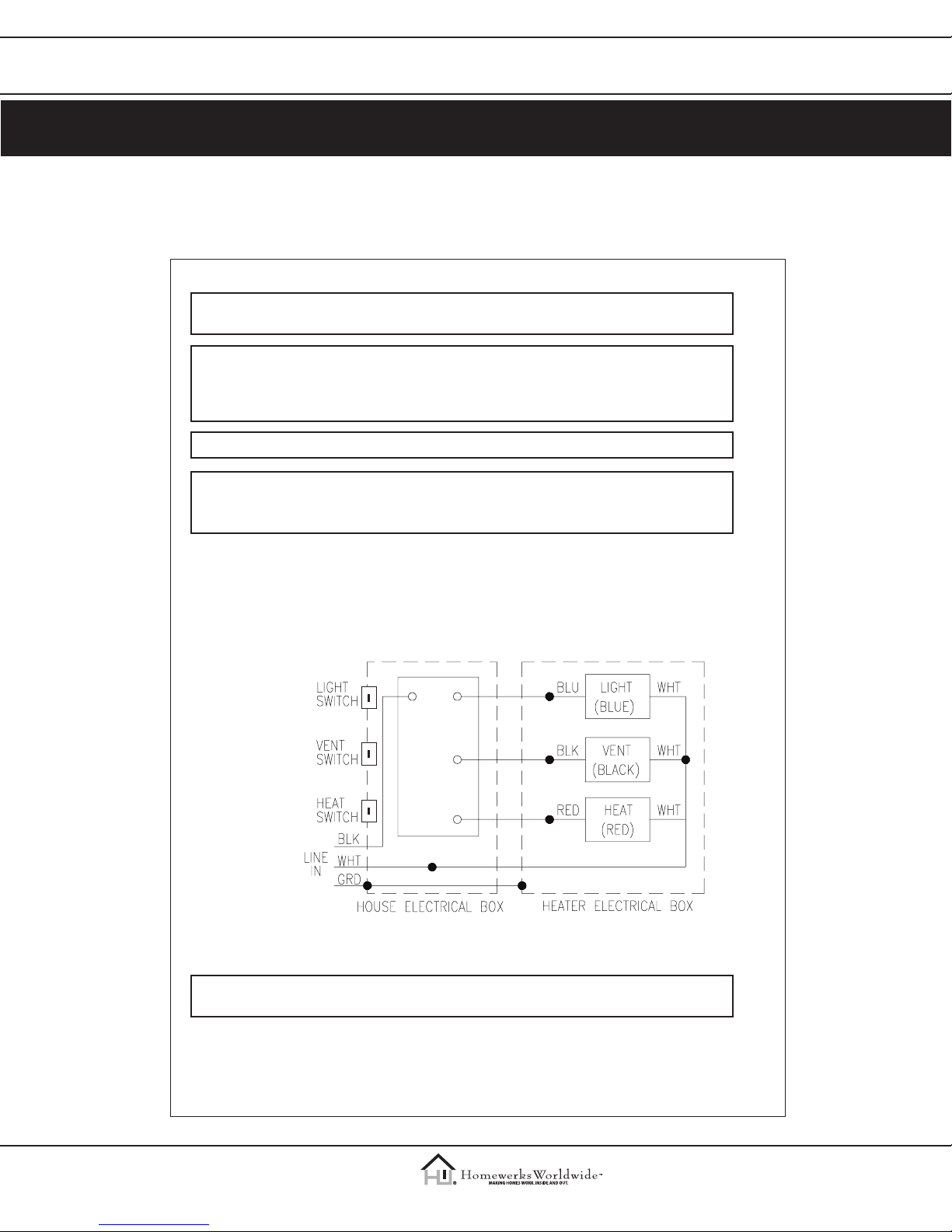
8-3. Connect wires as shown in Fig. 6.
8-4. Using wire nuts, connect house power wires to fan wires.
8-5. 14 AWG (2.1 mm2) is the smallest conductor that shall be used for branch-circuit wiring.
Each power wire (Light, Fan, Heater) must have its own switch to operate independantly.
POWER
NEUTRAL
GROUND
Fig. 6
9. Operation
CAUTION: FAILURE TO SECURE THE REFLECTOR SCREWS MAY RESULT IN A RATTLING
OR HUMMING NOISE.
9-1. Turn on the LIGHT switch to turn on the light bulb.
9-2. Turn on the VENT switch to operate the fan mode.
9-3. Turn on the HEAT switch to operate the heater mode.
Instructions
www.homewerksww.com
Eective/Rev. date: March 15, 2012
9
Model #HTR-REV02-L
Item# 398999
USE AND CARE
CAUTION: MAKE SURE POWER IS SWITCHED OFF AT SERVICE PANEL BEFORE SERVICING
THE UNIT.
TO REPLACE BULB – Remove lens by gently depressing sides and pull down. Use bulb rated up
to 60 watts only.
CAUTION: ALLOW BULBS TO COOL BEFORE REPLACING.
TO CLEAN LENS AND GRILLE – Remove lens as explained above. Remove bulb. Remove screw in
center of reector and lower assembly.
CAUTION: Grille and reector are separate units. Unplug light from receptacle. Plastic parts
can be cleaned with mild, soapy water and dried with soft cloth.
DO NOT USE ABRASIVE CLOTHS, STEEL WOOL PADS, OR SCOURING POWDERS. NEVER USE SOLVENTS,
THINNER OR HARSH CHEMICALS FOR CLEANING THE FAN.
TO CLEAN FAN ASSEMBLY – Unplug fan motor cord from receptacle. Remove retaining screws.
Gently vacuum fan, motor and interior housing. Motor is permanently lubricated and never needs
oiling.
CAUTION: Fan and motor will swing downward when screw is removed. Support this unit
with free hand while removing retaining screw.
TO CLEAN HEATER ASSEMBLY – Unplug heater cord from receptacle. Loosen retaining screws. Place
a screwdriver tip between outer wall of housing and heater exhaust opening. Gently pry outward
until exhaust housing slips o support tip. Gently vacuum fan, motor and interior housing. Motor
is permanently lubricated and never needs oiling.
CAUTION: Unit will swing downward when released. Support with free hand while prying
with screwdriver.
METAL AND ELECTRICAL PARTS SHOULD NEVER BE IMMERSED IN WATER.
 Loading...