

Page 1
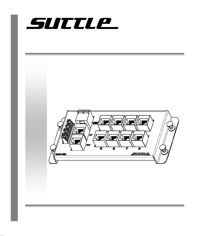
SAM-V8M 8-Port Voice Module
User Guide
1001 East Hwy 212
Hector, MN 55342
www.suttlesoho.com
Toll Free: 1-800-852-8662
Local: 1-320-848-6711
Fax: 320-848-2361
Page 2
1. Introduction
Features
• Conforms to UL standards.
• Accommodates up to 4 telephone service lines.
• Alarm interface is configured for use on service line 1.
• Centralized test port, to verify incoming phone service.
• Supports up to 8 home run terminations.
• Installer-friendly push-lock pin mounting.
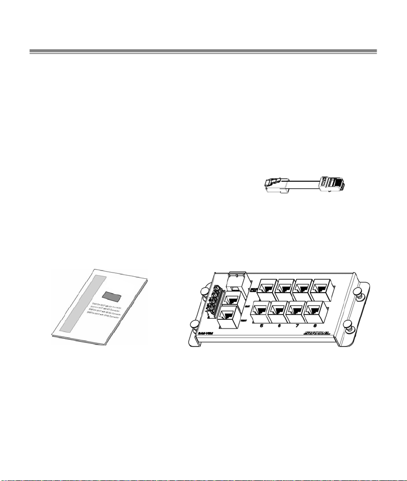
Package Contents
• 8 Port Voice Module
• 3” Jumper Cord
• User Guide
User Guide
Compare the contents of your SAM-V8M with the checklist above. If any item is missing or
(do not discard)
3” Jumper
8-Port
Voice Module
damaged, please contact your local dealer for service.
Cord
Page 3
2. Module Installation
Mounting:
Align the mounting pins with the grid holes on the back of the enclosure. With the
mounting pin plungers in the “out” position, press the unit into the grid in the desired
location, secure by pushing the plungers in.
Terminate Incoming Service Lines:
Run twisted pair cable from the telephone company demarcation point to the 110 IDC
labeled “LINE IN” on the SAM-V8M.
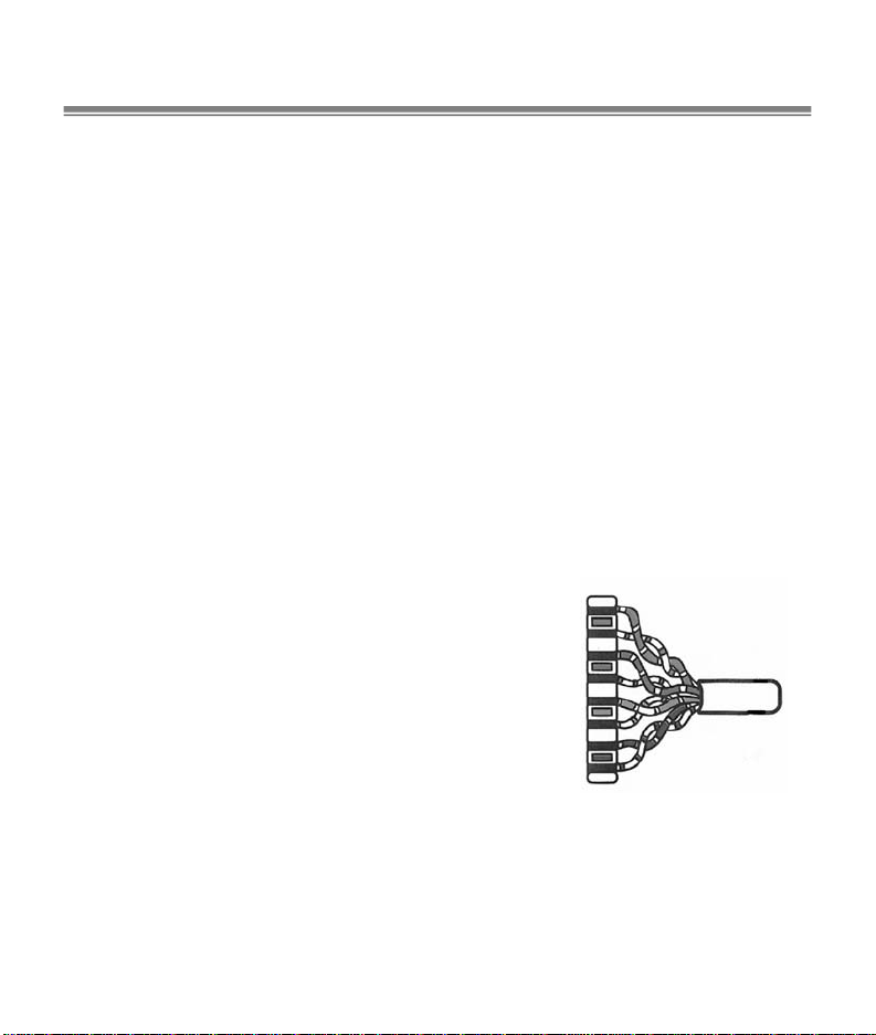
110 IDC Termination Procedure
Strip 3 in. of outer jacket from the cable. Place wires into proper slots according to
selected configuration. Starting at the blue-position of the IDC, begin with the white
wire of each pair as you progress to the orange-position on the IDC as shown
below. Press wires into slots with punch tool. Trim excess wire with diagonal
cutter.
NOTE: one pair of wires corresponds to
each line from the phone company. (Line
1=blue, Line 2=orange, Line 3=green,
Line 4=brown).
Brown
White/Brown
Green
White/Green
Orange
White/Orange
Blue
White/Blue
Page 4

Terminate Premise Wiring:
Direct Distribution
Run twisted pair cable from the telephone jacks throughout the premise to the
numbered distribution jacks. T erminate modular 8 position plugs to the horizontal
cables using the 568A wire standard.
Patch Panel Distribution
Run twisted pair cable from the telephone jacks throughout the premise to the 110
IDCs of a SAM-D8 p atch p anel using the termination procedure above. Connect
the numbered distribution ports of the SAM-V8M to the desired ports of the
SAM-D8 patch panel with 8 conductor patch cords.
Note: The 3” jumper cord must be plugged into the “OUT” & “TEST” ports to provide service to
premise wiring.
Alarm Interface Connection:
The SAM-V8M features a security interface port which may be c onnected to a security
system; in an emergency situation, the security system can seize telephone service on
LINE 1 when the alarm is activated. Connect 8 conductor cord from alarm dialer to the
“Security RJ31” port on the SAM-V8M.
Page 5

Wiring Diagram:
Page 6

3. Testing
Test Incoming Service Lines:
To test the incoming service lines, disconnect the jumper cord from the “TEST” jack,
which will deactivate the “OUT” jack and all distribution ports. Plug the tester into “TEST”
jack to verify phone service. Reconnect the jumper cord between the “TEST” jack and
“OUT” jack to restore service to the distribution ports.
Test Distribution Cabling:
T o test the distribution cabling, disconnect the jumper cord from the “OUT” jack, w hich will
deactivate service on all distribution ports. Plug the tester into the “OUT” jack to verify
cabling. Reconnect the jumper cord between the “TEST” jack and “OUT” jack to restore
service to the distribution ports.
Note: Use a qualification tester for testing this bridged voice distribution module.
Page 7

Important Information:
• Read and understand all instructions. Follow all warnings and instructions marked
on the product.
• Do not use this product near water,--e.g., near a bath tub, wash basin, kitchen sink,
wet basement, or near a swimming pool.
• Never push objects of any kind into this product through openings, as they may
contact dangerous voltages.
• SAVE THESE INSTRUCTIONS.
Safety Information:
• Never install communications wiring or components during a lightning storm.
• Never touch uninsulated wires or terminals unless the wiring has been disconnected
at the network interface.
• Never install communications components in wet locations unless the components
are designed specifically for use in wet locations.
Page 8

100970-00 Rev..A
1001 East Hwy 212
Hector, MN 55342
www.suttlesoho.com
Toll Free: 1-800-852-8662
Local: 1-320-848-6711
Fax: 320-848-2361
 Loading...