

Homestyles Kitchen Cart Assembly Instructions Manual
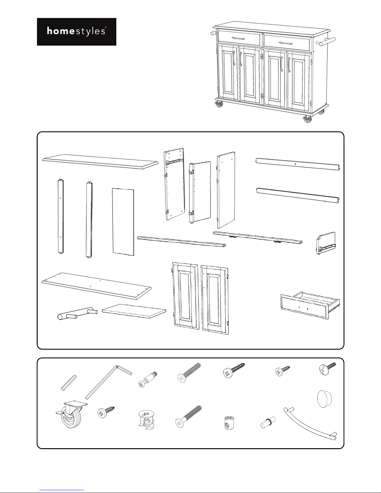
Hardware List
Part List
Home Styles Customer Service: www.homestyles-furniture.com,
servicedesk@homestyles-furniture.com,
888-680-7460, 877-831-0319
Tool(s) required for assembly: Phillips screwdriver
88 4528 95
Kitchen Cart
IMPORTANT
Hex Wrench
1 pc.
Small Hex Wrench
1 pc.
M6x35
Head Cap Bolt (short)
12 pcs. (+1 extra)
M6x50
Head Cap Bolt (long)
7 pcs. (+1 extra)
Refer to later page(s) of these
instructions for drawer assembly.
Carefully remove all the parts from the carton and
place them individually on a soft cloth to prevent
scratches or other damage.
Carefully and strictly follow these assembly instructions
to ensure a completed product as designed.
Do not use power tools above 8 volts to assemble.
Caster
2 Locking
2 Non-Locking
4 pcs.
Cam Lock
6 pcs. (+2 extra)
M4x16
Wood Screw
for Caster
16 pcs. (+1 extra)
Cam Lock Screw
6 pcs. (+1 extra)
Wood Plug
9 pcs. (+1 extra)
Cross Dowel
7 pcs. (+1 extra)
Adjustable Pin
8 pcs. (+1 extra)
M3.5x25
Wood Screw (long)
16 pcs. (+1 extra)
M3.5x16
Wood Screw (short)
12 pcs. (+1 extra)
Pull Handle
6 pcs.
Q.
Drawer
2 pcs.
K.
Divider
1 pc.
P.
Door
2 pcs.
J.
Front Piece
1 pc.
E2.
Back Stretcher
1 pc.
E1.
Back Stretcher
1 pc.
D.
Side Panel
1 pc.
C.
Middle Panel
1 pc.
B.
Side Panel
1 pc.
A.
To p
1 pc.
I.
Front Piece
1 pc.
F.
Back Piece
1 pc.
G.
Back Piece
2 pcs.
H.
Back Panel
4 pcs.
O.
Door
2 pcs.
N.
Shelf
2 pcs.
M.
Side Bar
2 pcs.
L.
Base
1 pc.
M4x25
Machine Screw
12 pcs.
Assembly Instructions 2/6
IMPORTANT
Use a soft cloth between these parts and the floor.
Do not use power tools above 8 volts to assemble.
Do not tighten all the bolts until each part is properly assembled.
Keep Hex Wrench in a safe place as the bolts may need to be tightened up in the future.
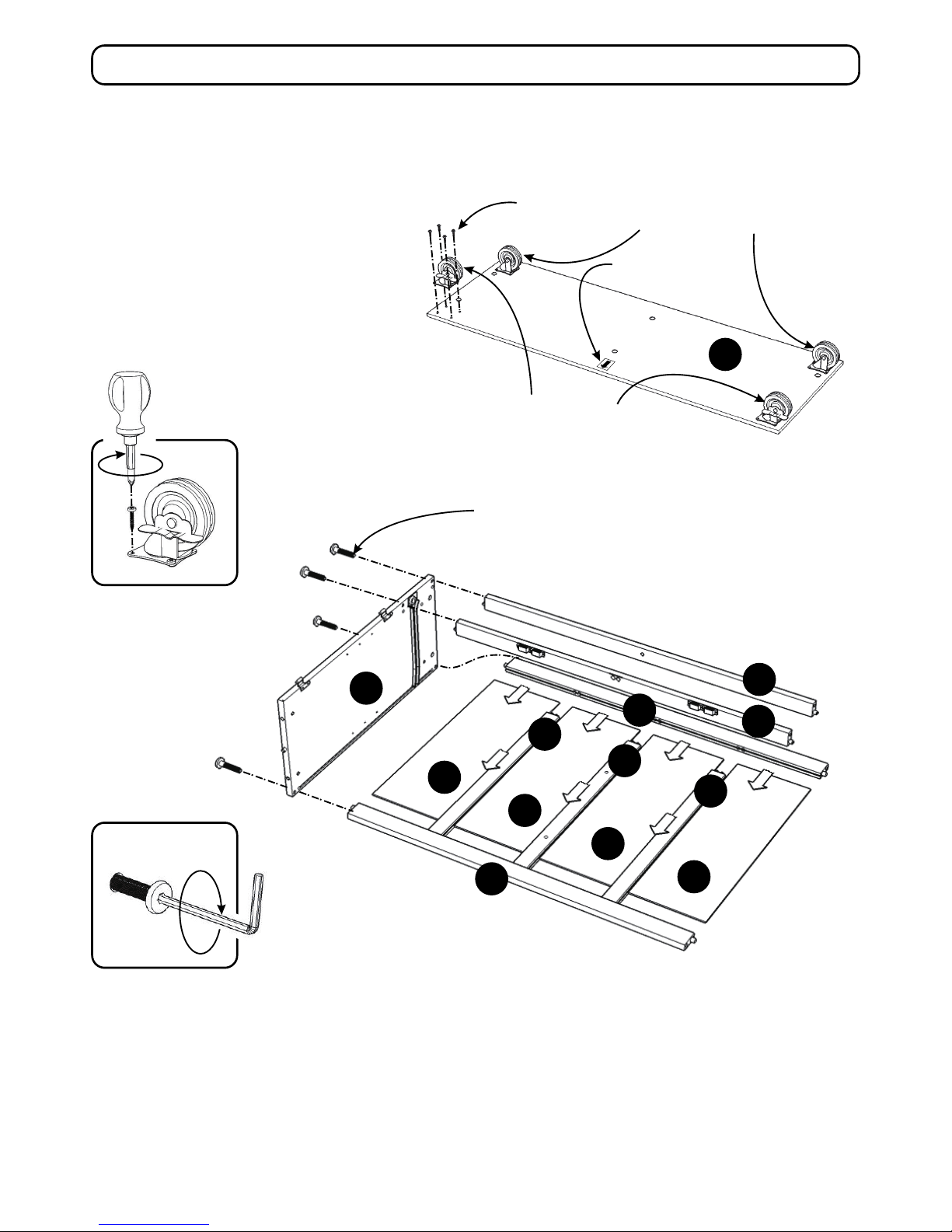
STEP 2
Attach Back Stretcher (E2) to Side Panel (B) with Head Cap Bolt (short). (See Figure 2)
Attach Back Pieces (F) and (G) to Back Stretcher (E2), then slide Back Panels (H) into place.
Attach Back Stretcher (E1) and Front Pieces (I) and (J) to unit with Head Cap Bolts (short).
Figure 2
I
J
B
H
H
H
H
F
G
G
E2
E1
Figure 1
Head Cap Bolt (short)
STEP 1
Attach Casters underneath Base (L) with
Wood Screws for Caster, with Locking
Casters on the front. (See Figure 1)
Note: The ‘Arrow’ sticker indicates
the front of Base (L).
L
Wood Screw for Caster
Locking Caster
Non-Locking Caster
‘Arrow’ sticker at front
Assembly Instructions 3/6
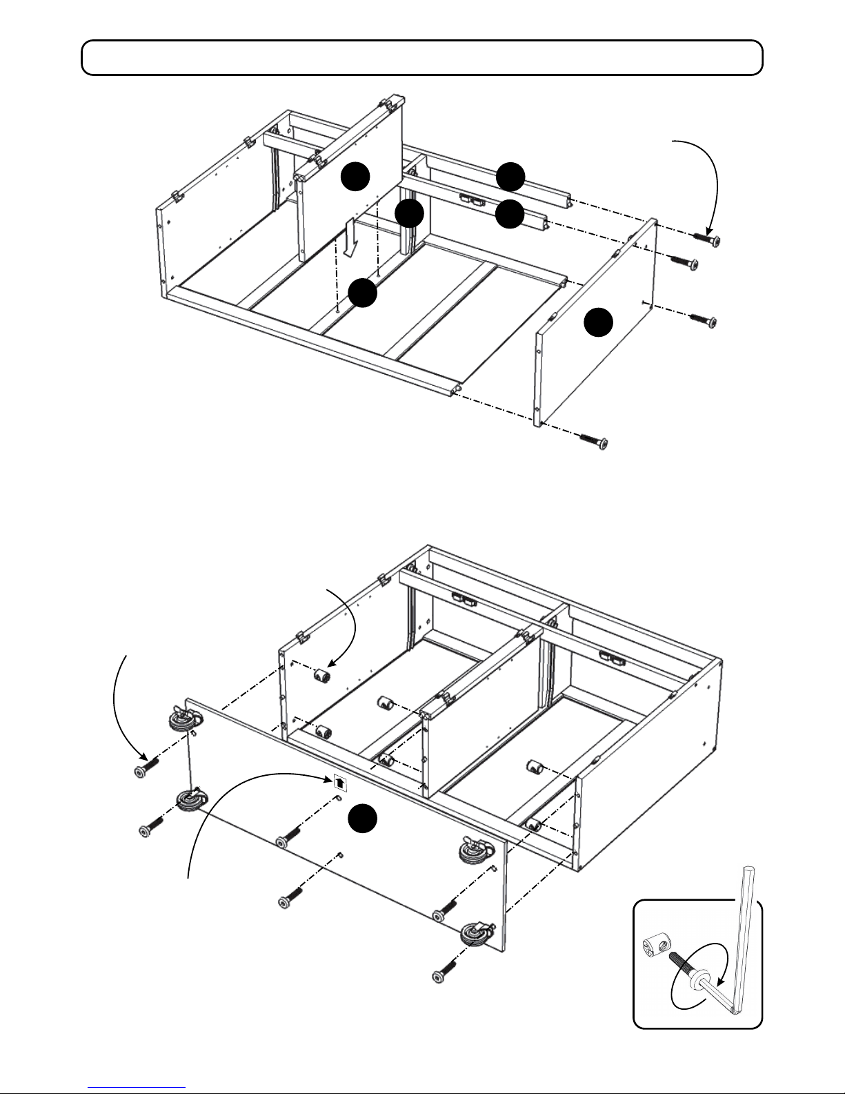
Head Cap Bolt (short)
D
C
I
J
K
F
Figure 3
Cross Dowel
Head Cap Bolt (long)
L
STEP 3
Attach Divider (K) in between Front Pieces (I) and (J).
Attach Middle Panel (C) to Back Piece (F).
Attach Side Panel (D) to the with Head Cap Bolts (short).
STEP 4
Attach Base (L) to unit with Head Cap Bolts (long)
and Cross Dowels. (See Figure 3)
‘Arrow’ sticker at front
 Loading...