

Page 1
88 9100 002C
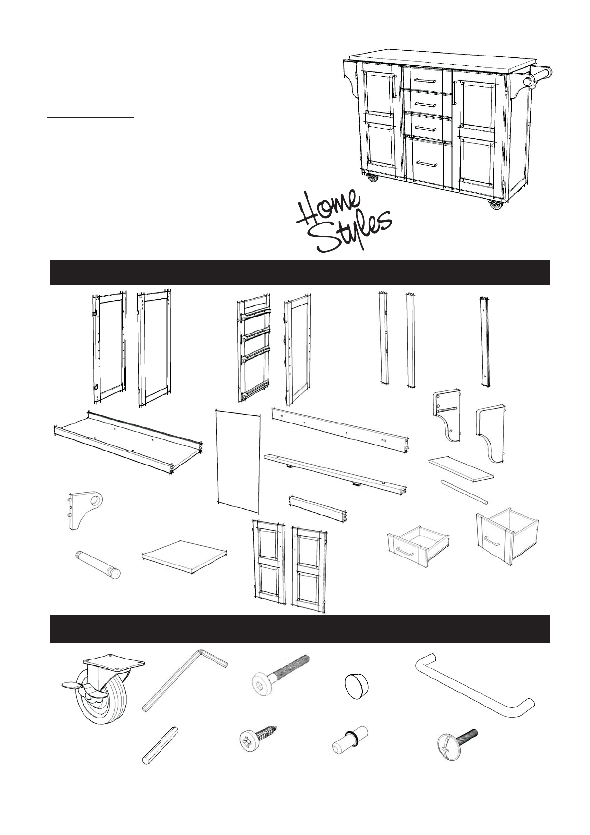
Kitchen Cart (White Finish)
IMPORTANT NOTE
Carefully remove all the parts from the carton and put
them individually on a soft cloth to prevent scratches
or other damages occuring to the wood parts.
We have taken great care in the design of this
product and request that you carefully and strictly
follow our assembly instructions to ensure a
completed product as it was designed.
PART LIST
Side Panel
1 pc.
G.
Base
1 pc.
Q.
Round Arm
1 pc.
A.
P.
Handle Arm
2 pcs.
R.
Shelf
2 pcs.
Middle Panel
B.
Side Panel
1 pc.
Back Panel
3 pcs.
C.
1 pc.
I.
Back Stretcher
1 pc.
H.
Door
1 pc.
J.
Front Stretcher
1 pc.
S.
D.
Middle Panel
1 pc.
Front Piece
K.
Front Rail
3 pcs.
T.
Door
1 pc.
E1.
1 pc.
Side Rack
Brush Chrome Pipes
U.
KD. Drawer
3 pcs.
(For Drawer U&V packed in separate carton
with hardware and assembly instructions.)
E2.
Front Piece
1 pc.
L.
1 pc.
3 pcs.
F.
Back Piece
2 pcs.
M.
Side Rack
1 pc.
N.
Base Rack
O
1 pc.
V.
KD. Drawer
1 pc.
HARDWARE LIST
Hex Wrench
1 pc.
Caster
two lock
two non-lock
4 pcs.
Small
Hex Wrench
1 pc.
Tools Required For Assembly : Phillips screwdriver
Home Styles Consumer Assistance Line 888-680-7460 and 877-831-0319
servicedesk@homestyles-furniture.com
Head Cap Bolt
14 pcs. (+1 extra)
Wood Screw
for Caster
16 pcs. (+2 extra)
Wood Plug
10 pcs.
(+2 extra)
Adjustable Pin
8 pcs. (+2 extra)
Pull Handle
2 pcs.
Machine Screw
for Pull Handle
4 pcs.
Page 2
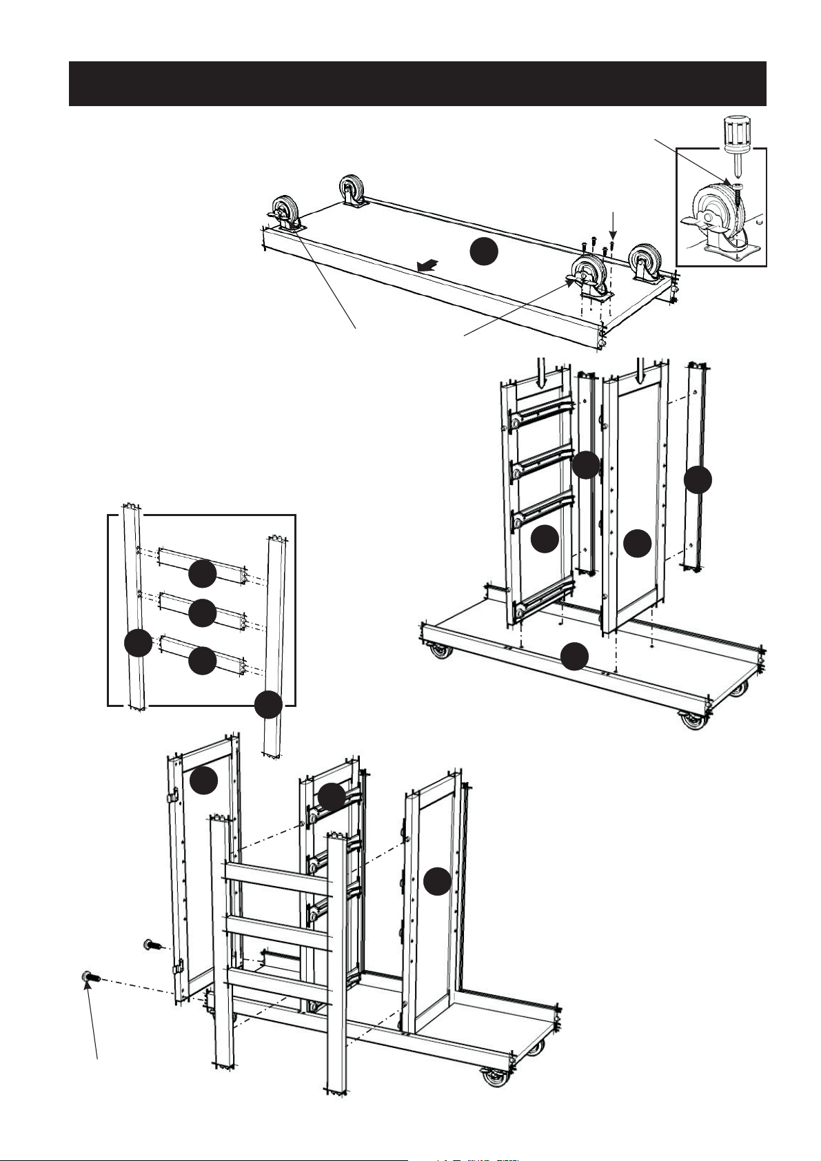
Assembly Instructions 2/3
IMPORTANT
Do not tighten up all the screws until each part is properly assembled.
You should keep Hex Wrench in the safe place as you may need to
tighten up the Head Cap Bolts in the future.
STEP 1
Attach four Casters
underneath Base (G)
with Wood Screws.
(See ‘Arrow’ sticker
indicating front side)
Locking Caster
(On Front)
STEP 2
Attach the Back Piece (F), Middle Panel (C)
and Back Piece (F), Middle Panel (D) onto the
Base (G).
Wood Screw
Wood Screw
G
F
F
E1
(Figure 1)
K
K
K
A
E2
C
D
C
D
G
STEP 3
Assemble Front Piece (E1),
(E2) and Front Rail (K).
(See figure 1)
Attach
to Middle Panel (C) and (D).
Attach Side Panel (A) to
side of unit with Head Cap Bolts.
the assembled unit
the
Head Cap Bolt
Page 3

Assembly Instructions 3/3
STEP 4
Slide Back Panel (H) into place.
Attach Back and Front
Stretcher (I), (J) to the unit
with Head Cap Bolts.
Attach Side Panel (B) to the other
side of unit with Head Cap Bolts.
Head Cap Bolt
L
O
N
M
A
Head Cap Bolt
I
H
H
H
J
B
STEP 5
Attach Side Rack (L) to Side Panel (A) with
Head Cap Bolts.
Attach Brush Chrome Pipes (O) and Base Rack (N)
to the Side Rack (L).
STEP 6
Attach Handle Arm (P) to Side Panel (B)
with Head Cap Bolts.
Slide the Round Arm (Q) into place.
R
R
Attach Side Rack (M) to the Side Panel (A),
using Head Cap Bolts.
B
Head Cap Bolt
P
STEP 7
Insert Adjustable Pins into both
side panels and middle panels
at the desired level.
Place Shelf (R).
P
Q
Adjustable Pin
STEP 8
Cover up all holes
with Wood Plugs.
Page 4

88 9100 002 C
Drawer (U)
UNIT PART LIST
U1.
Front Part
1 pc. for each
drawer.
U2.
Back Part
1 pc. for each
drawer.
U3
(Figure 1)
U2
U3.
Side Part
1 pc. for each
drawer.
U1
U4
make sure roller
is on the back
U4.
Side Part
1 pc. for each
drawer.
U5.
Base Part
1 pc. for each
drawer.
Machine Screw
for Pull Handle
6 pcs.
Assembly
Using a ,philips screwdriver
insert 1 screws into the pre-drilled
holes as shown, tighten half way.
(See the figure 1)
”
U3
HARDWARE LIST
Pull Handle
3 pcs.
Wood Screw (short)
for base part
18 pcs.(+1 extra)
Wood Screw (long)
for side part
24 pcs.(+1 extra)
Instructions
U1
Slide the Plywood Base Part (U5) into
the grooves on Side Parts (U3) and (U4).
Be sure to push the plywood all the way
forward so it meets the Front Part (U1).
(See the figure 2)
U3
U5
U2
U1
U4
(Figure 3)
* If you are missing any of these
parts, please contact our DMI
Customer Service Department
at 1-877-831-0319 or fax us at
1-800-755-2878.
(Figure 2)
Unfinished Side
U5
Insert the remaining (6) 1/2 screws
into the pre-drilled holes on Base Part
(U5), then tighten all screws.
Assemble the Pull Handle
with Machine Screw on
the Front Part (U1).
”
U4
U1
Page 5

88 9100 002 C
Drawer (V)
UNIT PART LIST
V1.
Front Part
1 pc.
V2.
Back Part
1 pc. .
V3
V3.
Side Part
1 pc. .
V1
HARDWARE LIST
Pull Handle
V4.
Side Part
1 pc.
V5.
Base Part
1 pc.
Assembly
Using a ,
insert 1 screws into the pre-drilled
holes as shown, tighten half way.
(See the figure 1)
1 pcs.
Machine Screw
for Pull Handle
2 pcs.
Instructions
philips screwdriver
”
Wood Screw (short)
for base part
6 pcs.(+1 extra)
Wood Screw (long)
for side part
8 pcs.(+1 extra)
V4
V2
(Figure 1)
Slide the Plywood Base Part (V5) into
the grooves on Side Parts (V3) and (V4).
Be sure to push the plywood all the way
forward so it meets the Front Part (V1).
(See the figure 2)
V3
V5
V4
V2
(Figure 3)
* If you are missing any of these parts,
please contact our DMI Customer
Service Department at 1-877-831-0319
or fax us at 1-800-755-2878.
make sure roller
is on the back
V3
(Figure 2)
Unfinished Side
V5
Insert the remaining (6) 1/2 screws
V1
into the pre-drilled holes on Base Part
(V5), then tighten all screws
(See the figure 3)
Assemble the Pull Handle
with Machine Screw on
the Front Part (V1).
(See the figure 4)
V1
V4
”
V1
(Figure 4)
 Loading...