

Page 1
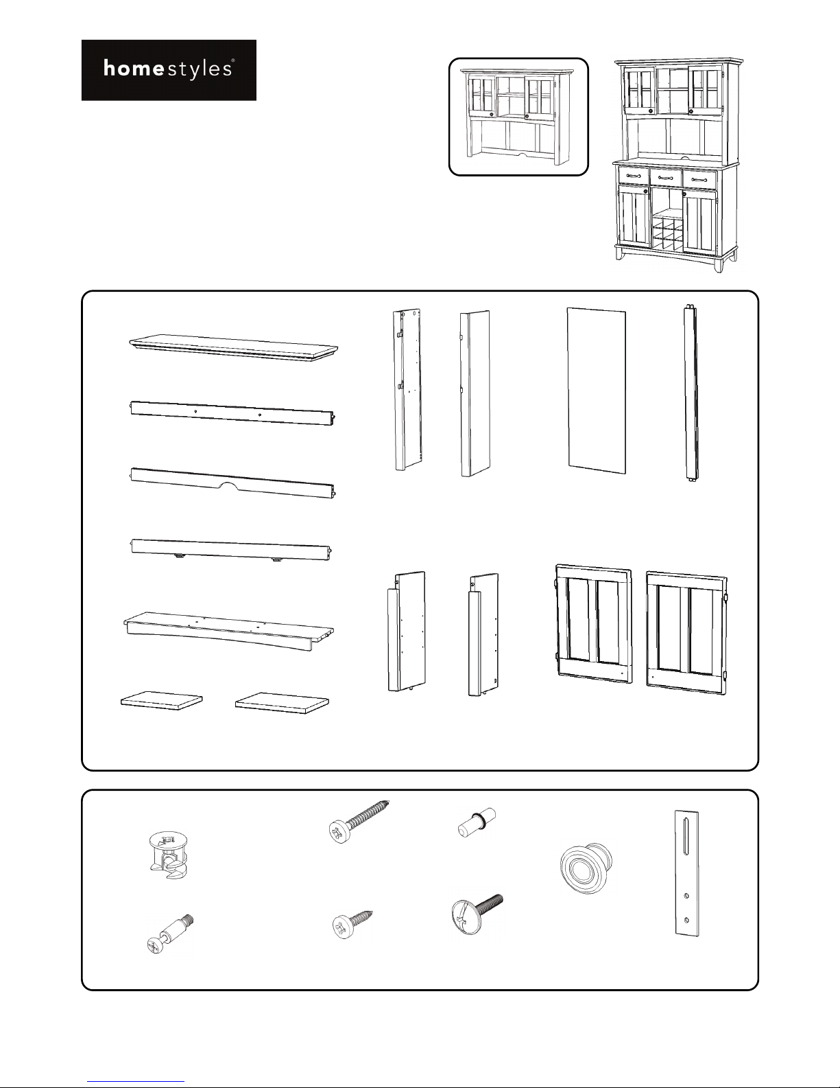
Hardware List
Part List
Home Styles Customer Service: www.homestyles-furniture.com,
servicedesk@homestyles-furniture.com,
888-680-7460, 877-831-0319
Tool(s) required for assembly: Phillips screwdriver, Drill (8 volts or less), 3/8” Drill Bit
88 5100 302
Hutch
IMPORTANT
Carefully remove all the parts from the carton and
place them individually on a soft cloth to prevent
scratches or other damage.
Carefully and strictly follow these assembly instructions
to ensure a completed product as designed.
Do not use power tools above 8 volts to assemble.
A.
To p
1 pc.
Cam Lock
18 pcs. (+2 extra)
Cam Lock Screw
18 pcs. (+1 extra)
M4x13
Wood Screw
for Steel Plate Connector
8 pcs. (+1 extra)
M3.5x16
Wood Screw
for Back Panel
12 pcs. (+1 extra)
Adjustable Pin
12 pcs. (+1 extra)
M4x25
Machine Screw
2 pcs.
Knob
2 pcs.
Steel Plate Connector
2 pcs.
Hutch Unit
F.
Back Stretcher
1 pc.
G.
Back Stretcher
1 pc.
I.
Fixed Shelf
1 pc.
H.
Front Stretcher
1 pc.
J.
Shelf
1 pc.
K.
Shelf
2 pcs.
D.
Back Panel
3 pcs.
E.
Back Upright
2 pcs.
N.
Door
1 pc.
O.
Door
1 pc.
L.
Middle Panel
1 pc.
M.
Middle Panel
1 pc.
B.
Side Panel
1 pc.
C.
Side Panel
1 pc.
Page 2
Assembly Instructions 2/6
IMPORTANT
Use a soft cloth between these parts and the floor.
Do not use power tools above 8 volts to assemble.
Do not tighten all the screws until each part is properly assembled.
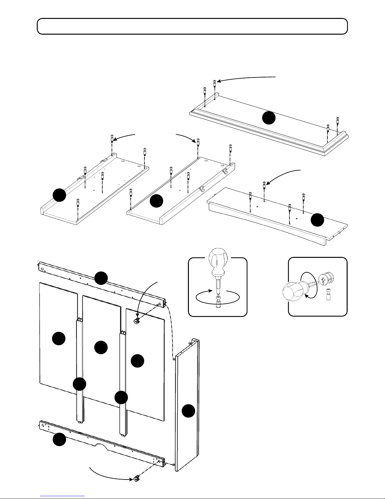
I
B
C
STEP 2
Attach Back Stretcher (G) to Side Panel (B)
with Cam Lock. (See Figure 2)
Attach Back Uprights (E) to Back Stretcher (G),
then slide Back Panels (D) into place.
Attach Back Stretcher (F) to unit with Cam Lock.
Figure 2
F
G
E
E
D
D
D
B
Figure 1
STEP 1
Insert Cam Lock Screws into pre-drilled holes of
Top (A), Side Panels (B), (C) and Fixed Shelf (I).
(See Figure 1)
A
Cam Lock Screw
Cam Lock Screw
Cam Lock Screw
Cam Lock
Cam Lock Screw
Cam Lock
Page 3
Assembly Instructions 3/6
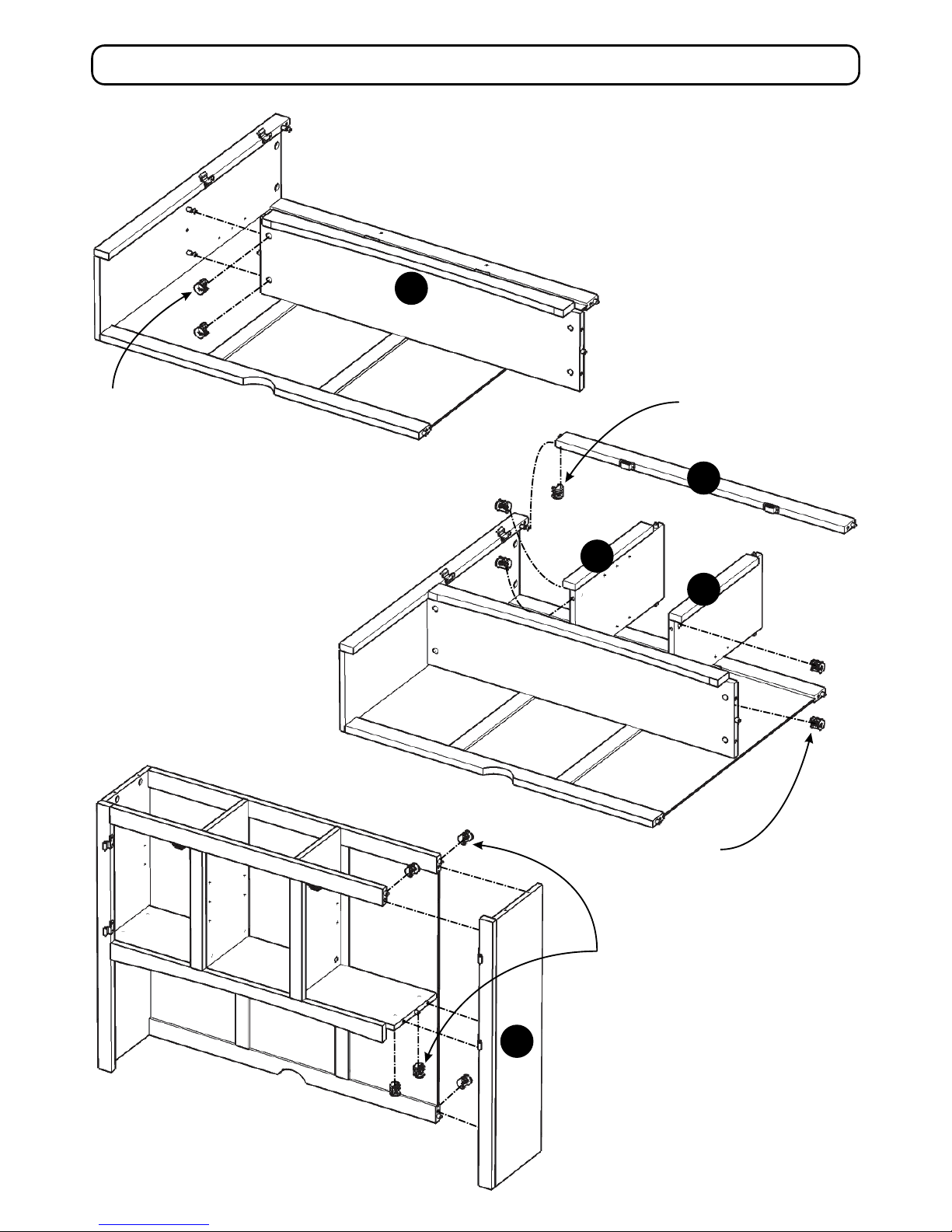
I
M
L
H
Cam Lock
Cam Lock
Cam Lock
C
Cam Lock
STEP 3
Attach Fixed Shelf (I) to unit with Cam Locks.
STEP 4
Attach Middle Panels (L) and
(M) to unit with Cam Locks.
Attach Front Stretcher (H)
to unit with Cam Lock.
STEP 5
Attach Side Panel (C) to unit with
Cam Locks.
Page 4

Assembly Instructions 4/6
Figure 4
Figure 3
STEP 6
Insert Adjustable Pins into
side panels at desired level.
Place Shelves (J) and (K)
into position.
Attach Doors (N) and (O) to unit by
sliding door lift hinges into side panel
lift hinges. (See Figure 3)
Attach Knobs to Doors (N) and (O) with
Machine Screws. (See Figure 4)
K
K
J
N
O
A
STEP 7
Attach Top (A) to unit with Cam Locks.
Adjustable Pin
Cam Lock
Page 5

Assembly Instructions 5/6
STEP 8
Insert Wood Screws for Back Panel
into pre-drilled holes of unit.
STEP 9
Attach Hutch to Buffet with Steel Plate
Connectors by inserting Wood Screws
for Steel Plate Connector into
pre-drilled holes. (See Figure 5)
Wood Screw
for Steel Plate
Connector
Steel Plate
Connector
Wood Screw
for Back Panel
Figure 5
Page 6

Assembly Instructions 6/6
Hardware List
STEP 10
Place unit at desired location.
Drill a 3/8” hole in wall in-line with
pre-drilled hole at top of unit.
Move unit.
Insert Anchor into the wall hole
and attach Bracket with Wall Screw.
Attach Bracket at pre-drilled hole
at top of unit with Wood Screw.
Move unit back into place.
Slide Tip-over Restraint through
Bracket on wall and Bracket on unit.
(See Figure 6)
Put tie end of Tip-over Restraint into lock
end of Tip-over Restraint and pull until tight.
Anchor
1 pc. (+1 extra)
Bracket
2 pcs. (+1 extra)
M3.5x40
Wall Screw
1 pc. (+1 extra)
M3.5x16
Wood Screw
1 pc. (+1 extra)
Figure 6
Wood Screw
Wall Screw
Bracket
on wall
Anchor in wall
3/8” wall hole
Pre-drilled hole
at top of unit
Tie end
Lock end
Bracket at
top of unit
Tip-over
Restraint
IMPORTANT
To help reduce the risk of the unit tipping over, the Tip-over Restraint must be installed following these instructions exactly.
Drill 3/8” hole in wall
Top of unit
Tip-over Restraint
1 pc. (+1 extra)
Page 7

NEVER
use glass cleaners on
finished furniture. Ammonia
chemically attacks the finish.
allow liquids to remain on furniture.
Absorption causes parts to warp
and split and finishes to delaminate.
NEVER
CARE INSTRUCTIONS
Do not use rubber
based placemats.
PREVENT
DISCOLORING
Do not use commercial
waxes and polishes.
PREVENT
YELLOWING
Do not place hot
objects on surface.
PREVENT
FINISH DAMAGE
Do not write
directly on surface.
PREVENT
MARKING
Do not use power tools
above 8 volts to assemble.
PREVENT
CRACKING
Do not place
in direct sunlight.
PREVENT
FADING
with a soft cloth moistened
in lukewarm soap and water.
Buff with a dry clean cloth.
CLEAN
Home Styles will provide replacements free of charge for missing or damaged hardware or parts within 30 days of
purchase. Digital images of the defective parts may be required. If the product was not purchased from an authorized
retail affiliate, Home Styles is underno obligation to provide replacement parts. Parts are not available for fully assembled
items nor are parts available for sale. Replacements for missing or damaged hardware or parts may be requested at:
www.homestyles-furniture.com/customer-service/replacement-parts
Home Styles Customer Service: www.homestyles-furniture.com,
servicedesk@homestyles-furniture.com,
888-680-7460, 877-831-0319
 Loading...