

Page 1
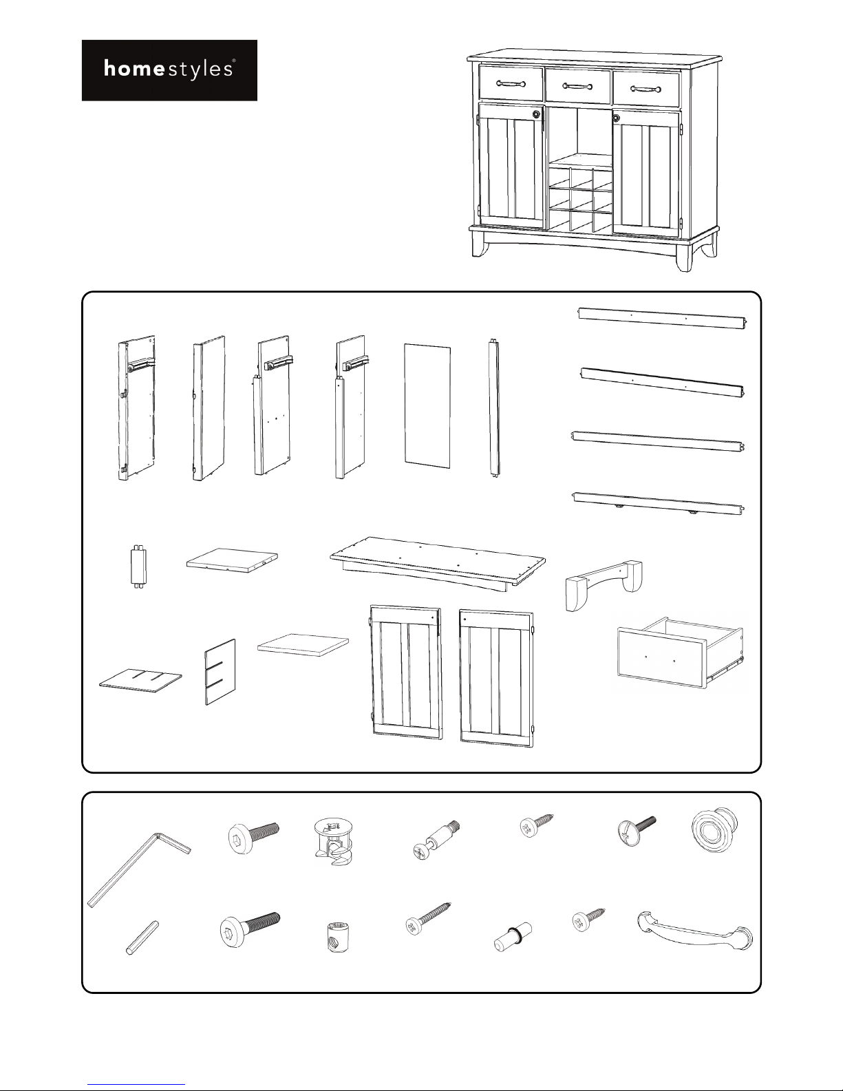
Hardware List
Part List
Home Styles Customer Service: www.homestyles-furniture.com,
servicedesk@homestyles-furniture.com,
888-680-7460, 877-831-0319
Tool(s) required for assembly: Phillips screwdriver, Level, Drill (8 volts or less), 3/8” Drill Bit
88 5100 006
Buffet
IMPORTANT
Refer to later page(s) of these
instructions for drawer assembly.
Carefully remove all the parts from the carton and
place them individually on a soft cloth to prevent
scratches or other damage.
Carefully and strictly follow these assembly instructions
to ensure a completed product as designed.
Do not use power tools above 8 volts to assemble.
A.
Side Panel
1 pc.
B.
Side Panel
1 pc.
E.
Back Panel
3 pcs.
C.
Middle Panel
1 pc.
D.
Middle Panel
1 pc.
F.
Back Upright
2 pcs.
G.
Back Stretcher
1 pc.
H.
Back Stretcher
1 pc.
I.
Front Stretcher
1 pc.
J.
Front Stretcher
1 pc.
K.
Front Upright
2 pcs.
Q.
Shelf
2 pcs.
L.
Fixed Shelf
1 pc.
M.
Base
1 pc.
O.
Wine Grid
2 pcs.
P.
Wine Grid
2 pcs.
Hex Wrench
1 pc.
Small Hex Wrench
1 pc.
M6x35
Head Cap Bolt
4 pcs. (+1 extra)
M6x50
Head Cap Bolt (long)
8 pcs. (+1 extra)
Cam Lock
14 pcs. (+2 extra)
Cross Dowel
8 pcs. (+1 extra)
Cam Lock Screw
14 pcs. (+1 extra)
M3.5x25
Wood Screw (long)
24 pcs. (+1 extra)
M3.5x13
Wood Screw (short)
12 pcs. (+1 extra)
Adjustable Pin
8 pcs. (+2 extra)
M3.5x16
Wood Screw
for Back Panel
12 pcs. (+1 extra)
Pull Handle
3 pcs.
M4x25
Machine Screw
8 pcs.
Knob
2 pcs.
R.
Door
1 pc.
S.
Door
1 pc.
N.
Leg
2 pcs.
T.
Drawer
3 pcs.
Page 2
Assembly Instructions 2/8
IMPORTANT
Use a soft cloth between these parts and the floor.
Do not use power tools above 8 volts to assemble.
Do not tighten all the bolts until each part is properly assembled.
The unit must be level to work properly. Use the included adjustable levelers to level.
Keep Hex Wrench in a safe place as the bolts may need to be tightened up in the future.
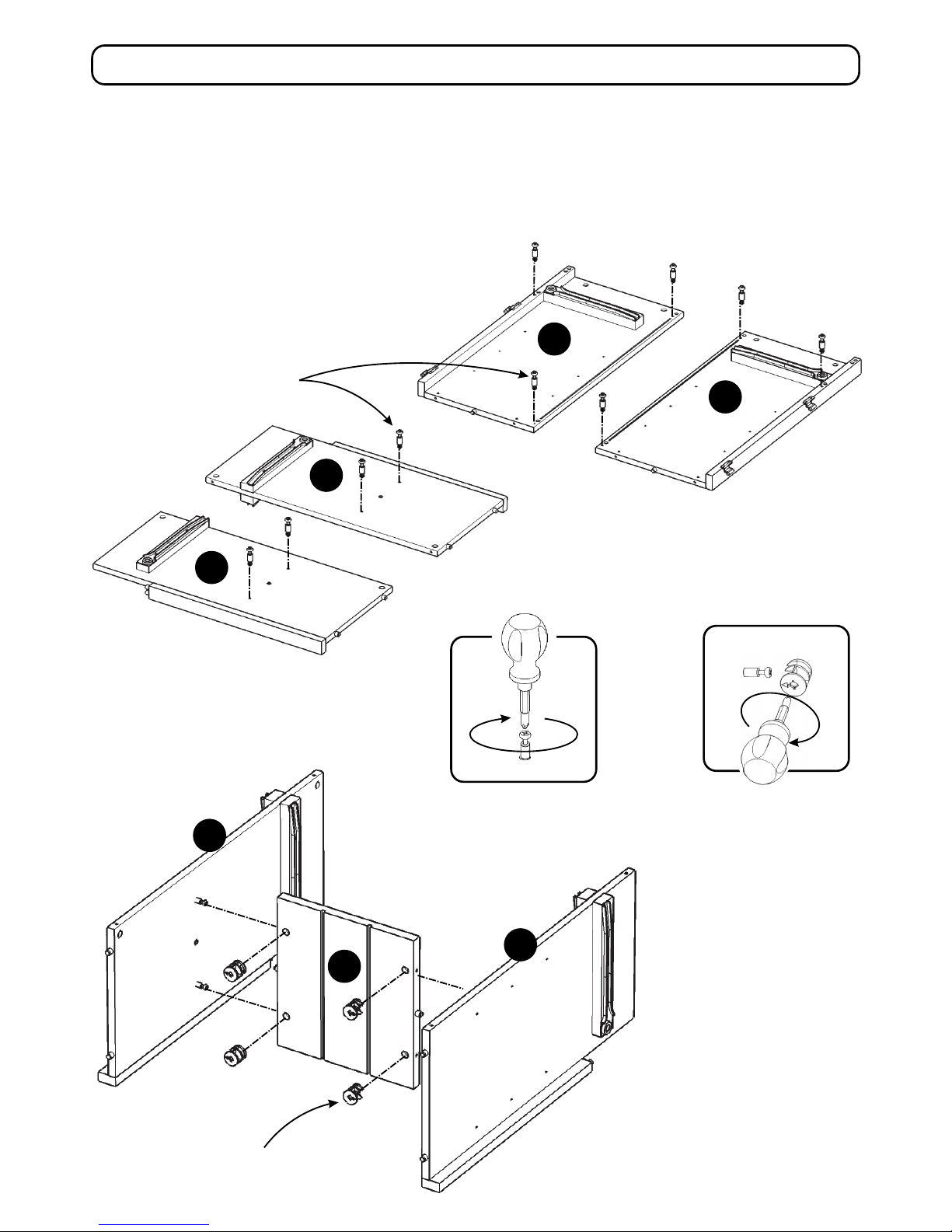
Figure 1
Cam Lock Screw
L
C
D
Cam Lock
STEP 2
Attach Middle Panels (C) and (D)
to Fixed Shelf (L) with Cam Locks.
(See Figure 2)
Figure 2
C
D
A
B
STEP 1
Insert Cam Lock Screws into pre-drilled holes
of Side Panels (A), (B) and Middle Panels (C), (D).
(See Figure 1)
Page 3
Assembly Instructions 3/8
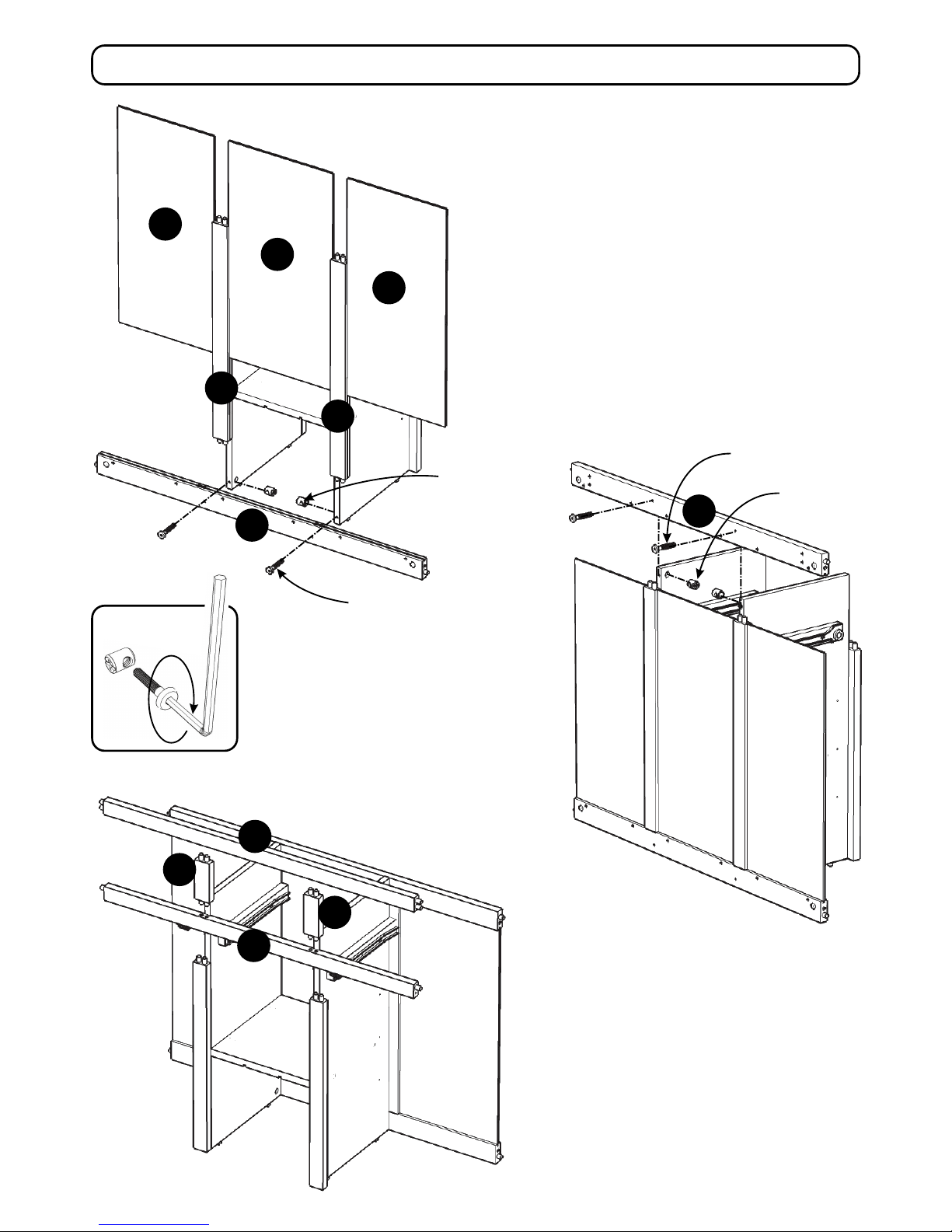
G
H
E
F
Cross Dowel
Head Cap Bolt (long)
STEP 4
Attach Back Stretcher (G) to
unit with Cross Dowels
and Head Cap Bolts (long).
Figure 3
I
K
K
J
E
E
F
STEP 3
Attach Back Stretcher (H) to unit with Cross Dowels
and Head Cap Bolts (long). (See Figure 3)
Attach Back Uprights (F) to Back Stretcher (H).
Slide Back Panels (E) into place.
STEP 5
Attach Front Stretcher (J) to unit.
Attach Front Uprights (K) to unit.
Attach Front Stretcher (I) to unit.
Cross Dowel
Head Cap Bolt (long)
Page 4

Assembly Instructions 4/8
A
B
Cam Lock
STEP 6
Attach Side Panels (A) and (B) to
unit with Cam Locks.
STEP 7
Attach Base (M) to unit with Cross Dowels
and Head Cap Bolts (long).
Attach Legs (N) to Base (M) with Head Cap Bolts.
STEP 8
Insert Cam Lock Screws into pre-drilled holes of Top.
Cam Lock Screw
Head Cap Bolt (long)
Head Cap Bolt
N
M
N
‘Arrow’ sticker at front
Cam Lock
Cross Dowel
Page 5

Assembly Instructions 5/8
STEP 9
Turn unit to its’ upright position.
Insert Adjustable Pins into
side panels and middle panels
at desired level.
Place Shelves (Q) into position.
Attach Doors (R) and (S) to unit by
sliding door lift hinges into
side panel lift hinges.
(See Figure 4)
Attach Knobs to Doors (R) and (S)
with Machine Screws. (See Figure 5)
Figure 4 Figure 5
Q
Q
R
S
Cam Lock
Adjustable Pin
STEP 10
Attach Top to unit with Cam Locks.
Note: ‘Arrow’ sticker indicates front of Top.
Page 6

Assembly Instructions 6/8
STEP 13
Attach Pull Handle with Machine Screws.
STEP 12
Slide Drawer Bottom (T5) into the grooves
of Drawer Sides (T3) and (T4) until it meets
Drawer Front (T1).
Attach Drawer Bottom (T5) to unit with
Wood Screws (short).
T1
T2
T3
T4
T5
T1.
Drawer Front
3 pcs.
T2.
Drawer Back
3 pcs.
T3.
Drawer Side
3 pcs.
T4.
Drawer Side
3 pcs.
T5.
Drawer Bottom
3 pcs.
Drawer (T)
STEP 11
Attach Drawer Front (T1) and Drawer
Back (T2) to Drawer Side (T3) with
Wood Screws (long).
Attach Drawer Side (T4) to unit with
Wood Screws (long).
Pull Handle
T1
T2
T3
T4
Bottom
Roller at back
Wood Screw (long)
Wood Screw (short)
Machine Screw
Part List
Page 7

Assembly Instructions 7/8
T
P
O
O
STEP 14
Slide Drawers (T) into position.
Slide Wine Grids (P) into the
grooves of Fixed Shelf (L).
Slide Wine Grids (O) into unit.
STEP 15
Level unit by adjusting the adjustable
levelers on bottom of unit.
(See Figure 6)
Insert Wood Screws for Back Panel
into pre-drilled holes of back panel.
Note: Unit must be level before
tightening these screws.
Wood Screw for Back Panel
P
T
T
Figure 6
L
Page 8

Assembly Instructions 8/8
Hardware List
STEP 16
Place unit at desired location.
Drill a 3/8” hole in wall in-line with
Pre-drilled hole at top of unit.
Move unit.
Insert Anchor into the wall hole
and attach Bracket with Wall Screw.
Attach Bracket at pre-drilled hole
at top of unit with Wood Screw.
Move unit back into place.
Slide Tip-over Restraint through
Bracket on wall and Bracket on unit.
(See Figure 7)
Put tie end of Tip-over Restraint into lock
end of Tip-over Restraint and pull until tight.
Anchor
1 pc. (+1 extra)
Bracket
2 pcs. (+1 extra)
Tip-over Restraint
1 pc. (+1 extra)
M3.5x40
Wall Screw
1 pc. (+1 extra)
M3.5x16
Wood Screw
1 pc. (+1 extra)
Figure 7
Wood Screw
Wall Screw
Bracket
on wall
Anchor in wall
3/8” wall hole
Pre-drilled hole
at top of unit
Tie end
Lock end
Bracket at
top of unit
Tip-over
Restraint
IMPORTANT
To help reduce the risk of the unit tipping over, the Tip-over Restraint must be installed following these instructions exactly.
Drill 3/8” hole in wall
Top of unit
Page 9

NEVER
use glass cleaners on
finished furniture. Ammonia
chemically attacks the finish.
allow liquids to remain on furniture.
Absorption causes parts to warp
and split and finishes to delaminate.
NEVER
CARE INSTRUCTIONS
Do not use rubber
based placemats.
PREVENT
DISCOLORING
Do not use commercial
waxes and polishes.
PREVENT
YELLOWING
Do not place hot
objects on surface.
PREVENT
FINISH DAMAGE
Do not write
directly on surface.
PREVENT
MARKING
Do not use power tools
above 8 volts to assemble.
PREVENT
CRACKING
Do not place
in direct sunlight.
PREVENT
FADING
with a soft cloth moistened
in lukewarm soap and water.
Buff with a dry clean cloth.
CLEAN
Home Styles will provide replacements free of charge for missing or damaged hardware or parts within 30 days of
purchase. Digital images of the defective parts may be required. If the product was not purchased from an authorized
retail affiliate, Home Stylesis under no obligation to provide replacement parts. Parts arenot available for fullyassembled
items nor are parts available forsale.Replacements for missing or damaged hardware or parts mayberequestedat:
www.homestyles-furniture.com/customer-service/replacement-parts
Home Styles Customer Service: www.homestyles-furniture.com,
servicedesk@homestyles-furniture.com,
888-680-7460, 877-831-0319
 Loading...