

Page 1
IMPORTANT NOTE
Carefully remove all the parts from the carton and put
them individually on a soft cloth to prevent scratches
or other damages occuring to the parts.
We have taken great care in the design of this
product and request that you carefully and strictly
follow our assembly instructions to ensure a
completed product as it was designed.
Tools required for assembly : Phillipsscrewdriver
Home Styles Consumer Assistance Line 888-680-7460 and 877-831-0319
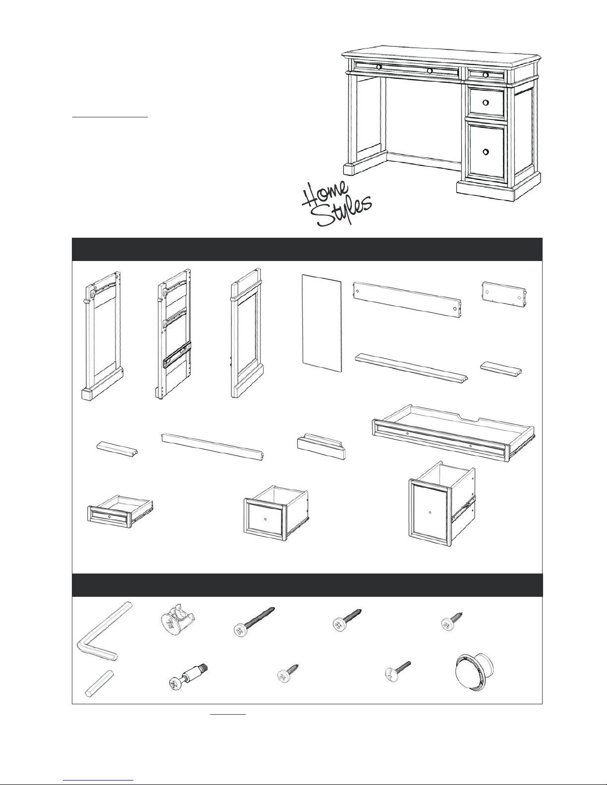
Hardware List
88 5002 79
Tools recommended for assembly :
Level
Part List
Traditions
Kitchen Desk
B.
Middle Panel
1 pc.
C.
Side Panel
1 pc.
G.
Front Rail
1 pc.
A.
Side Panel
1 pc.
D.
Back Panel
1 pc.
O.
Drawer
1 pc.
E.
Back Rail
1 pc.
K.
Plinth
1 pc.
F.
Back Rail
2 pcs.
H.
Front Rail
1 pc.
I.
Front Rail
1 pc.
J.
Stretcher
1 pc.
L.
Keyboard Box
1 pc.
M.
Drawer
1 pc.
N.
Drawer
1 pc.
( Drawer (M), (N) and (O) Knock-Down construction, please refer to the last page of these instructions for drawer assembly step )
Cam Lock Screw
18 pcs.(+1 extra)
Cam Lock
18 pcs.
(+1 extra)
Small
Hex Wrench
1 pc.
Wood Screw (short)
for Back Panel
4 pcs. (+1 extra)
Wood Screw
for Stretcher
2 pcs. (+1 extra)
Hex Wrench
1 pc.
Wood Screw (long)
for Drawer Side Part
28 pcs. (+1 extra)
Pull Handle
5 pcs.
Machine
Screw
5 pcs.
Wood Screw (short)
for Drawer Base Part
12 pcs. (+1 extra)
Page 2
Assembly Instructions 2/7
IMPORTANT
B
C
Figure 1
Figure 2
F
F
H
I
K
D
Cam Lock
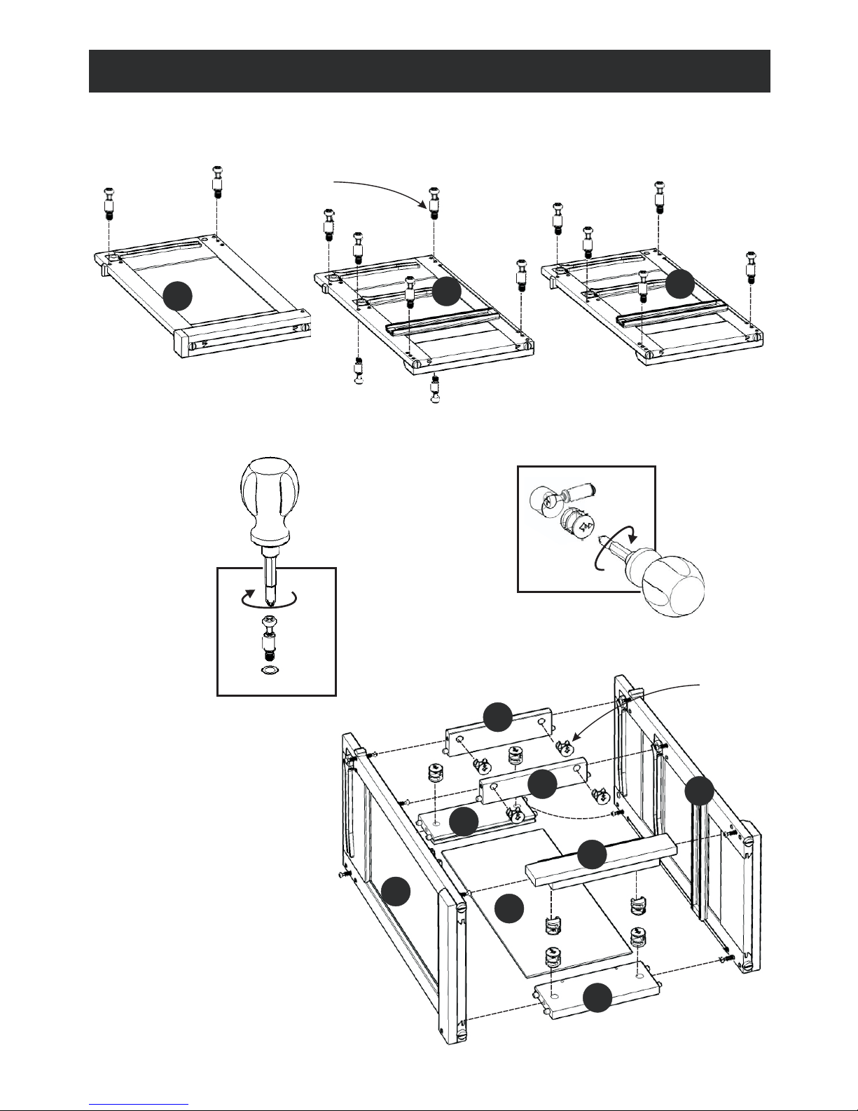
Step 1
Put Cam Lock Screws into the pre-drilled holes of Side Panel (A), (C) and Middle Panel (B) and
tighten. (see Figure 1)
* Do not tighten up all the screws until each part is properly assembled.
* You should keep Hex Wrench and in a safe place as you may need to tighten up the Cam Locks in the future.
Step 2
Attach Back Rails (F) to
Side Panel (C) with Cam Locks.
(see Figure 2)
Slide Back Panel (D) into unit.
Attach Front Rail (H), (I) and
Plinth (K) to unit with Cam Locks.
Attach Side Panel (B) to unit with
Cam Locks.
C
Cam Lock Screw
* After assembly item must be level to work properly. Use the included adjustable levelers to level.
A
B
Page 3
Assembly Instructions 3/4Assembly Instructions 3/7
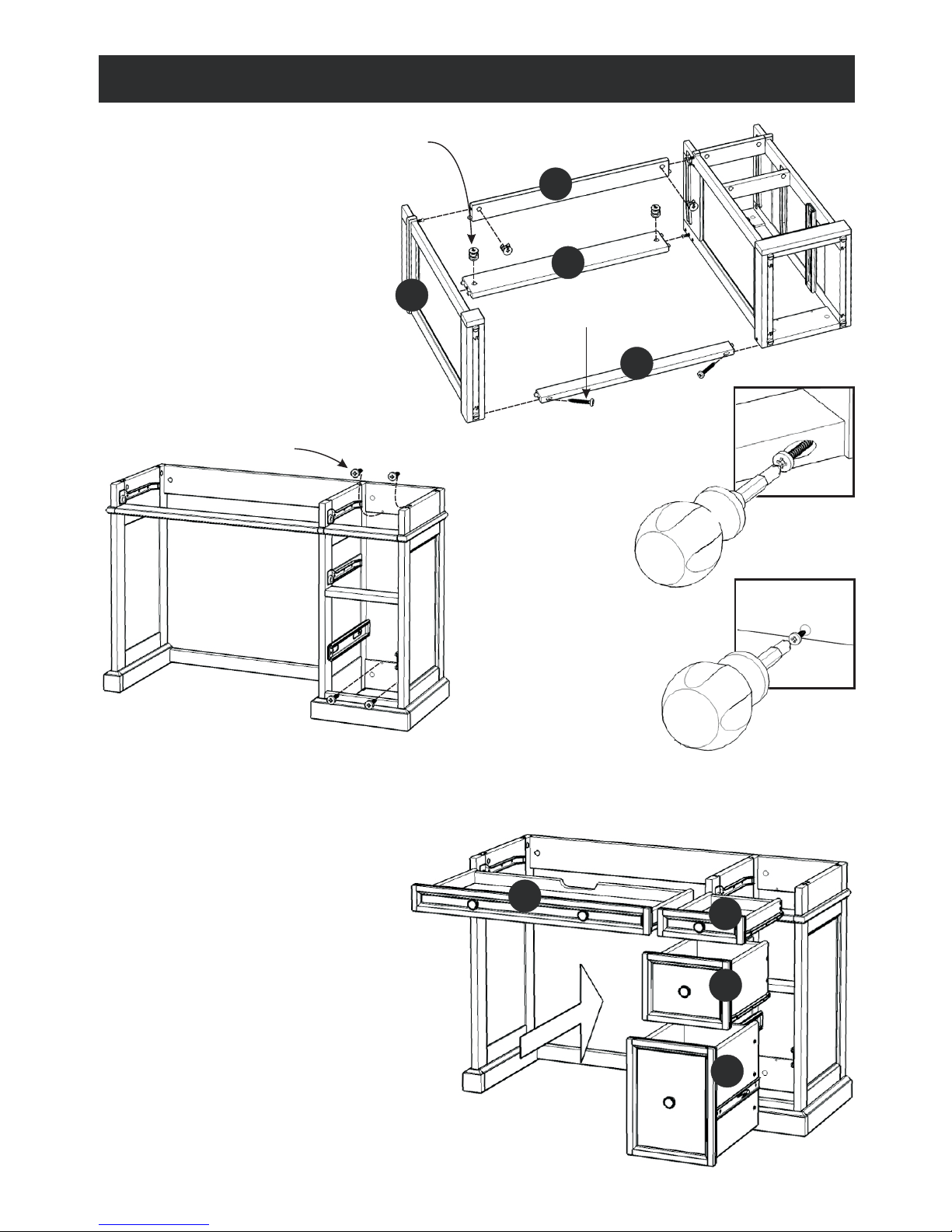
Step 4
Insert 4x Wood Screws for Back Panel into the back of unit, tighten up all the Screws.
(see Figure 4)
E
G
J
A
Wood Screw for Back Panel
Cam Lock
Wood Screw for Stretcher
Step 3
Attach Back Rail (E) and Front
Rail (G) to unit with Cam Locks.
(see Figure 2)
Attach Stretcher (J) to unit with
Wood Screws for Stretcher.
(see Figure 3)
Attach Side Panel (A) to unit with
Cam Locks and Wood Screw for
Stretcher.
Step 5
Slide Drawer (O), (N), (M) and Keyboard Box (L) into position.
L
M
N
O
Figure 4
Figure 3
Page 4
Cam Lock Screw
Assembly Instructions 3/4Assembly Instructions 4/7
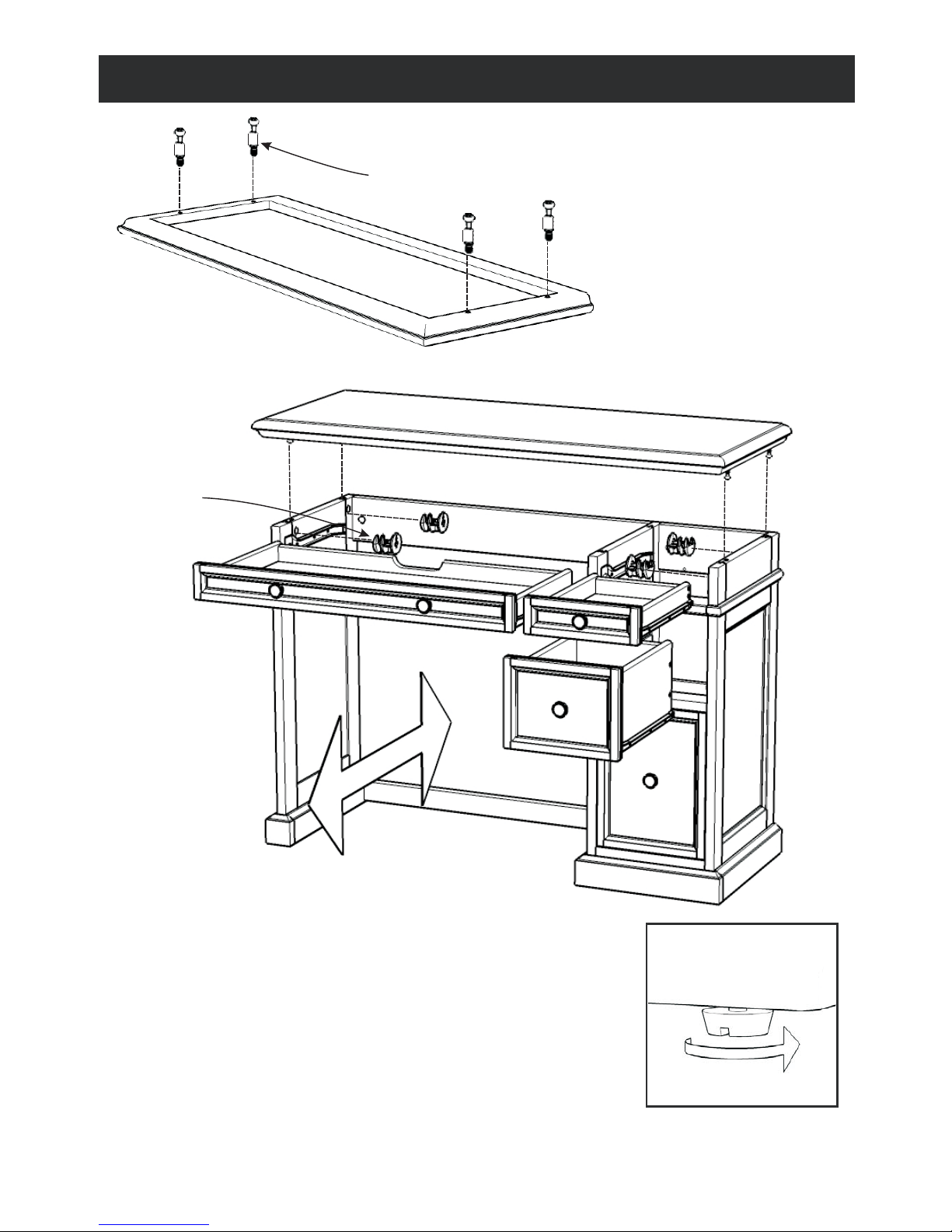
Step 7
Pull out the Drawers from unit.
Place Top onto the unit, using Cam Locks. (see figure 2)
Slide Drawers into place.
To level the unit, adjust the
adjustable levelers on the
bottom of legs.
To level the unit, adjust the
adjustable levelers on the
bottom of legs.
Step 6
Using the Top option that you have
chosen, put the Cam Lock Screws
into the pre-drilled holes of the Top.
(see Figure 1)
Cam Lock
Page 5

Assembly Instructions 5/7
Figure 1
Figure 2
MAKE SURE ROLLER
IS ON THE BACK
M2
M2
M2
M3
M3
M3
M4
M4
M4
M5
M5
M1
M1
M1
Part List
M1.
Front Part
1 pc.
M5.
Base Part
1 pc.
M2.
Back Part
1 pc.
M3.
Side Part
1 pc.
M4.
Side Part
1 pc.
Attach M1 to M3 and M4, using
a Phillips screwdriver and
long wood screws (4X),
tighten halfway.
Attach M2 to M3 and M4 using
long wood screws (4X),
tighten halfway. (see Figure 1)
Insert short wood screws (4X)
into the pre-drilled holes in M5,
tighten screws. (see Figure 3)
Slide M5 into the grooves in M3
and M4. Be sure to push M5 all
the way forward so it meets M1.
(see Figure 2)
STEP 1
STEP 2
STEP 3
Tighten all screws used in
drawer assembly.
Figure 4
Attach hardware pulls with
machine screws.
(see Figure 4)
STEP 4
Figure 3
Drawer (M)
Page 6

Assembly Instructions 6/7
Figure 1
Figure 2
MAKE SURE ROLLER
IS ON THE BACK
N2
N2
N2
N3
N3
N3
N4
N4
N4
N5
N5
N1
N1
N1
Part List
N1.
Front Part
1 pc.
N5.
Base Part
1 pc.
N2.
Back Part
1 pc.
M3.
Side Part
1 pc.
N4.
Side Part
1 pc.
Attach N1 to N3 and N4, using
a Phillips screwdriver and
long wood screws (4X),
tighten halfway.
Attach N2 to N3 and N4 using
long wood screws (4X),
tighten halfway. (see Figure 1)
Insert short wood screws (4X)
into the pre-drilled holes in N5,
tighten screws. (see Figure 3)
Slide N5 into the grooves in N3
and N4. Be sure to push N5 all
the way forward so it meets N1.
(see Figure 2)
STEP 1
STEP 2
STEP 3
Tighten all screws used in
drawer assembly.
Figure 4
Attach hardware pulls with
machine screws.
(see Figure 4)
STEP 4
Figure 3
Drawer (N)
Page 7

Assembly Instructions 7/7
Figure 1
Figure 2
O2
O2
O2
O3
O3
O3
O4
O4
O4
O5
O5
O1
O1
O1
Drawer (O)
Part List
O1.
Front Part
1 pc.
O5.
Base Part
1 pc.
O2.
Back Part
1 pc.
O3.
Side Part
1 pc.
O4.
Side Part
1 pc.
Attach O1 to O3 and O4, using
a Phillips screwdriver and
long wood screws (6X),
tighten halfway.
Attach O2 to O3 and O4 using
long wood screws (6X),
tighten halfway. (see Figure 1)
Insert short wood screws (4X)
into the pre-drilled holes in O5,
tighten screws. (see Figure 3)
Slide O5 into the grooves in O3
and O4. Be sure to push O5 all
the way forward so it meets O1.
(see Figure 2)
STEP 1
STEP 2
STEP 3
Tighten all screws used in
drawer assembly.
Figure 4
Attach hardware pulls with
machine screws.
(see Figure 4)
STEP 4
Figure 3
 Loading...