

Page 1
88 5542 942
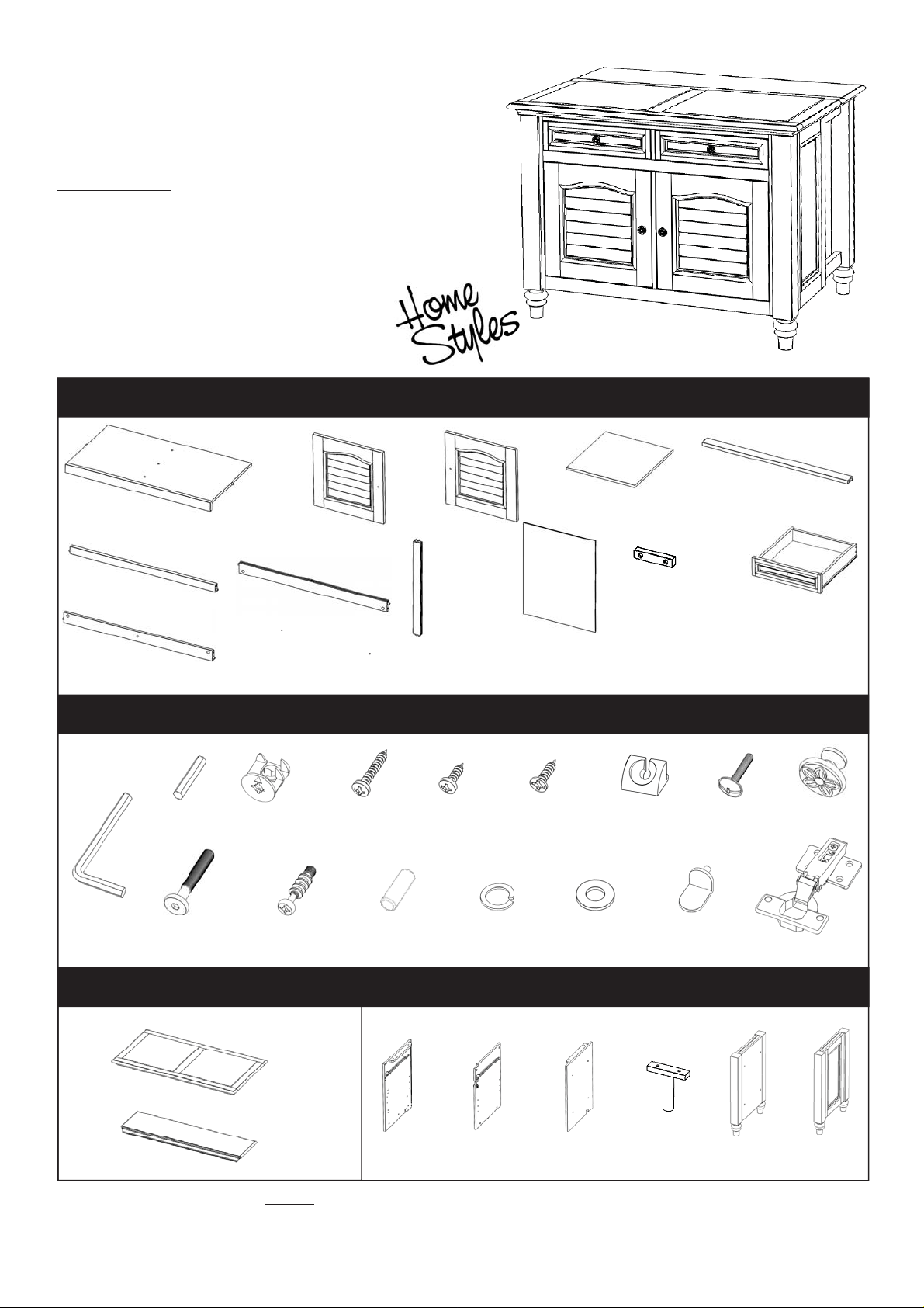
Bermuda
Kitchen Island
IMPORTANT NOTE
Carefully remove all the parts from the carton and put
them individually on a soft cloth to prevent scratches
or other damages occuring to the wood parts.
We have taken great care in the design of this
product and request that you carefully and strictly
follow our assembly instructions to ensure a
completed product as it was designed.
Part List
Patent 8,584,600 B2
B.
Bottom
1 pc.
J.
Front Rail
1 pc.
K.
Back Rail
1 pc.
Hardware List
Small
Hex Wrench
1 pc.
L.
Back Rail
1 pc.
Cam Lock
19 pcs. (+4 extra)
F.
Door
1 pc.
Wood Screw
(long)
16 pc. (+1 extra)
G.
Door
1 pc.
M.
Back Piece
1 pc.
Wood Screw
(short)
12 pcs. (+1 extra)
H.
Shelf
2 pcs.
N.
Back Panel
2 pcs.
Flat Head
Wood Screw
40 pcs. (+2 extra)
P.
Wood Support
1 pc.
Plastic Insert
4 pcs. (+1 extra)
I.
Front Rail
1 pc.
Q.
Drawer
2 pcs.
(Knock-Down Construction
refer of the last page
of instruction for steps to
complete drawer assembly)
Machine Screw
4 pcs.
Pull Handle
4 pcs.
Hex Wrench
1 pc.
Head Cap Bolt
18 pcs. (+1 extra)
Cam Lock Screw
19 pcs. (+1 extra)
Wood Dowel
2 pcs. (+1 extra)
Spring Washer
18 pcs. (+1 extra)
Flat Washer
18 pcs. (+1 extra)
Adjustable Pin
8 pcs. (+1 extra)
Hinge
4 pcs.
For assembly also need the following : 88 5542 941, 88 5542 943
88 5542 941 Bermuda Kitchen Island Carton quatity: 1
A1.
Top
1 pc.
A2.
Leaf Top
1 pc.
Tools required for assembly : Phillips screwdriver Tools recommended for assembly : Leve
Home Styles Consumer Assistance: www.homestyles-furniture.com,
servicedesk@homestyles-furniture.com, 888-680-7460, 877-831-0319
88 5542 943 Bermuda Kitchen Island Carton quatity: 1
O.
C.
Side Panel
1 pc.
D.
Middle Panel
1 pc.
E.
Side Panel
1 pc.
Post
2 pcs.
R.
Side Frame
1 pc.
S.
Side Frame
1 pc.
l
Page 2
Assembly Instruction 2 / 8
C
c
IMPORTANT
* Do not tighten up all the screws until each part is properly assembled.
* You should keep Hex Wrench in a safe place as you may need to tighten up the Head Cap Bolts in the future.
* Use a soft cloth between these parts and the fl oor.
* After assembly, item must be level to work properly. Use the included adjustable levelers to level.
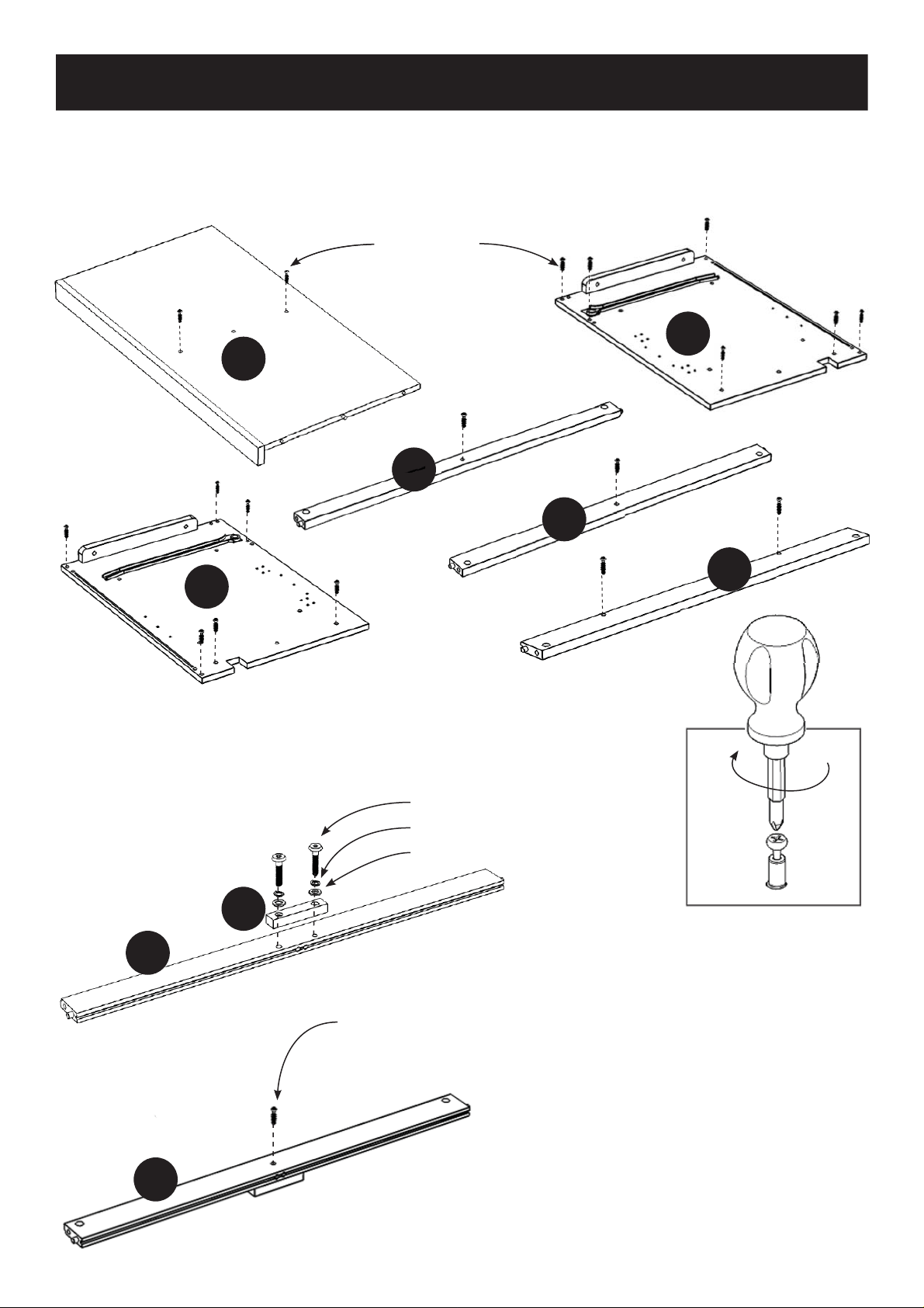
Cam Lock Screw
am Lo
C
B
B
I
J
E
STEP 1
Insert Cam Lock Screws into the pre-drilled holes of Bottom (B), Side
Panel (C), (E), Front Rail (I), (J) and Back Rail (L). (see Figure 1)
Head Cap Bolt
Spring Washer
Flat Washer
P
K
Cam Lock Screw
L
Figure 1
STEP 2
Attach Wood Support (P) to the Back Rail (K)
with Flat Washers, Spring Washers and Head
Cap Bolts.
K
Insert Cam Lock Screw into the pre-drilled
holes of Back Rail (K).
Page 3
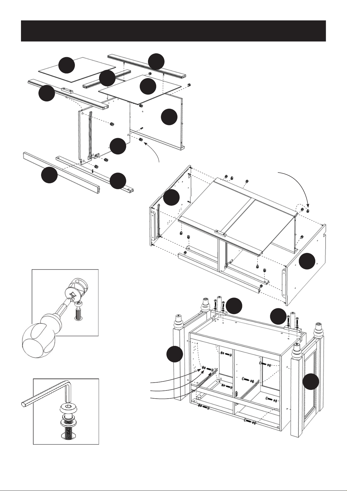
K
N
M
D
N
L
B
Assembly Instruction 3 / 8
STEP 3
Attach Front Rail (I), (J), Bottom (B) and
Back Rail (K) to Middle Panel (D) using
Cam Locks. (see Figure 2)
Attach Back Piece (M) and Back Rail (L)
to unit using Cam Locks.
Slide Back Panel (N) into the grooves in
Back Rail (K), (L) and Back Piece (M).
I
J
STEP 4
Attach Side Panel (C) and (E) to unit
using Cam Locks.
Cam Lock
Cam Lock
E
C
O
O
Figure 2
Figure 3
S
Flat Washer
Spring Washer
Head Cap Bolt
STEP 5
Attach Side Frame (R), (S) and Posts (O) to unit
with Flat Washers, Spring Washers and Head
Cap Bolts. (see Figure 3)
R
Page 4

Assembly Instruction 4 / 8
Figu
STEP 6
Turn the unit over to its’ upright position.
To level the unit, adjust the adjustable levelers on the
stationary frame legs and the posts.
Note : Unit must be level to work properly.
Figure 4
re 4
Flat Head Wood Screw
Plastic Insert
STEP 7
Attach Plastic Inserts to unit with Flat Head Wood Screws. (see Figure 4)
Note : Please make sure unit is level before attaching these plastic inserts.
Page 5

Machine Screw
Assembly Instruction 5 / 8
Flat Head Wood Screw
Hinge
F
G
Pull Handle
STEP 8
Attach Hinges, Pull Handles to Doors (F), (G) with Flat Head Wood Screws and Machine Screws
into the pre-drilled holes. (see Figure 5), (see Figure 6)
Figure 5
Figure 6
Flat Head Wood Screw
A2
A1
STEP 9
Attach Top (A1) to Leaf Top (A2) with Wood Screws for Hinges into the pre-drilled holes.
(see Figure 7)
Figure 7
Page 6

Assembly Instruction 6 / 8
8
Wood Dowel
Flat Washer
Spring Washer
Head Cap Bolt
Wood Screw for Hinge
Adjustable Pin
Wood Dowel
Q
Q
F
G
H
H
STEP 10
Insert Wood Dowels into the unit.
Place top unit onto unit and attach with Flat Washers, Spring Washers and Head Cap Bolts.
(see Figure 8)
Attach Door (F), (G) to unit with Wood Screws for Hinge into the pre-drilled holes. (see Figure 9)
Insert Adjustable Pins into the pre-drilled holes in the side panels and middle panel at the desired
level.
Place Shelf (H) into position.
Slide Drawer (Q) into position.
Figure 8
igure
Figure 9
Page 7

Assembly Instruction 7 / 8
TOP EXTENSION INSTRUCTIONS
STEP 1
Lift up the Leaf Top.
STEP 2
Holding the Leaf Top up, pull out a back leg from
the unit; then pull out the other back leg.
Note : Unit must be level in order for the back legs to be pulled out.
Page 8

Drawer (Q)
4
Q5
.
Q3
Assembly Instruction 8 / 8
Q1
Figure 1
Q2
STEP 1
Attach Q1 to Q2 and Q4, using
a Phillips screwdriver and
long wood screws (4X), tighten
halfway.
Attach Q2 to Q3 and Q4 using
long wood screws (4X), tighten
halfway. (see Figure 1)
Q3
Q1
Q5
Q4
MAKE SURE ROLLER
IS ON THE BACK
Figure 2
Figure 4
Q3
Q5
5
Q1
Q4
STEP 2
Slide Q5 into the grooves in Q3
and Q4. Be sure to push Q5 all
the way forward so it meets Q1.
(see Figure 2)
Q2
STEP 3
Insert short wood screws (6X)
into the pre-drilled holes in Q5
and tighten. (see Figure 3)
Part List
Q1.
Front Part
2 pcs.
Q2.
Back Part
2 pcs.
Q4
Figure 3
STEP 4
Assemble Pull Handle with
machine screws. (see Figure 4)
Tighten all screws used in drawer assembly.
Q3.
Side Part
2 pcs .
Q4
Side Part
2 pcs.
Q5.
Base Part
2 pcs.
Page 9

VERY IMPORTANT !!
CAR INSTRUCTIONSE
NEVER
USE GLASS CLEANERS ON
FINISHED FURNITURE. AMMONIA
WILL CHEMICALLY ATTACK THE
LACQUER.
DO NOT
WRITE
DIRECTLY
ON
SURFACE.
PREVENT
MARKING
DO NOT USE
COMMERCIAL
WAXES AND
POLISHES.
DO NOT
PLACE HOT
OBJECTS
ON SURFACE.
NEVER
ALLOW LIQUIDS OF ANY KIND TO
REMAIN ON THE FURNITURE.
ABSORPTION CAUSES WOOD TO WARP
AND FINISHES TO DELAMINATE.AND SPLIT
DO NOT
PLACE IN
DIRECT
SUNLIGHT.
PREVENT
FADING
DO NOT
USE
RUBBER
BASED
PLACE MATS.
PREVENT
YELLOWING
PREVENT
FINISH DAMAGE
PREVENT
DISCOLORING
TO CLEAN
USE A SOFT CLOTH MOISTENED IN LEMON OIL
POLISH OR LUKEWARM SOAP AND WATER,
THEN BUFF WITH A DRY CLEAN CLOTH.
Home Styles will provide replacements free of charge for missing or damaged hardware or parts within 30 days of purchase.
Digital images of the defective parts may be required. If this product was not purchased from an authorized retail affiliate,
Home Styles is under no obligation to provide replacement parts. Parts are not available for fully assembled items nor are
parts available for sale. Replacements for missing or damaged hardware or parts may be requested at:
www.homestyles-furniture.com/customer_service
Home Styles Consumer Assistance: www.homestyles-furniture.com,
servicedesk@homestyles-furniture.com, 888-680-7460, 877-831-0319
 Loading...