

Page 1
88 5542 09
Bermuda
Entertainment Console
IMPORTANT NOTE
Carefully remove all the parts from the carton and put
them individually on a soft cloth to prevent scratches
or other damages occuring to the parts.
We have taken great care in the design of this
product and request that you carefully and strictly
follow our assembly instructions to ensure a
completed product as it was designed.
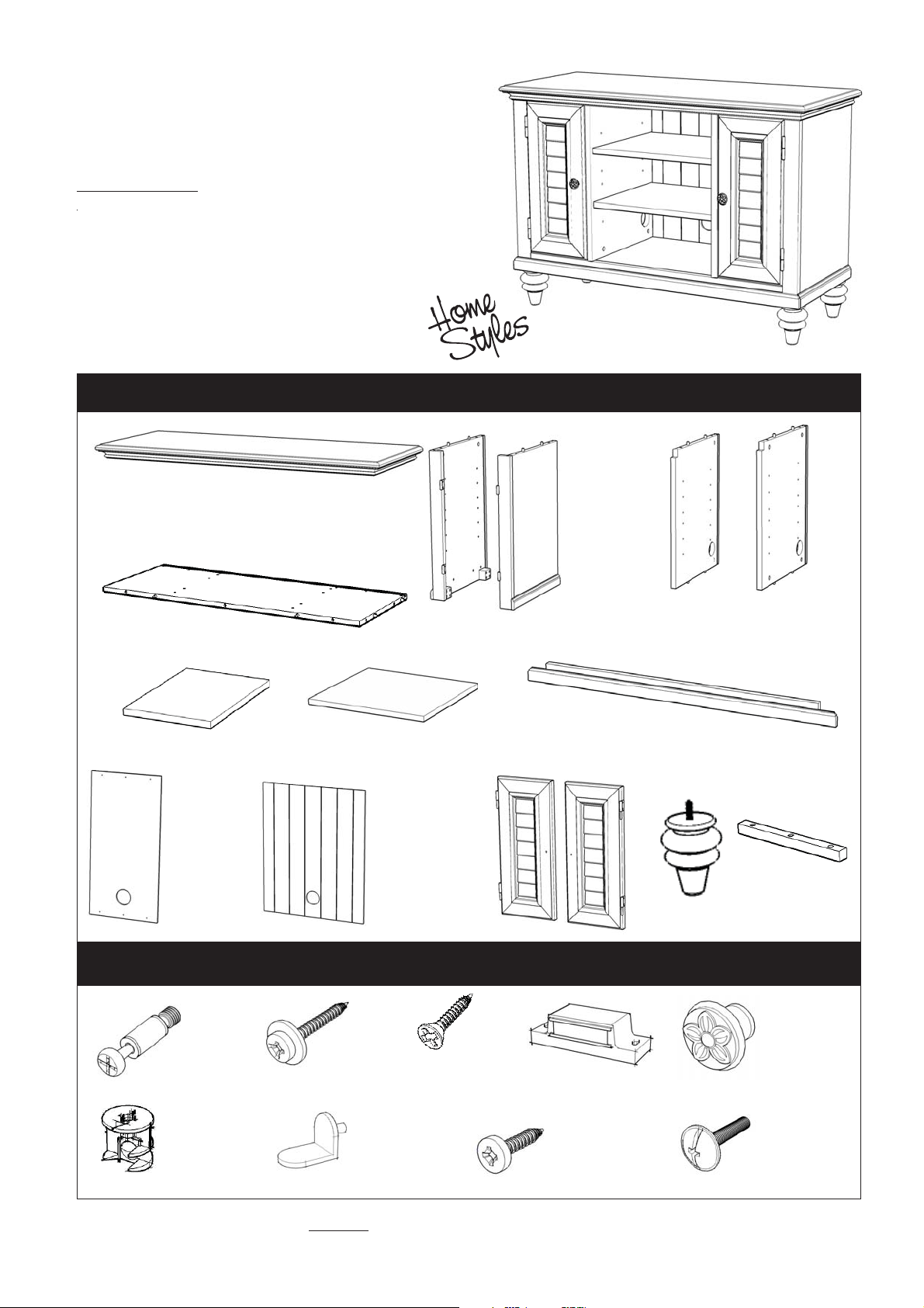
Part List
A.
Top
1 pc.
E.
Base
1 pc.
4 pcs.
I.
Back Panel
2 pcs.
Shelf
B.
Side Panel
.1 pc
F.
J.
Back Panel
1 pc.
G.
Shelf
2 pcs.
K.
Door
1 pc.
C.
Side Panel
1 pc.
Middle Panel
H.
Plinth
1 pc.
L.
Door
1 pc.
D1.
.1 pc
M.
Leg
4 pcs.
D2.
Middle Panel
.1 pc
N.
Wood Block
4 pcs.
Hardware List
Wood Screw
Cam Lock Screw
19 pcs.(+1 extra)
Cam Lock
19 pcs.(+4 extra)
for Back Panel
12 pcs.(+1 extra)
Adjustable Pin
24 pcs.(+1 extra)
Tools required for assembly : Phillips screwdriver
Home Styles Consumer Assistance: www.homestyles-furniture.com,
servicedesk@homestyles-furniture.com, 888-680-7460, 877-831-0319
Wood Screw
for Wood Block
12 pcs.(+1 extra)
Magnet
2 pcs.
Wood Screw
for Magnet
4 pcs.(+1 extra)
Pull Handle
2 pcs.
Machine Screw
2 pcs.
Tools recommended for assembly :Level
Page 2
Assembly Instructions 2/4
IMPORTANT
* Do not tighten up all the screws until each part is properly assembled.
* After assembly, item must be level to work properly. Use the included adjustable levelers to level.
* Use a soft cloth between these parts and the floor.
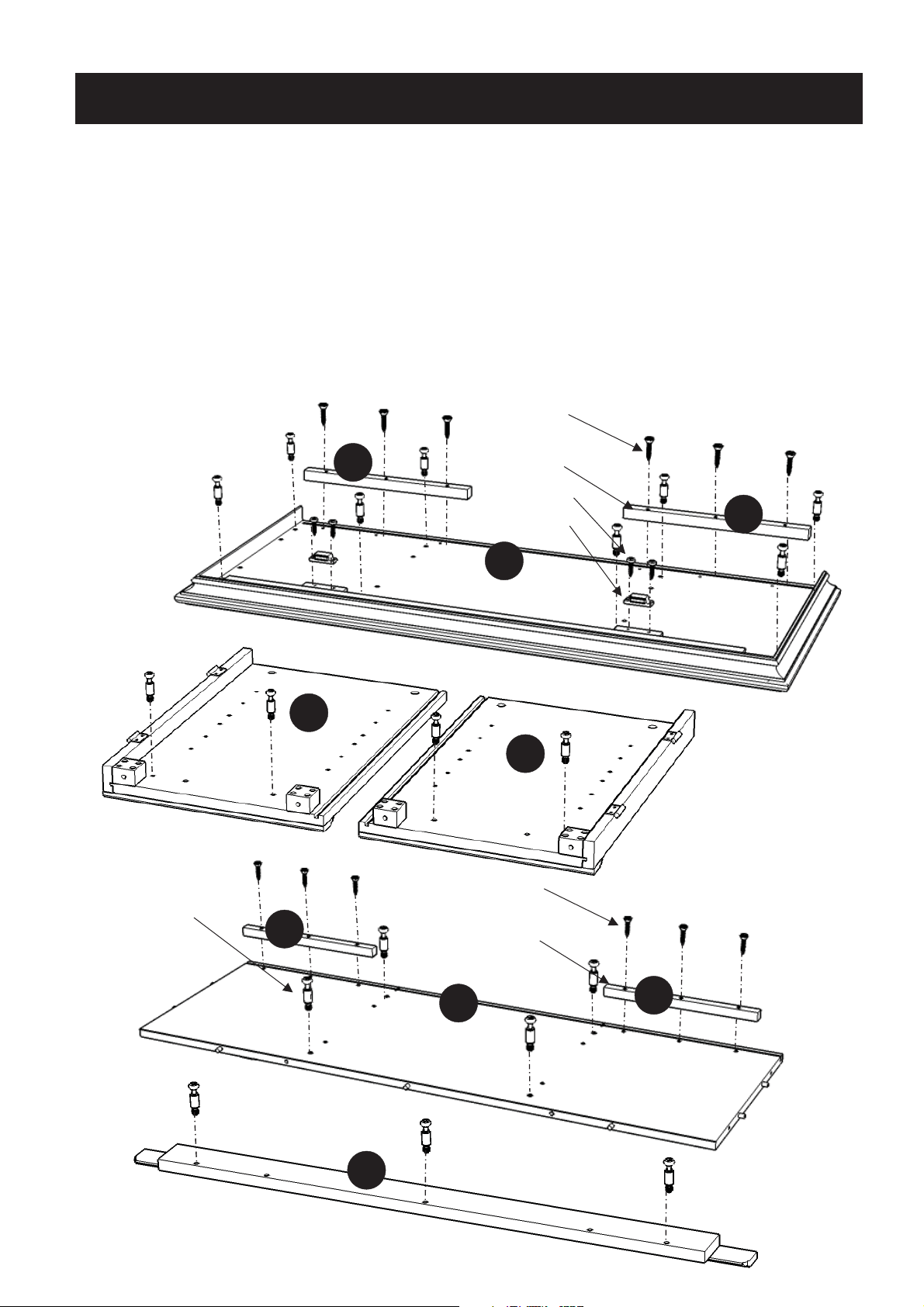
STEP 1
Attach 2X Wood Blocks (N) to Top (A) and Base (E) by using Wood Screws for Wood Block into
the pre-drilled holes.
Attach 2X Magnets to Top (A) by using Wood Screws in the pre-drilled holes.
Insert Cam Lock Screws into the pre-drilled holes of Top (A), Side Panel (B), (C),
Base (E) and Plinth (H).
Wood Screw
for Wood Block
Cam Lock Screw
N
B
N
Wood Block
Wood Screw
Magnet
A
C
Wood Screw
for Wood Block
Wood Block
N
H
E
E
N
Page 3

STEP 2
Assembly Instructions 3/4
Attach Middle Panels (D1) and (D2)
onto Base (E) with Cam Locks.
(see Figure 1)
B
E
Cam Lock
H
D1
D2
E
C
STEP 3
Attach Plinth (H) to Base (E)
with Cam Locks.
Attach Side Panel (B) and (C)
to unit with Cam Locks.
(see Figure 1)
STEP 4
Attach Legs (M)
into the pre-drilled holes
of unit and tighten.
M
M
Cam Lock
Figure 1
M
M
Page 4
Assembly Instructions 4/4
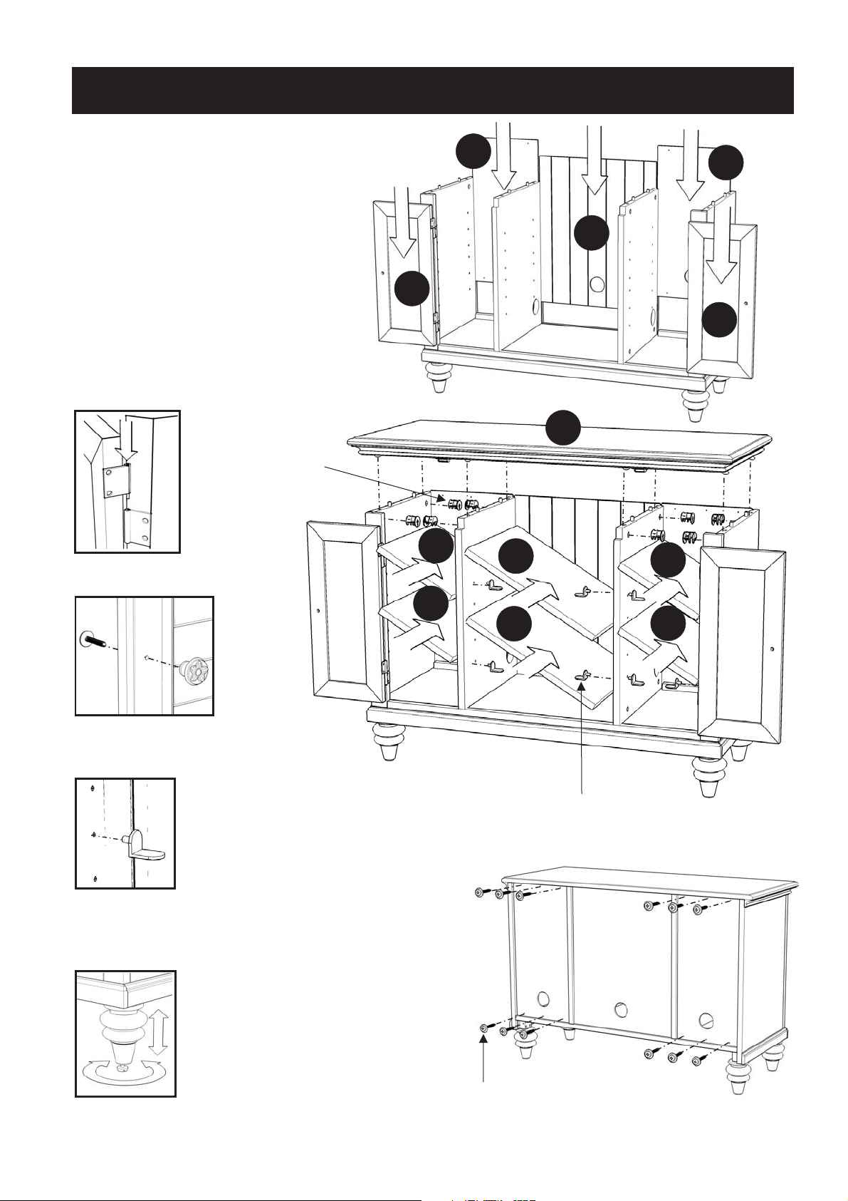
STEP 5
Slide Back Panels (I) and (J)
into place.
Attach Doors (K) and (L)
by sliding the door lift hinges
into the side panels lift hinges.
(see Figure 2)
Assemble Pull Handles to
Doors (K) and (L) with Machine Screws.
(see Figure 3)
Cam Lock
Figure 2
K
F
I
I
J
L
A
G
F
Figure 3
Figure 4
F
G
F
STEP 6
Place Top (A) onto unit with Cam Locks.
Insert Adjustable Pins into
side panels and middle panels at the desired level (see Figure 4),
then place Shelves (F) and (G) into position.
To level the unit,
adjust the adjustable levelers on
the bottom of legs. (see Figure 5)
Adjustable Pin
STEP 7
Figure 5
Insert 12X Wood Screws from
the back of the unit,
tighten up all the Wood Screws.
Note: Please make sure unit is level before tightening these screws.
Wood Screw
 Loading...