

Page 1
88 5539 100
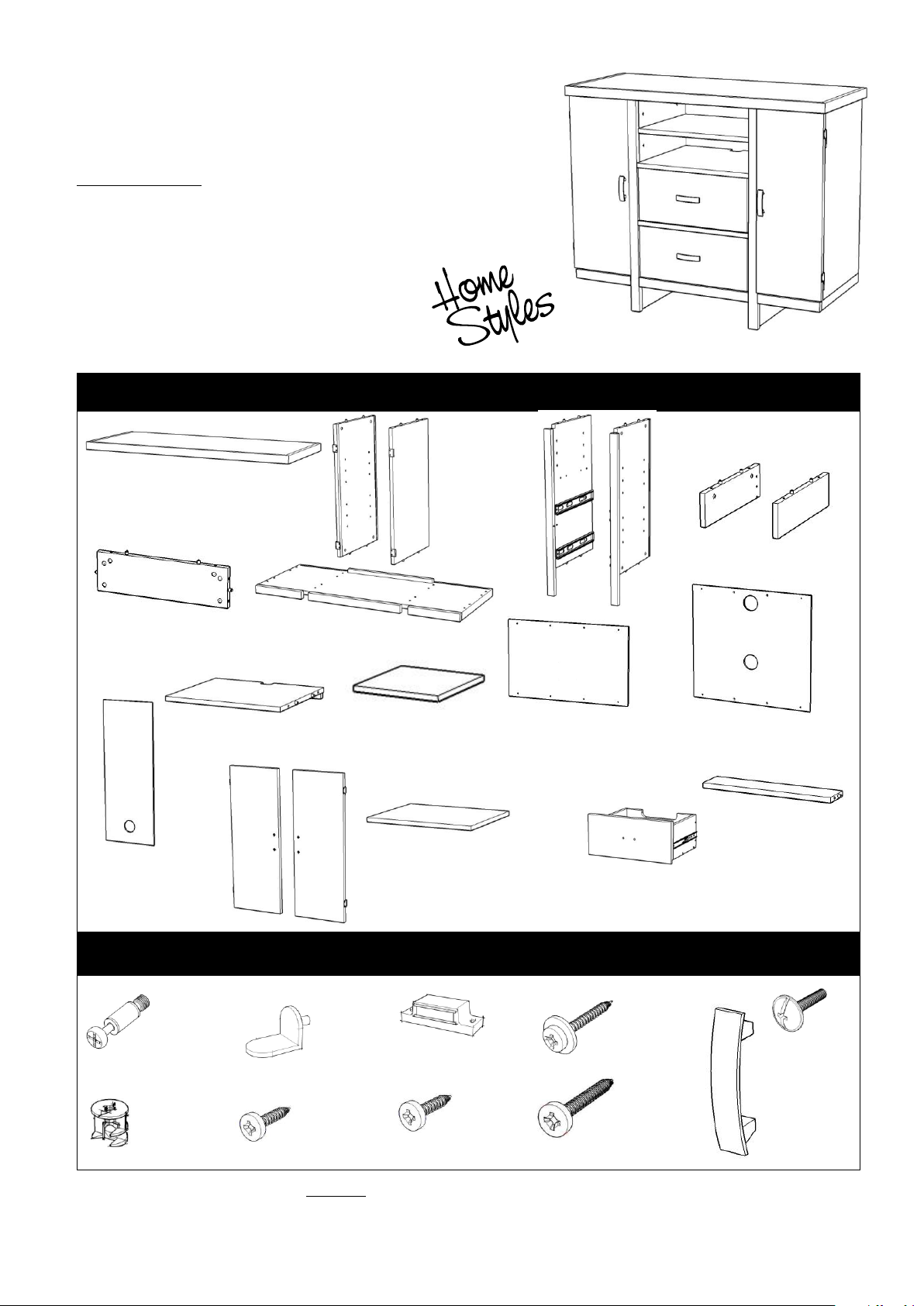
Geo Compact TV Credenza
IMPORTANT NOTE
Carefully remove all the parts from the carton and put
them individually on a soft cloth to prevent scratches
or other damages occuring to the wood parts.
We have taken great care in the design of this
product and request that you carefully and strictly
follow our assembly instructions to ensure a
completed product as it was designed.
Part List
A.
Top
1 pc.
H.
Foot
1 pc.
L.
Back Panel
2 pcs.
M.
Fixed Shelf
1 pc.
N.
Door
1 pc.
B.
Side Panel
1 pc.
I.
Base
1 pc.
O.
Door
1 pc.
P.
Shelf
4 pcs.
Q
Shelf
1 pc.
Middle Panel
C.
Side Panel
1 pc.
D.
E.
Middle Panel
1 pc.
1 pc.
F.
Foot
1 pc.
J.
Back Panel
1 pc.
R.
Drawer
2 pcs.
(Knock-Down Construction, please refer to the last page
of these instructions for steps to assemble drawers)
K.
Back Panel
1 pc.
S.
Front Rail
1 pc.
Foot
1 pc.
G.
Hardware List
Cam Lock Screw
32 pcs.(+2 extra)
Cam Lock
32 pcs.(+6 extra)
Tools required for assembly : Phillips screwdriver
Home Styles Consumer Assistance Line 888-680-7460 and 877-831-0319
Adjustable Pin
20 pcs.(+1 extra)
Wood Screw
for Drawer hinge
12 pcs.(+1 extra)
servicedesk@homestyles-furniture.com
Magnet
2 pcs.
Wood Screw
for Magnet
4 pcs.(+1 extra)
Wood Screw
for Back Panel
16 pcs.(+1 extra)
Wood Screw
for Drawer
26 pcs.(+1 extra)
Machine Screw
8 pcs.
Pull Handle
4 pcs.
Page 2
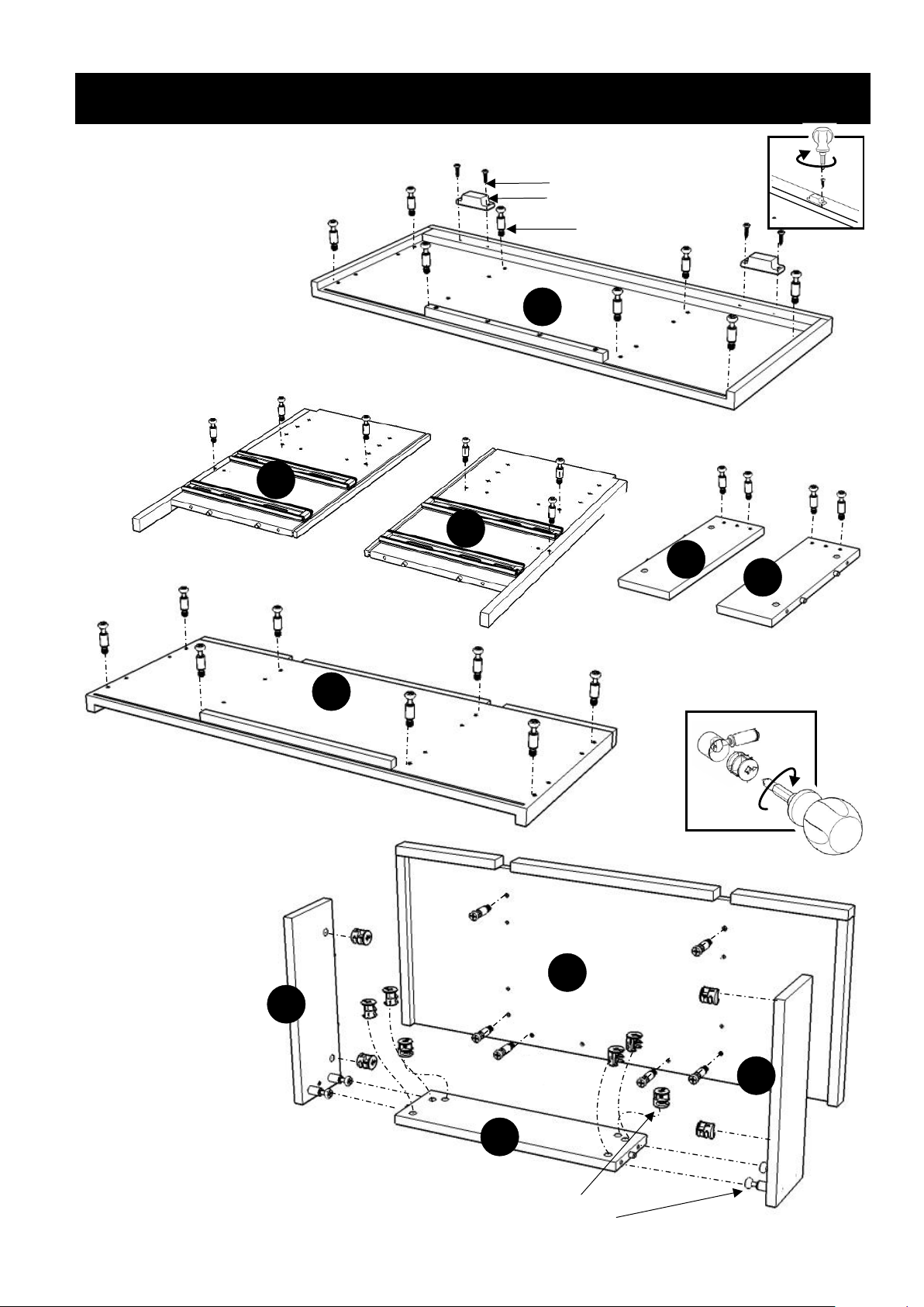
Assembly Instructions 2/5
H
FGD
E
STEP 1
Attach 2X Magnets to
Top (A) by using
Wood Screws
in the pre-drilled holes
(see Figure 1).
Insert Cam Lock Screws into the
pre-drilled holes of Top (A), Middle Panels (D), (E),
Feet (F), (G) and Base (I) with Cam Lock Screws.
Wood Screw
Magnet
Cam Lock Screw
Figure 1
A
STEP 2
Insert Cam Lock Screws
into the pre-drilled
holes of Base (I).
Assemble Foot (F),
(G) and (H) with
Cam Locks
(see Figure 2).
Attach Foot unit to
Base (I) with Cam Locks.
I
(Figure 2)
I
F
G
Cam Lock
Cam Lock Screw
Page 3

STEP 3
DEM
B
C
J
K
L
L
Assemble
Middle Panels (D)
and (E) with
Fixed Shelf (M) and
Front Rail (S),
using Cam Locks.
Assembly Instructions 3/5
Cam Lock Screws
Cam Lock
S
STEP 5
STEP 4
Attach Middle Panel unit and
Side Panels (B) and (C) to
base unit in Step 2 with
Cam Locks.
Slide Back Panels (J), (K) and (L)
into position.
Page 4

(Figure 3)
Q
ANOPPPPRR
(Figure 4)
Assembly Instructions 4/5
Adjustable Pin
(Figure 5)
STEP 6
Attach Doors (N) and (O) by sliding the door lift hinges into the side panels lift hinges.
(See figure 3)
Assemble Pull Handles to Doors with Machine Screws. (See figure 4)
Place Top (A) onto the unit with Cam Locks, then insert Adjustable Pins into side panels and
middle panels at the desired level. (See figure 5)
Place Shelves (P), (Q) and Drawer (R) into position.
(Figure 6)
STEP 7
Insert 16X Wood Screws from the back
of the unit, tighten up all the Wood Screws.
(See figure 5)
Note: Please make sure unit is level before tightening these screws.
Page 5

Drawer (R)
Assembly Instructions 5/5
R5
Figure 1
STEP 2
Attach R3 and R4 to the unit
with long wood screws (10X),
tighten halfway.
Attach R1 to R5 with
short wood screws (6X).
(see Figure 2)
Tighten all screws used in
drawer assembly.
R2
R3
Figure 2
STEP 1
Attach R2 to R5, using a
long
and wood screws (4X), tighten halfway.
(see Figure 1)
R2
R5
R1
Phillips screwdriver
R4
Figure 3
Part List
R1.
Front Part
2 pcs.
R2.
Back Part
2 pcs.
R3.
Side Part
2 pcs.
STEP 3
Assemble Pull Handle with
machine screws. (see Figure 3)
R4.
Side Part
2 pcs.
R5.
Base Part
2 pcs.
 Loading...