

Page 1
88 5516 13
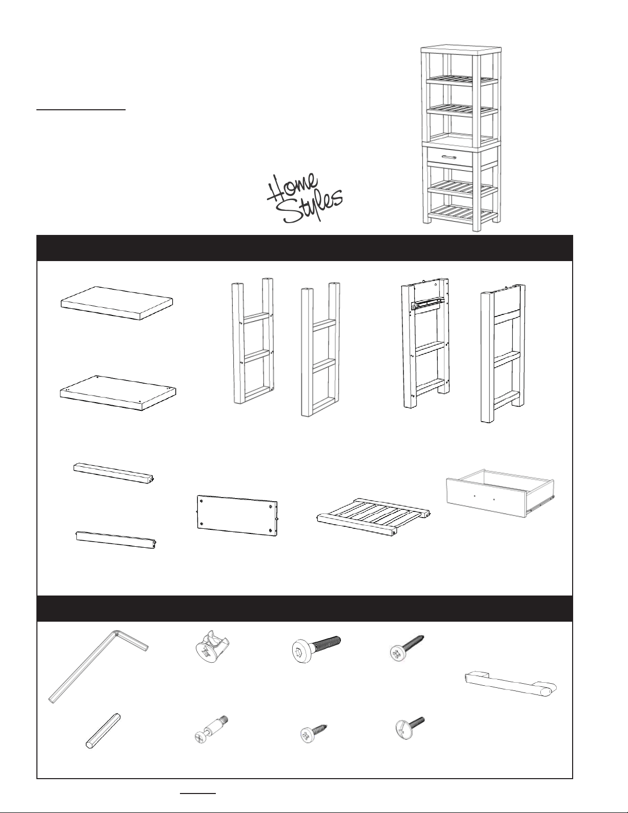
Barnside Media Tower
IMPORTANT NOTE
Carefully remove all the parts from the carton and put
them individually on a soft cloth to prevent scratches
or other damage occurring to the parts.
We have taken great care in the design of this
product and request that you carefully and strictly
follow our assembly instructions to ensure a
completed product as it was designed.
Part List
A.
Top
1 Pc.
B.
Top
1 Pc.
E.
Back Stretcher
1 Pc.
H.
Front Rail
1 Pc.
Hardware List
Hex Wrench
1 Pc.
C.
Frame
1 Pc.
I.
Back Panel
1 Pc.
Cam Lock
16 Pcs. (+4 extra)
D.
Frame
1 Pc.
Head Cap bolt
20 Pcs. (+1 extra)
J.
Shelf
4 Pcs.
Wood Screw (long)
8 Pcs. (+1 extra)
F.
Frame
1 Pc.
G.
Frame
1 Pc.
K.
Drawer
1 Pc.
(Please refer to the last page of these
instructions for drawer assembly steps)
Pull Handle
1 Pc.
Small Hex Wrench
1 Pc.
Cam Lock Screw
16 Pcs. (+1 extra)
Wood Screw (short)
6 Pcs. (+1 extra)
Machine Screw
2 Pcs.
Tools required for assembly : Phillips screwdriver Tools recommended for assembly : Level
Home Styles Consumer Assistance: www.homestyles-furniture.com,
Page 2
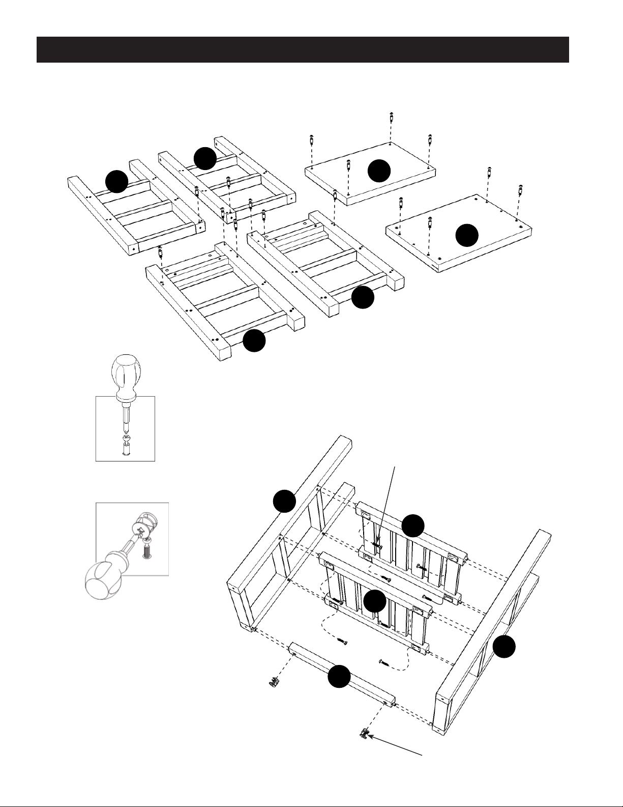
Assembly Instructions
IMPORTANT
* Please keep Hex Wrench in a safe place as you may need to tighten up the Head Cap Bolts in the future.
* Do not tighten up all the bolts until each part is properly assembled.
* Use a soft cloth between these parts and the fl oor.
D
A
C
B
G
2
/5
Figure 1
Figure 2
F
STEP 1
Insert Cam Lock Screws into pre-drilled holes of
Top (A), Top (B), Frame (C), Frame (D), Frame (F)
and Frame (G), then tighten.
(See fi gure 1)
Head Cap Bolt
C
J
J
E
STEP 2
Attach Shelves (J) to Frame (C) with Head Cap Bolts .
Attach Back Stretcher (E) to Frame (C) with Cam Locks.
(See fi gure 2)
Attach Frame (D) to unit with Head Cap Bolts and Cam Locks.
D
Cam Lock
Page 3

Assembly Instructions
3
/5
STEP 3
Turn the unit to its’ upright position.
Attach Top (A) to the unit with Cam Locks.
A
Cam Lock
STEP 5
Attach Shelves (J) to Frame (F) with
Head Cap Bolts.
Attach Front Rail (H), Back Panel (I)
to Frame (F) with Cam Locks.
Attach Frame (G) to unit with Head
Cap Bolts and Cam Locks.
B
Head Cap Bolt
F
STEP 4
Attach Top (B) to the unit with
Head Cap Bolts.
Cam Lock
H
I
J
J
G
Head Cap Bolt
Page 4

Assembly Instructions
STEP 6
Attach unit from Step 4 to unit from Step 5 with Cam Locks.
Cam Lock
4
/5
Figure 3
K
STEP 7
Slide Drawer (K) into position.
STEP 8
To level the unit, adjust the adjustable levelers on
the bottom of unit.
(See fi gure 3)
Page 5
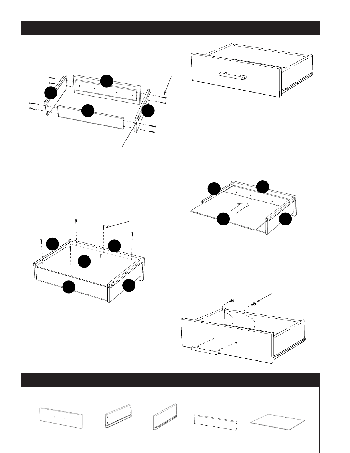
Drawer (K)
K2
K1
Wood Screw (long)
Assembly Instructions
5
/5
STEP 1
Attach K1, K2 and K3 using a Phillips screwdriver
and long wood screws (8X), tighten halfway.
Figure 1
K4
MAKE SURE ROLLER
IS ON THE BACK
K3
Attach K3 to K1, K4 using long wood screws (8X),
tighten halfway.
(See fi gure 1)
STEP 2
Slide K5 into grooves in K2 and K3. Be sure to
push K5 all the way forward so it meets K1.
(See fi gure 2)
Wood Screw (short)
K2
K5
K4
K1
K3
STEP 3
Insert short wood screws (6X) into pre-drilled holes
in K5, tighten screws.
(See fi gure 3)
K2
K5
K1
K3
Figure 2
Machine Screw
Figure 3
STEP 3
Attach Pull Handle with Machine Screws.
(See fi gure 4)
Tighten all screws used in drawer assembly.
Part List
K1.
Front Part
1 pc.
K2.
Side Part
1 pc.
K3.
Side Part
1 pc.
K4.
Back Part
1 pc.
Figure 4
K5.
Base Part
1 pc.
 Loading...