

Page 1
88504095 C
Kitchen Cart with
one Drawer, two Doors
and Adjustable Shelf
Dear Our Valuable Customers,
Please follow our assembly instructions in every step,
we guarantee that you will get the perfect merchandise.
Thank you so much for purchasing our quality products.
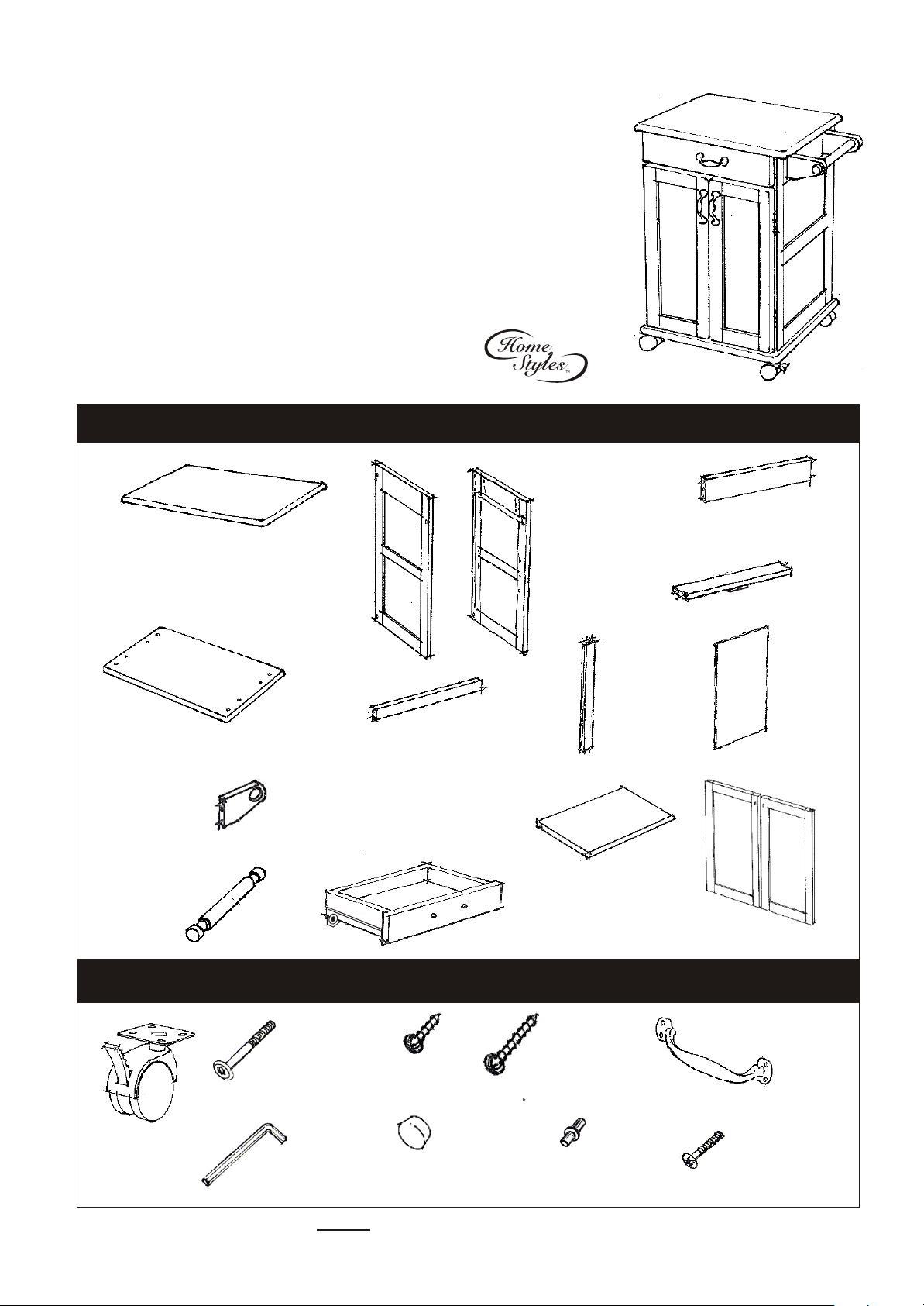
PART LIST
A.
Top
1 pc.
F.
Base Panel
1 pc.
J.
Handle Arms
2 pcs.
K.
Round Arms
1 pc.
Casual Attire For Today's Home
B.
Side Frame L.
1 pc.
Lower
Back Stretcher
L.
Drawer
(Knock-Down Construction, please
refer how to assemble the drawer
on the last page of this assembly
instructions).
1 pc.
Side Frame R.
G.
1 pc.
Adjustable Shelf
C.
1 pc.
H.
Middle
Back Stretcher
1 pc.
M.
1 pc.
Thai Patent Numbers 14892
D.
Upper
Back Stretcher
1 pc.
E.
Front Rail
1 pc.
I.
Back Panel
2 pcs.
O.
Door
2 pcs.
HARDWARE LIST
Head Cap Bolt
16 pcs.(+1 Extra)
Caster
2 with brake and
2 without brake
4 pcs.
Tools Required For Assembly : Philips screwdriver
Hex Wrench
1 pc.
Wood Screw
(for caster)
16 pcs. (+1 Extra)
Wood Plug
6 pcs.(+1 Extra)
Wood Screw 6 x 1”
Long (for Drawer)
8 pcs.(+1 Extra)
Adjustable Pin
4 pcs.(+1 Extra)
Pull Handle
3 pcs.
Machine Screw
for Pull Handle
6 pcs.
Page 2
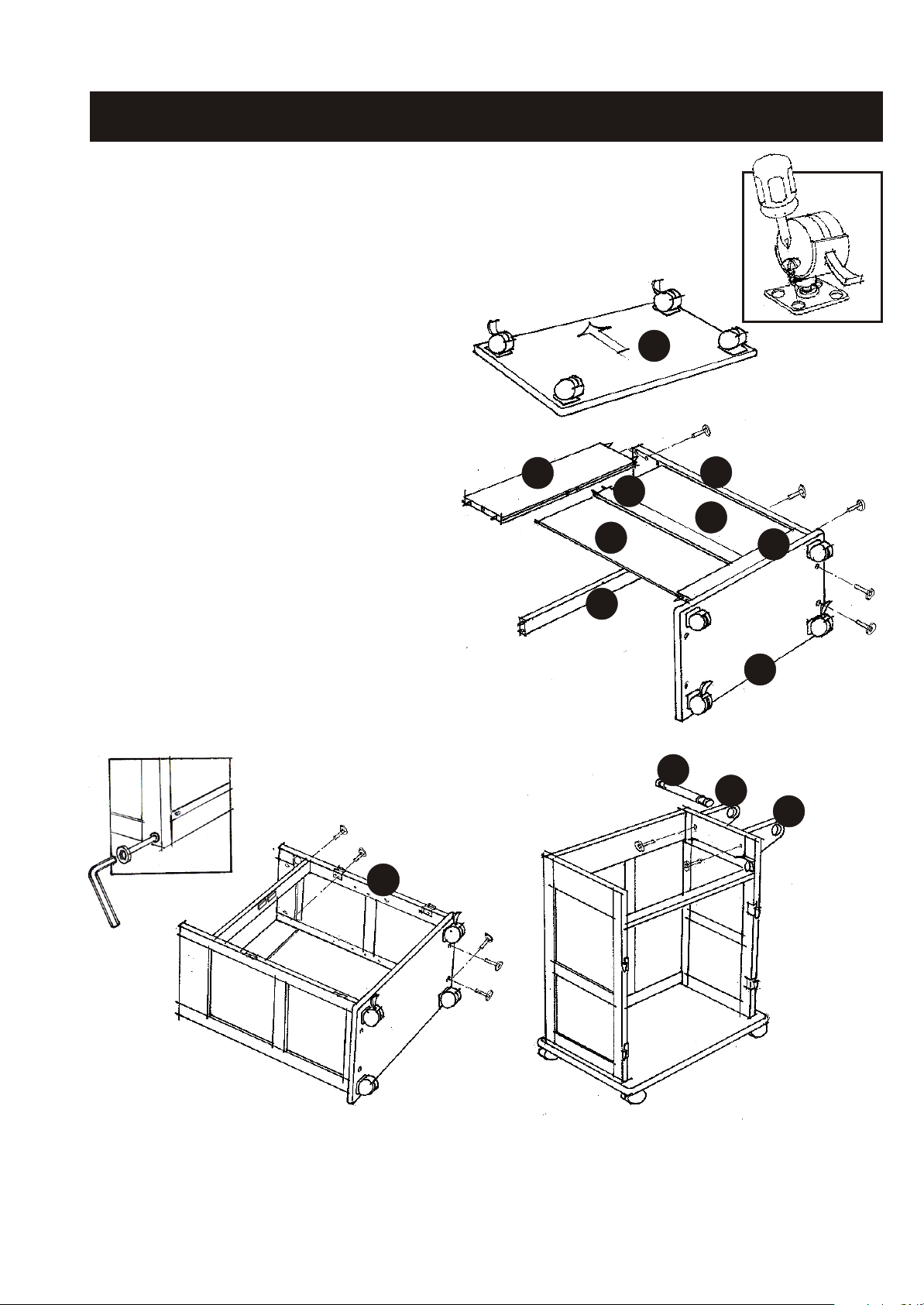
Assembly Instructions 2/4
IMPORTANT
Do not tighten up all the screws until each part is properly assembled.
You should keep Hex Wrench in the safe place as you may need to tighten up
the Head Cap Bolts in the future.
STEP 1
Attach 4 Casters to the under side of
the Base Panel (F) with Wood Screws (I),
put the 2 Casters with brakes in front as
you first need to lock the cart from moving.
STEP 2
Attach the Side Frame L (B) to the Base
Panel (F) with Head Cap Bolts.
Attach the Front Rail (E),Lower Back Stretcher (G)
to the Assembled Unit. Tighten the Head Cap Bolts.
Attach the Middle Back Stretcher (H) to the Lower
Back Stretcher (G), then slide the Back Panels (I) in place.
Attach the Upper Back Stretcher (D) to the Assembled Unit.
Tighten the Head Cap Bolts.
Tighten Head
Cap Bolt by
Hex Wrench.
D
E
F
B
H
I
I
G
F
K
J
J
C
STEP 3
Attach the Side Frame R (C) to the Assembled Unit, then tighten Head Cap Bolts.
Attach the Handle Arms (J) using Head Cap Bolts from the inside of the both Side Frames and
put the Round Arms (K) in place.
Page 3

Assembly Instructions 3/4
STEP 4
Attach the Top (A) to the Assembled Unit,
tighten all the Head Cap Bolts through
the Side Frame (B) and (C).
Top
Assembly
STEP 5
Attach the Doors (O) to the Assembled Unit.
A
B
C
Assemble the Door Pull Handles using the Machine Screws.
Insert the Adjustable Pins into the Side Panel, in the desired level. Place Adjustable Shelf (M)
and Slide the Drawer (L) in place.
L
Door Assembly
using Hinge
Pull Handle
Assembly
M
O
STEP 6
Cover all holes with
Wood Plugs
See the attached sheet for
Drawer Assembly Instructions.
Page 4

Drawer
Assembly Instructions 4/4
L4
(Fig)1
L1
L3
MAKE SURE ROLLER
IS ON THE BACK
(Fig) 2
Turn the assembled drawer over and slide the
Plywood Bottom Part (L5) into the grooves
on Side Parts (L1), (L3) and (L4). Be sure to push
the plywood all the way forward so it meets the
Front Part (L1).
(Fig) 3
Attach the Back Part (L2) to the assembled drawer. Using a
Philips screw driver, insert 1” screws (II) into each of the 4
L2
(Fig) 1
Line up Side Parts (L3) and (L4) to the
Front Part (L1). Be sure to follow the Arrow sign
sticker on the parts. Using a Philips screw driver,
insert 1” screws (II) into each of the 4 pre-drilled
holes in sides (L3) and (L4), then tighten half way.
L3
L1
(Fig)2
L5
L5
pre-drilled holes in sides (L3) and (L4), then tighten all
L4
screws.
(Fig)4
(Fig)3
* If you are missing any of these
parts, please contact our DMI
Customer Service Department
at 1-877-831-0319 or fax us at
1-800-755-2878.
Unit Part List
L1.
Front Part
1 pc.
L2.
Back Part
1 pc.
(Fig) 4
Assemble the Pull Handle
with Machine Screw on
the Front Part (L1).
L3.
Side Part(L)
1 pc.
L4.
Side Part(R)
1 pc.
L5.
Bottom Part
1 pc.
 Loading...