

Page 1
88 5012 941
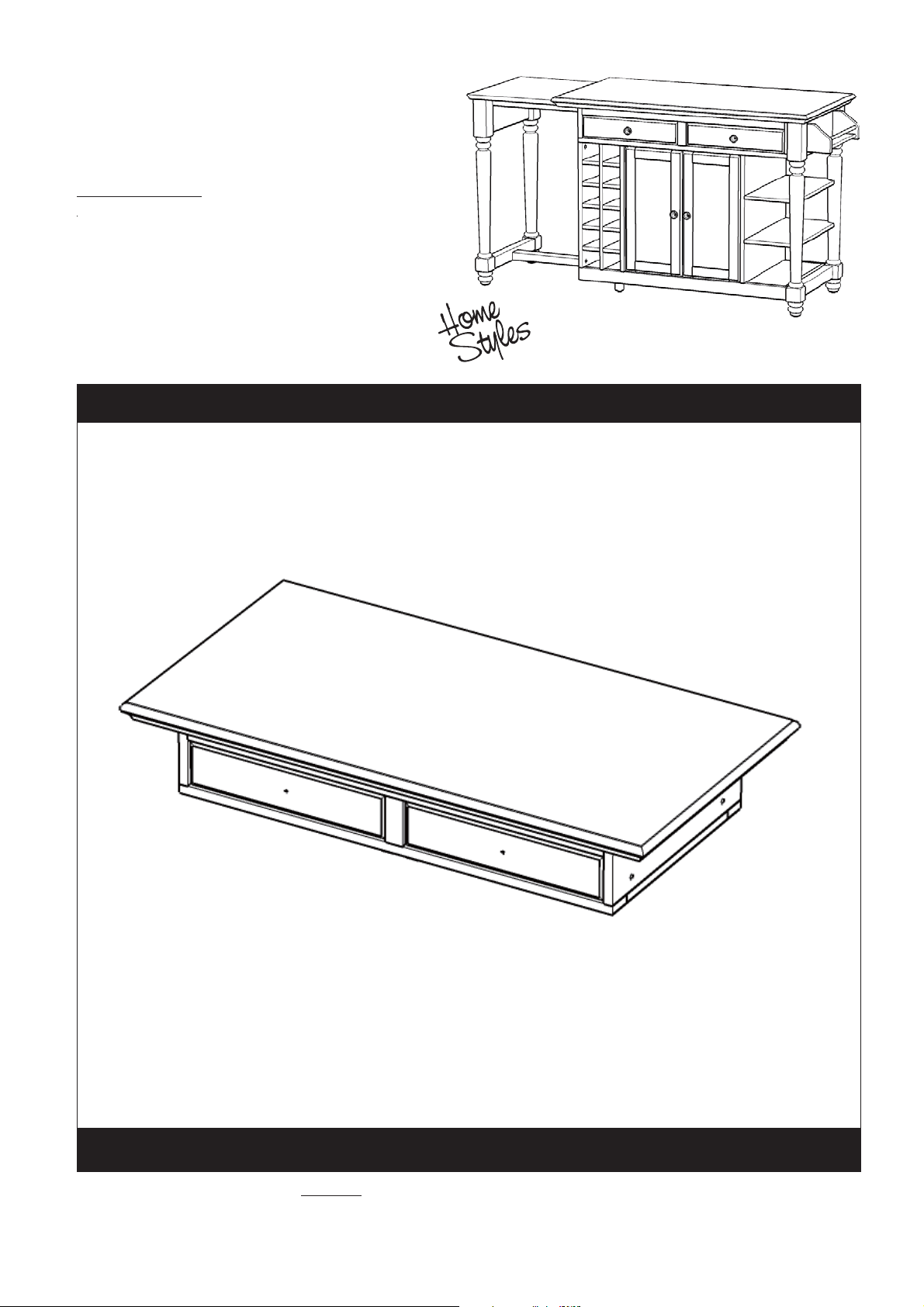
Grand Torino
Kitchen Island
IMPORTANT NOTE
Carefully remove all the parts from the carton and put
them individually on a soft cloth to prevent scratches
or other damages occuring to the wood parts.
We have taken great care in the design of this
product and request that you carefully and strictly
follow our assembly instructions to ensure a
completed product as it was designed.
Part List
A.
Top Unit
1 pc.
For assembly see instructions in carton 88 5012 942
Tools required for assembly : Tools recommended for assembly :Phillips screwdriver Level
Home Styles Consumer Assistance: www.homestyles-furniture.com,
servicedesk@homestyles-furniture.com, 888-680-7460, 877-831-0319
Page 2
88 5012 942
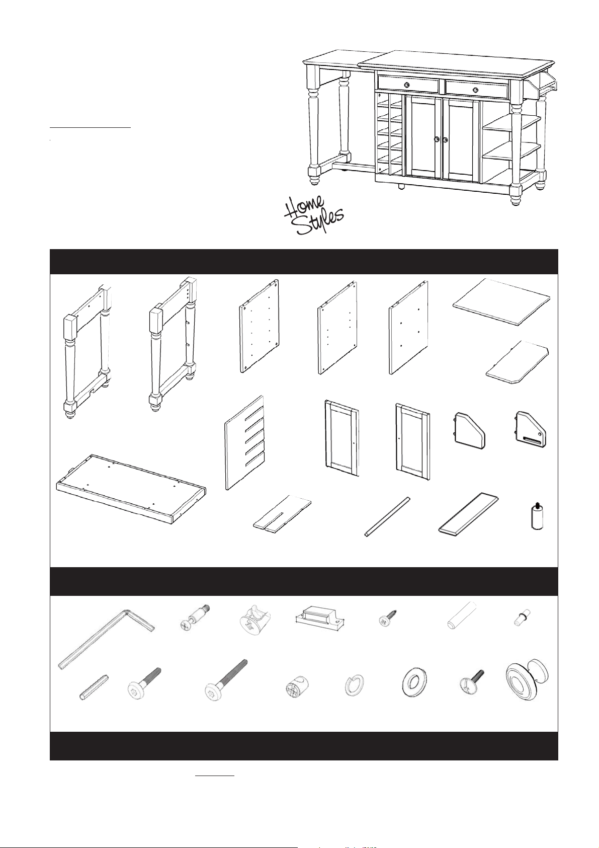
Grand Torino
Kitchen Island
IMPORTANT NOTE
Carefully remove all the parts from the carton and put
them individually on a soft cloth to prevent scratches
or other damages occuring to the wood parts.
We have taken great care in the design of this
product and request that you carefully and strictly
follow our assembly instructions to ensure a
completed product as it was designed.
Part List
G.
Shelf
1 pc.
B.
Side Frame
1 pc.
I.
Bottom
1 pc.
C.
Side Frame
1 pc.
Hardware List
Hex Wrench
1 pc.
Cam Lock Screw
4 pcs.(+1 extra)
D.
Side Panel
1 pc.
J.
Wine Grid
1 pc.
K.
Wine Grid
5 pcs.
Cam Lock
4 pcs.(+1 extra)
E.
Side Panel
1 pc.
L.
Door
2 pcs.
Magnet
4 pcs.
F.
Side Panel
1 pc.
P.
Pipe
1 pc.
WoodScrew
8 pcs. (+1 extra)
M.
Door
2 pcs.
N.
Side Rack
1 pc.
Q.
Base Rack
1 pc.
Wood Dowel
1 pcs. (+1 extra)
H.
Shelf
2 pcs.
O.
Side Rack
1 pc.
R.
Post
2 pcs.
Adjustable Pin
4 pcs. (+1 extra)
Small
Hex Wrench
1 pc.
Head Cap Bolt (short)
13 pcs. (+1 extra)
Head Cap Bolt (long)
8 pcs. (+1 extra)
Cross Dowel
8 pcs. (+1 extra)
Spring Washerl
2 pcs. (+1 extra)
Flat Washer
2 pcs. (+1 extra)
Machine Screw
8 pcs.
Knob
8 pcs.
Also need Part in carton 88 5012 941
Tools required for assembly : Tools recommended for assembly :Phillips screwdriver Level
Home Styles Consumer Assistance: www.homestyles-furniture.com,
servicedesk@homestyles-furniture.com, 888-680-7460, 877-831-0319
Page 3

Assembly Instructions 2/5
IMPORTANT
* Do not tighten up all the screws until each part is properly assembled.
* You should keep Hex Wrench in a safe place as you may need to tighten up the Head Cap Bolts in the future.
* After assembly, item must be level to work properly. Use the included adjustable levelers to level.
* Use a soft cloth between these parts and the floor.
Cam Lock
Wood Screw
Magnet
A
Cam Lock
I
D
Figure 1
K
K
K
K
K
Figure 2
E
STEP 1
Place Top Unit (A) upside down on a soft cloth.
Remove the drawers in Top Unit (A).
Attach Magnets to Top unit (A) using Wood
Screws. (see Figure 1)
Insert Cam Lock Screws into the pre-drilled
holes of Top Unit (A) and Bottom (I).
(see Figure 2)
STEP 2
Attach Wine Grid (K) to Side Panel (D) and (E).
Page 4

Assembly Instructions 3/5
Head Cap Bolt
(long)
I
F
STEP 3
Attach unit from Step 2 to Top Unit
(A) using Cam Locks, Head Cap
Bolts (long) and Cross Dowels.
(see Figure 3), (see Figure 4)
Attach Side Panel (F) to unit with
Head Cap Bolts (long) and Cross
Dowels.
Attach Bottom (I) to the unit using
Cam Locks, Head Cap Bolts (long)
and Cross Dowels.
A
STEP 4
Attach Base Rack (Q) and Pipe (P) to Side
Rack (N) and (O).
Attach rack unit to Side Frame (C) with Head
Cap Bolts (short). (see Figure 5)
Figure 4
Head Cap Bolt
(short)
O
FC
Q
P
Figure 5Figure 3
F
N
Page 5

STEP 5
Attach Shelves (H) to unit.
Attach unit from Step 4 to
unit with Head Cap Bolts
(short).
Attach Posts (R) to unit.
Slide out sub-top and wood
runner from unit.
Assembly Instructions 4/5
Head Cap Bolt (short)
Spring Washer
Flat Washer
R
R
B
H
Attach Side Frame (B) to
the unit with Flat Washers,
Spring Washers and Head
Cap Bolts (short).
(see Figure 6)
Wood Dowel
Figure 6
H
Wood Dowel
Figure 7
J
STEP 6
Turn the unit to its’ upright position.
Slide Wine Grid (J) into unit and
lock it in position by inserting
Wood Dowel into the hole located
in the rail directly above it.
(see Figure 7)
Page 6

L
M
Assembly Instructions 5/5
STEP 7
Assemble Pull Handles to drawers
and Doors (L), (M) with Machine
Screws. (see Figure 8)
Slide Drawers into position.
Attach Doors (L) and (M) by inserting
the lower spring pin into the hole until
it clicks and then do the same for the
upper spring pin. (see Figure 9)
G
Adjustable Pin
Figure 8
Figure 9
Insert Adjustable Pins into side panels
at the desired level. Place Shelf (G)
into position.
To level the unit, adjust the adjustable
levelers on the stationary frame legs
and the posts. (see Figure 10)
Note : Unit must be level to work
properly
Figure 10
STEP 8
To use top extension, pull out side
frame from the unit.
 Loading...