

Page 1
88 5010 941
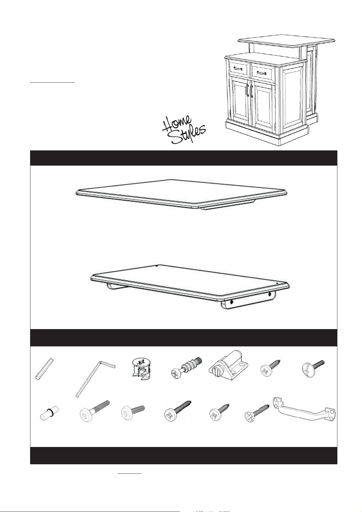
Woodridge Kitchen Island
IMPORTANT NOTE
Carefully remove all the parts from the carton and put
them individually on a soft cloth to prevent scratches
or other damages occuring to the wood parts.
We have taken great care in the design of this
product and request that you carefully and strictly
follow our assembly instructions to ensure a
completed product as it was designed.
Part List
A.
Top
1 pc.
B.
Top
1 pc.
Hardware List
Small
Hex Wrench
1 pc.
Hex Wrench
1 pc.
Cam Lock
36 pcs.(+1 extra)
Cam Lock Screw
36 pcs.(+1 extra)
Magnet
2 pcs.
Wood Screw for Magnet
8 pcs. (+1 extra)
Machine Screw
8 pcs.
Adjustable Pin
20 pcs. (+1 extra)
Head Cap Bolt
10 pcs. (+1 extra)
Head Cap Bolt (short)
4 pcs. (+1 extra)
Wood Screw (long)
16 pcs.(+1 extra)
Wood Screw (short)
8 pcs.(+1 extra)
Wood Screw for Plinth
2 pcs. (+1 extra)
Pull Handle
4 pcs.
For assembly see instructions in carton 88 5010 942
Tools required for assembly : Phillips screwdriver Tools recommended for assembly : Level
Home Styles Consumer Assistance Line 888-680-7460 and 877-831-0319
servicedesk@homestyles-furniture.com
Page 2
88 5010 942
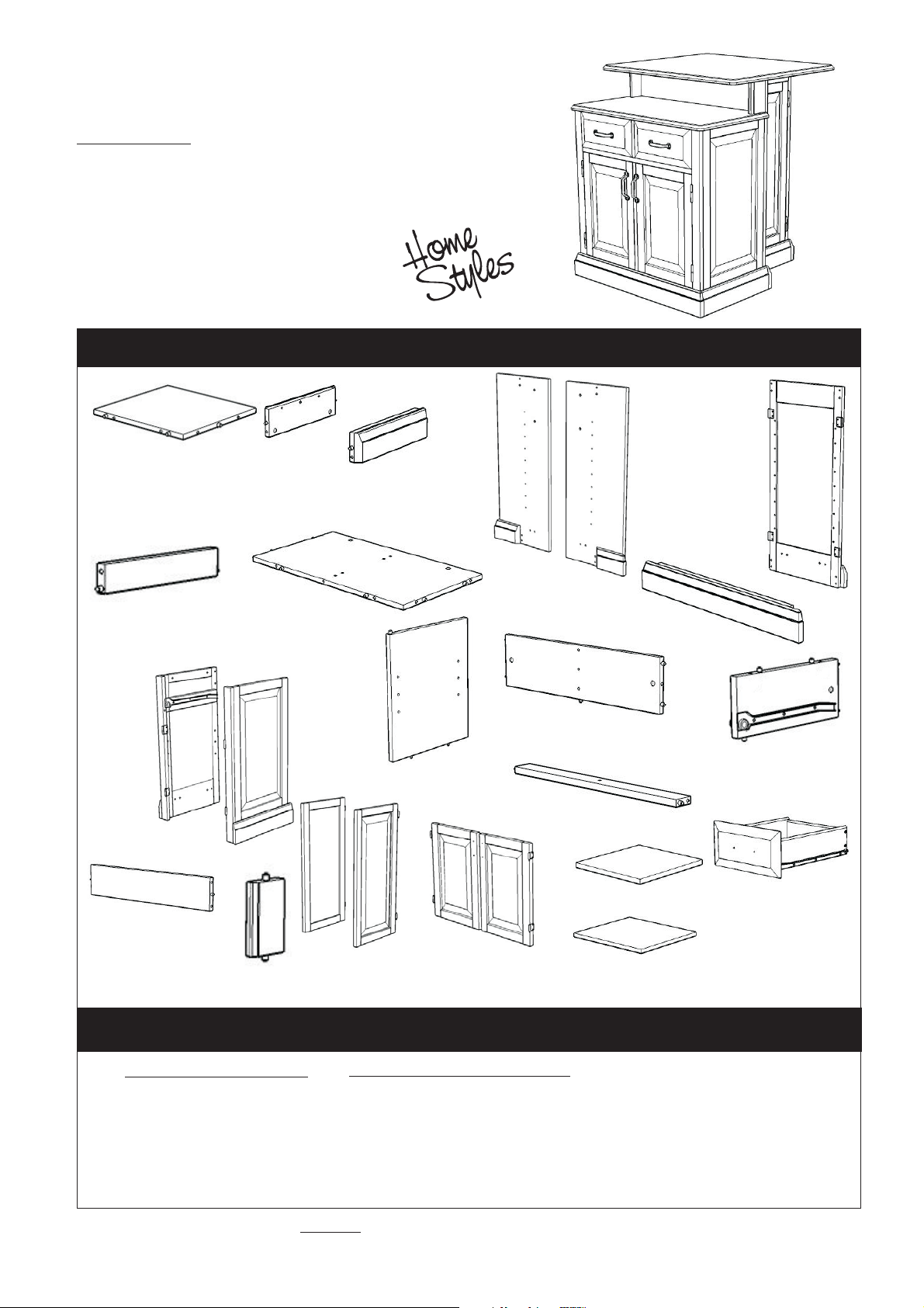
Woodridge Kitchen Island
IMPORTANT NOTE
Carefully remove all the parts from the carton and put
them individually on a soft cloth to prevent scratches
or other damages occuring to the wood parts.
We have taken great care in the design of this
product and request that you carefully and strictly
follow our assembly instructions to ensure a
completed product as it was designed.
Part List (in this carton)
C.
Base
1 pc.
L.
Side Frame
1 pc.
R.
Support
1 pc.
I.
Rail
2 pcs.
S.
Support
2 pcs.
D.
Plinth
1 pc.
E.
Plinth
1 pc.
J.
Base
1 pc.
M.
Side Frame
1 pc.
T.
Door
1 pc.
U.
Door
1 pc.
F.
Back Panel
1 pc.
Middle Panel
1 pc.
V.
Door
1 pc.
O.
Back Stretcher
1 pc.
N.
P.
Front Rail
1 pc.
W.
oor
1 pc.
X.
Shelf
3 pcs.
Y.
Shelf
2 pcs.
G.
Back Panel
1 pc.
K.
Plinth
1 pc.
H.
Front Frame
1 pc.
Q.
Divider
1 pc.
Z.
Drawer
2 pcs.
(Knock-Down Construction,
please refer to the last page
of these instructions for
drawer assembly steps)
Also need the following from carton 88 5010 941
Part List in carton 88 5010 941
Top (A)
Top (B)
1 pc.
1 pc.
Tools required for assembly : Phillips screwdriver Tools recommended for assembly : Level
Home Styles Consumer Assistance Line 888-680-7460 and 877-831-0319
servicedesk@homestyles-furniture.com
Hardware List in carton 88 5010 941
Hex Wrench
Small
Hex Wrench
Magnet
Cam Lock
Cam Lock Screw
Head Cap Bolt
Head Cap Bolt (short)
1 pc.
1 pc.
2 pcs.
37 pcs.
37 pcs.
11 pcs.
5 pcs.
Adjustable Pin
Wood Screw for Magnet
Wood Screw (long)
Wood Screw (short)
Wood Screw for Plinth
Machine Screw
Pull Handle
21 pcs.
9 pcs.
17 pcs.
9 pcs.
3 pcs.
8 pcs.
4 pcs.
Page 3
Assembly Instructions 2/6
IMPORTANT
* Do not tighten up all the screws until each part is properly assembled.
* You should keep Hex Wrench in a safe place as you may need to tighten up the Head Cap Bolts in the future.
* After assembly, item must be level to work properly. Use the included adjustable levelers to level.
STEP 1
Attach Back Panel (F) to Back Panel (G) as shown.
Wood Screw for Magnet
Attach 2X Magnets to
Back Panel (F) and (G) by using
Wood Screws in the pre-drilled holes
(See figure 1).
Insert Cam Lock Screws into
the pre-drilled holes of
Back Panel
(F) and (G).
STEP 2
Insert Cam Lock Screws into the
pre-drilled holes of Front Frame(H),
Plinth (D) and (E).
Magnet
Magnet
Figure 1
F
G
Cam Lock Screw
Cam Lock Screw
D
D
C
H
E
Cam Lock
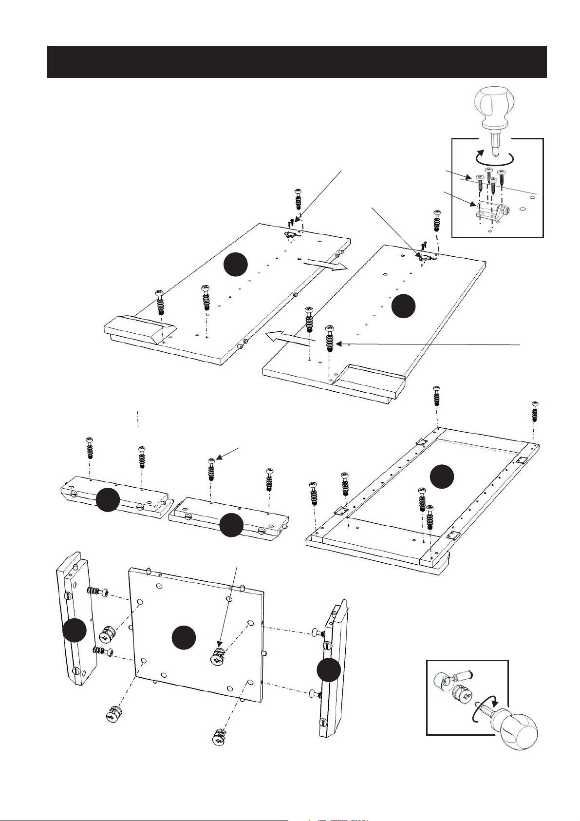
STEP 3
Attach Plinth (D) and (E)
to Base (C) with Cam Locks.
(See figure 2)
E
Figure 2
Page 4

STEP 4
Assembly Instructions 3/6
Attach Rails (I) and base unit in Step 3
to back panel unit in Step 2 with
Cam Locks.
Place Front Frame (H) onto unit
with Cam Locks.
E
H
H
I
I
H
O
I
K
L
STEP 5
Insert Cam Lock Screws into the
pre-drilled holes of Plinth (K), Side Frame (L) and (M), Back Stretcher (O).
M
Page 5

STEP 5
Attach Middle Panel (N) to Base (J)
with Head Cap Bolts.
Assembly Instructions 4/6
P
Attach Plinth (K) and Side Panel (L)
to Base (J) with Cam Locks and
Wood Screw.
Attach Front Rail (P) to unit
with Cam Lock.
Wood Screw
Q
K
N
L
J
Head Cap Bolt
STEP 6
O
Attach Back Stretcher (O) and
Divider (Q) to unit with Cam Locks.
Wood Screw
STEP 7
Place Top (B) onto unit with Head Cap Bolts.
M
Attach Side Panel (M) to unit
with Cam Lock and Wood Screw.
B
Page 6

Assembly Instructions 5/6
Head Cap Bolt
(short)
STEP 8
Assemble Supports (R) and (S) with
Cam Lock Screws and Cam Locks.
Attach unit in Step 4, Step 7 and
support unit with Cam Lock and
Head Cap Bolts (short).
Head Cap Bolt
(short)
Head Cap Bolt
A
S
Cam Lock Screw
Cam Lock
R
Cam Lock Screw
Attach Doors (U) and (T) by
sliding the door lift hinges into
the side panels lift hinges.
(See figure 3)
S
Cam Lock
STEP 9
U
X
T
X
X
STEP 10
Attach Doors (V) and (W) by sliding
the door lift hinges into the side panels
lift hinges.
Assemble Pull Handles to Doors with
Machine Screws. (See figure 4)
Insert Adjustable Pins into
side panels at the desired level.
Place Shelves (Y) and Drawers (Z)
into position.
Adjustable Pin
Figure 3
Figure 4
Z
V
Y
Place Top (A) onto unit with
Head Cap Bolts.
Insert Adjustable Pins into
side panels at the desired level.
Place Shelves (X) into position.
Z
W
Y
To level the unit, adjust the adjustable
levelers on the bottom of unit. (See figure 5)
Adjustable Pin
Figure 5
Page 7

Drawer (Z)
Assembly Instructions 6/6
Z3
Z2
Figure 1
MAKE SURE ROLLER
IS ON THE BACK
STEP 2
Slide Z5 into the grooves in Z3
and Z4. Be sure to push T5 all
the way forward so it meets Z1.
(see Figure 2)
Z1
Z3
Z5
Z1
Z4
STEP 1
Attach Z1 to Z3 andZ4,
using a
and wood screws ,
tighten halfway.
Attach Z2 to Z3 and Z4 using
long
tighten halfway. (see Figure 1)
Z3
Z5
Figure 2
Z2
Phillips screwdriver
long
wood screws ,
(4X)
Z1
Z4
(4X)
Z4
Z2
STEP 3
Insert wood screws (4X)
into the pre-drilled holes in Z5,
tighten screws. (see Figure 3)
short
Part List
Z1.
Front Part
2 pcs.
Z2.
Back Part
2 pcs.
Figure 3
STEP 4
Assemble Pull Handle with
machine screws. (see Figure 4)
Tighten all screws used in drawer assembly.
Z3.
Side Part
2 pcs.
Z4.
Side Part
2 pcs.
Figure 4
Z5.
Base Part
2 pcs.
 Loading...