

Page 1
88 4528 95
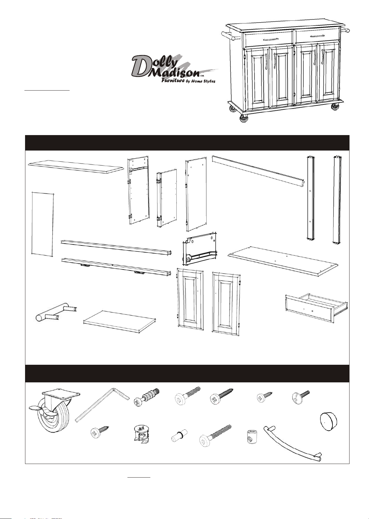
Wood Top Kitchen Cart
(Black Finish)
IMPORTANT NOTE
Carefully remove all the parts from the carton and put them individually
on a soft cloth to prevent scratches or other damages occuring to the wood parts.
We have taken great care in the design of this product and request that you carefully
and strictly follow our assembly instructions to ensure a completed product as it was designed.
PART LIST
H.
Back Panel
4 pcs.
M.
Side Bar
2 pcs.
A.
Top
1 pc.
B.
Side Panel
1 pc.
I.
Front Piece
1 pc.
J.
Front Piece
1 pc.
N.
Shelf
2 pcs.
C.
Middle Panel
1 pc.
Door
2 pcs.
O.
D.
Side Panel
1 pc.
K.
Divider
1 pc.
P.
Door
2 pcs.
E.
Back Stretcher
2 pcs.
F.
Back Piece
1 pc.
G.
Back Piece
2 pcs.
L.
Base
1 pc.
Q.
KD. Drawer
2 pcs.
(Knock-Down Construction,
please refer to the last page of
instructions for steps to complete
assembling drawers)
HARDWARE LIST
Hex Wrench
1 pc.
Caster
two lock
two non-lock
4 pcs.
Tools Required For Assembly : Phillips screwdriver
Wood Screw
for Caster
16 pcs. (+1 extra)
Cam Lock Screw
6 pcs. (+1 extra)
Cam Lock
6 pcs. (+1 extra)
Home Styles Consumer Assistance Line 888-680-7460 and 877-831-0319
servicedesk@homestyles-furniture.com
Head Cap Bolt
12 pcs. (+1extra)
Adjustable Pin
8 pcs. (+1 extra)
Wood Screw (long)
for Drawer Side Part
16 pcs. (+1 extra)
Head Cap Bolt (long)
7 pcs. (+1extra)
Wood Screw (short)
for Drawer Base Part
12 pcs. (+1 extra)
Cross Dowel
7 pcs. (+1extra)
Pull Handle
6 pcs.
Machine Screw
for Pull Handle
12 pcs.
Wood Plug
9 pcs.
(+1 extra)
Page 2
Assembly Instructions 2/5
IMPORTANT
Do not tighten up all the screws until each part is properly assembled.
You should keep Hex Wrench in a safe place as you may need to
tighten up the Head Cap Bolts in the future.
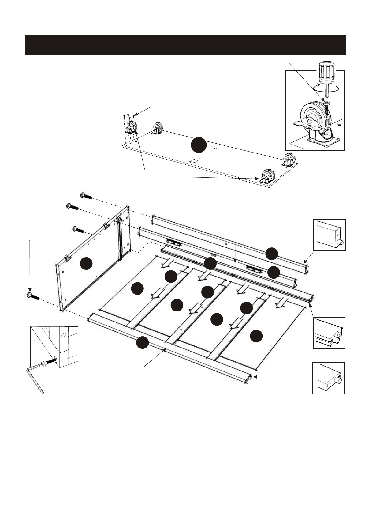
STEP 1
Attach the two locking Casters
to the front of the Base (L).
Attach the two non-locking
casters to the back of the
Base (L). (See figure 1)
(Note : The ‘Arrow’ sticker
indicates the front of the base.)
Head Cap Bolt
Wood Screw
L
Locking Caster
Wood Screw
(Figure 1)
Upper Position
I
B
G
H
H
E
J
F
G
H
H
E
Lower Position
Tighten Head
Cap Bolt by
Hex Wrench.
STEP 2
Attach Back Stretcher (E) to Side Panel (B) at the lower position with Head Cap Bolt.
Attach Back Pieces (F) and (G) to the Back Stretcher (E), then slide Back Panels (H) in place.
Attach Back Stretcher (E) to the unit at upper position.
Tighten the Head Cap Bolt.
Attach Front Pieces (I) and (J) to the unit with Head Cap Bolts.
Page 3

C
STEP 3
Attach Divider (K) in between Front Pieces
(I) and (J).
F
K
Instructions 3/5
I
J
D
Head Cap Bolt
Attach Middle Panel (C) to Back Piece (F).
Attach Side Panel (D) to the unit with Head Cap Bolts.
Cross Dowel
L
STEP 4
Attach Base (L) from Step 1
to the unit, using Cross Dowels
and Head Cap Bolts (long).
Head Cap Bolt (long)
Page 4

STEP 5
Put Cam Lock Screws into the
pre-drilled holes in Top (A).
Cam Lock
M
K
A
Assembly Instructions 4/5
Cam Lock Screw
A
Head Cap Bolt
(long)
Cross Dowel
M
STEP 6
Attach Side Bar (M) to the unit
with Head Cap Bolts.
Insert the Cross Dowel into
the hole of Divider (K) and
tighten Head Cap Bolt (long)
from the back of unit.
N
N
Adjustable Pin
Figure 1
Figure 2
STEP 7
Attach Pull Handles to the
Doors (O) and (P) using Machine
Screws. (See figure 1)
O
Q
Head Cap Bolt
P
O
Place Top (A) onto the unit,
using Cam Locks.
Insert Adjustable Pins into
the side panels and middle
panel at the desired level.
Place Shelves (N) into position.
Q
Attach the Doors (O) and (P) to
the side panels and middle panel
slide the door lift hinges into the
side panel and middle panel
lift hinges. (See figure 2)
Slide the Drawers (Q) into place.
Cover up all holes with
Wood Plug. (See figure 3)
P
Figure 3
Page 5

Drawer
Assembly Instructions 5/5
Q3
(Figure 1)
Q2
MAKE SURE ROLLER
IS ON THE BACK
STEP 2
Slide Q5 into the grooves in Q3
and Q4. Be sure to push the
Q5 all the way forward so
it meets the Q1. (See figure 2)
Q3
Q5
(Figure 3)
Q2
Q1
Q1
Q4
Q4
Q3
(Figure 2)
STEP 1
Attach Q1 to Q3 and Q4, using
a Phillips screwdriver and
the long wood screws (4X),
tighten halfway.
Attach Q2 to Q3 and Q4 using
the long wood screws (4X),
tighten halfway. (See figure 1)
Q1
Q5
Q4
Q2
* If you are missing any
of these parts, please
contact our DMI
Customer Service
Department at
1-877-831-0319 or fax
(Figure 4)
us at 1-800-755-2878.
STEP 3
Insert the short wood screws (6X)
into the pre-drilled holes in Q5,
tighten screws. (See figure 3)
Tighten all screws used in
drawer assembly.
Part List
Q1.
Front Part
2 pcs.
Q2.
Back Part
2 pcs.
Q3.
Side Part
2 pcs.
Q4.
Side Part
2 pcs.
STEP 4
Attach hardware pulls with
machine screws.
(See figure 4)
Q5.
Base Part
2 pcs.
 Loading...