

Page 1
20 05436 0772
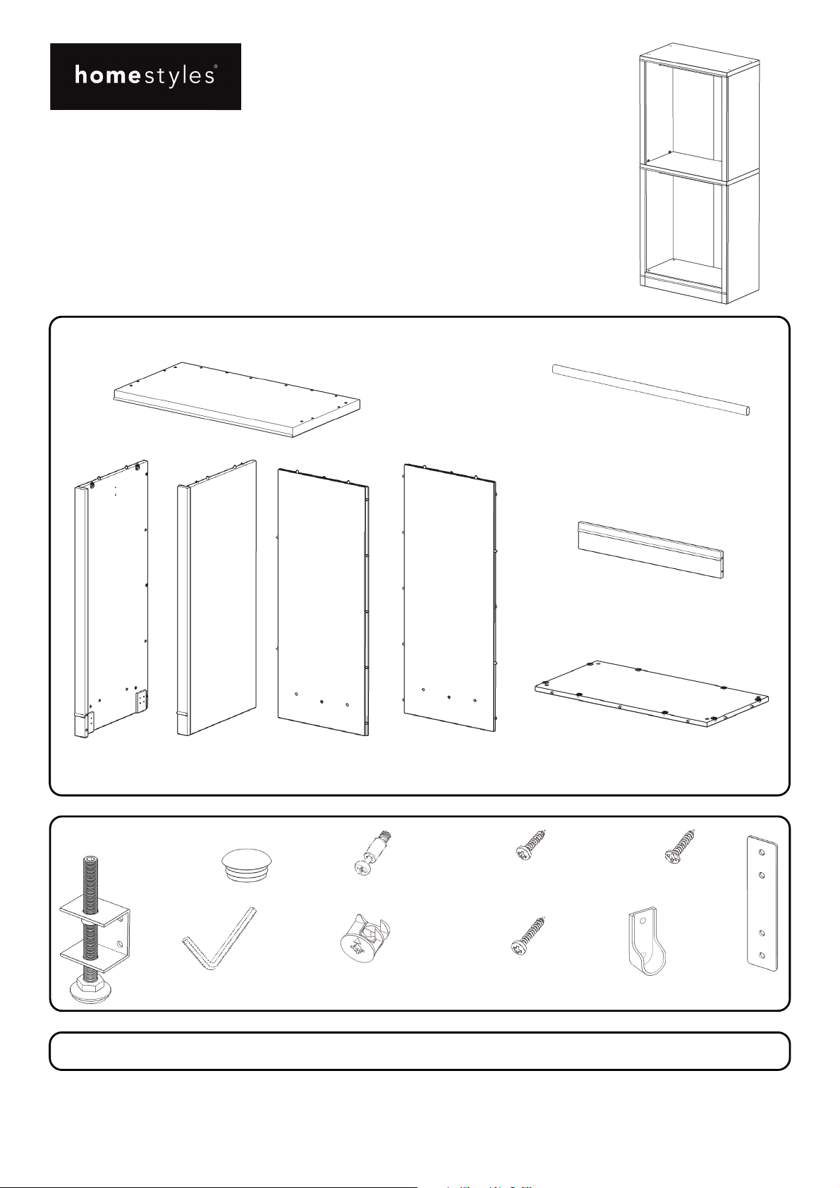
Closet Wall Hanging Unit
IMPORTANT
Carefully remove all the parts from the carton and
place them individually on a soft cloth to prevent
scratches or other damage.
Carefully and strictly follow these assembly instructions
to ensure a completed product as designed.
Do not use power tools above 8 volts to assemble.
Part List
F.
To p
1 pc.
H.
Side Panel
1 pc.
I.
Side Panel
1 pc.
J.
Back Panel
1 pc.
K.
Back Panel
1 pc.
G.
Rod
2 pcs.
L.
Plinth
1 pc.
M.
Bottom
1 pc.
Hardware List
M3x15
Wood Screw for
Bracket
8 pcs. (+1 extra)
M3x19
Wood Screw for
Leveler
16 pcs. (+1 extra)
Leveler
4 pcs.
Plug
4 pcs. (+1 extra)
Hex Wrench
1 pc.
Cam Lock Screw
4 pcs. (+1 extra)
Cam Lock
4 pcs. (+2 extra)
Carton 20 05436 0771 is also needed for assembly.
Tool(s) required for assembly: Phillips screwdriver, Level, Drill (8 volts or less), 3/8” Drill Bit
Home Styles Customer Service: www.homestyles-furniture.com,
servicedesk@homestyles-furniture.com,
888-680-7460, 877-831-0319
M3 x1.5 6
Wood Screw for
Rod Support
8 pcs. (+1 extra)
Rod Support
4 pcs.
Bracket
2 pcs.
Page 2
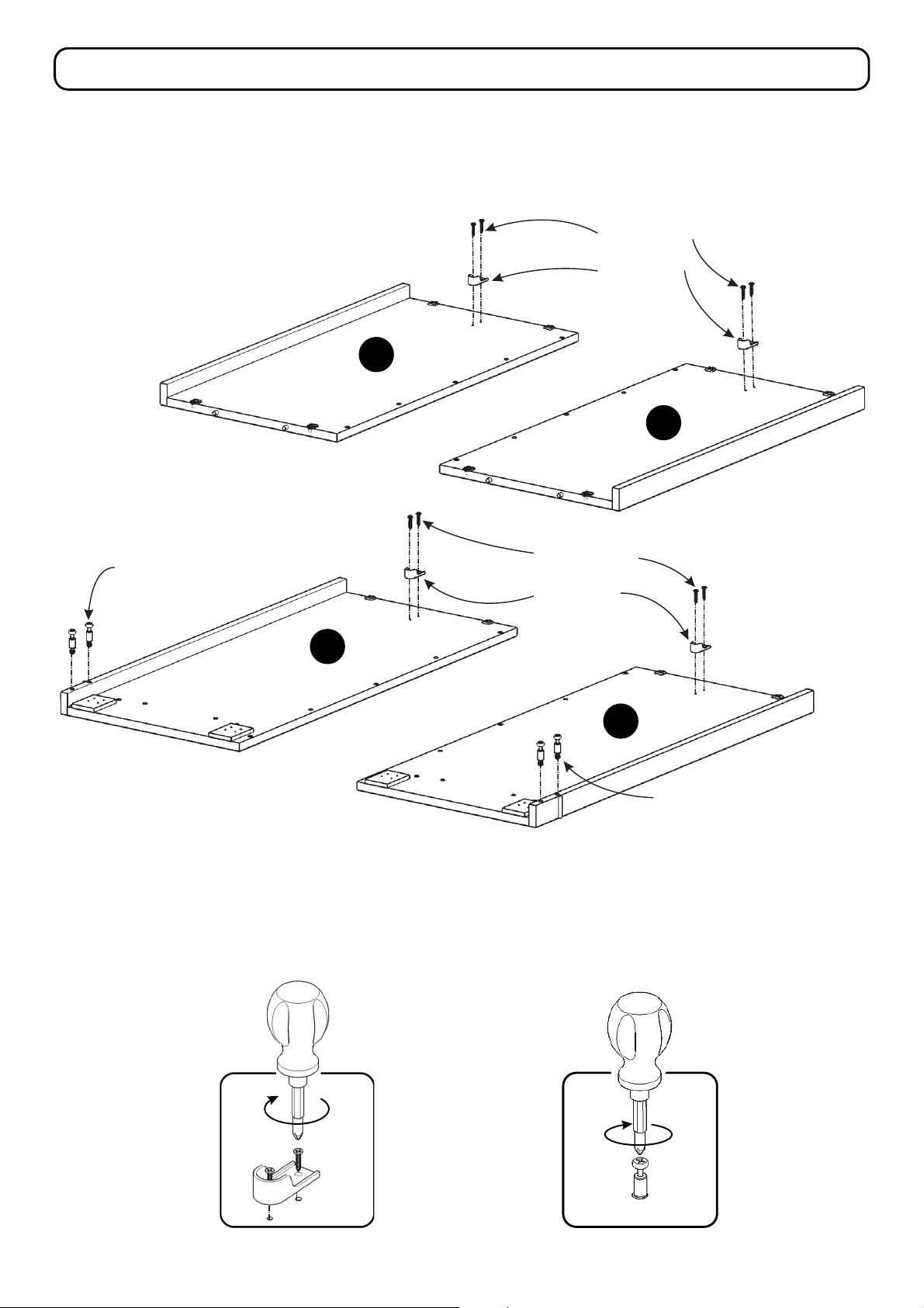
Assembly Instructions 2/8
IMPORTANT
Use a soft cloth between these parts and the floor.
Do not use power tools above 8 volts to assemble.
Do not tighten all the bolts until each part is properly assembled.
The unit must be level to work properly. Use the included adjustable levelers to level.
Keep Hex Wrench as the bolts may need to be tightened in the future.
B
Wood Screw for
Rod Support
Rod Support
C
Wood Screw for
Cam Lock Screw
Rod Support
Rod Support
H
I
Cam Lock Screw
STEP 1
Attach Rod Supports to Side Panels (B), (C), (H) and (I) with Wood Screws for Rod Support
into pre-drilled holes (See Figure 1).
Insert Cam Lock Screws into pre-drilled holes in Side Panels (H) and (I), then tighten.
(See Figure 2)
Figure 1
Figure 2
Page 3
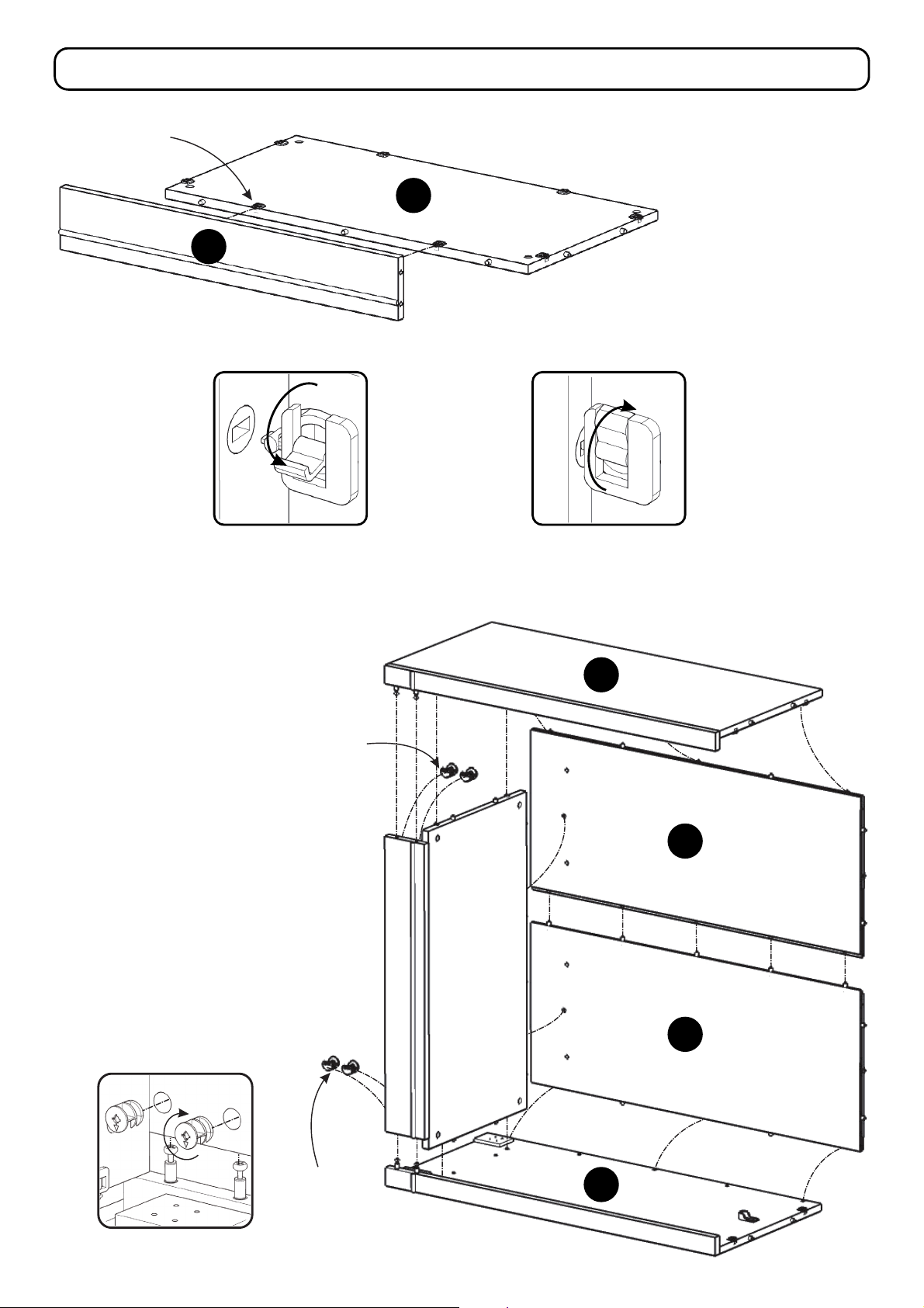
Lock
Assembly Instructions 3/8
M
STEP 2
L
PlinthAttach (L) to Bottom (M),
then flip Locks. (See Figures 3 and 4)
Figure 3 Figure 4
Cam Lock
STEP 3
Attach unit to Side Panel (I) with
Cam Locks, then flip Locks.
(See Figure 5)
Attach Back Panels (K) and (J) to unit,
then flip Locks.
H
J
Attach Side Panel (H) to unit with
Cam Locks, then flip Locks.
Cam Lock
Figure 5
K
I
Page 4

Assembly Instructions 4/8
Attach Levelers to bottom of unit with
STEP 4
Wood Screws for Levelers into
pre-drilled holes (See Figure 6).
Figure 6
Wood Screw for Leveler
Leveler
Lock
STEP 5
Attach Top (F) to unit, then flip Locks.
F
Page 5

STEP 6
Attach Back Panel (D) to
Side Panel (B), then flip Locks.
Assembly Instructions 5/8
B
Attach Back Panel (E) to
Side Panel (C), then flip Locks.
Attach unit to unit.
Lock
A
D
E
C
STEP 7
Attach Top (A) to unit, then flip Locks.
Page 6

Assembly Instructions 6/8
STEP 8
Place top unit onto
base unit, then flip
Locks.
Lock
G
G
Figure 7
Figure 8
Figure 9
Plug
STEP 9
Place unit at desired location.
Note: If assembling multiple Closet Wall Units together,
place all units at desired location.
Level unit(s) by adjusting the adjustable
levelers on bottom of unit(s). (See Figure 7)
Note: Unit(s) must be level to proceed.
Cover all holes with Plugs. (See Figure 8)
Place Rods (G) into position. (See Figure 9)
Page 7

Assembly Instructions 7/8
IMPORTANT
To help reduce the risk of the unit tipping over, the Tip-over Restraint must be installed following these instructions exactly.
STEP 10
Place unit at desired location.
Pre-drilled hole
at top of unit
Drill a 3/8” hole in wall in-line with
the pre-drilled hole at top of unit.
Move unit.
Insert Anchor into the wall hole
and attach Bracket with Wall Screw.
Attach Bracket at pre-drilled hole
at top of unit with Wood Screw.
Anchor in wall
3/8” wall hole
Tie end
Lock end
Bracket at
top of unit
Bracket
on wall
Wall Screw
Wood Screw
Move unit back into place.
If assembling multiple Closet Wall Units
together, go to and complete Step 11 now,
then return to and complete Step 10.
Slide Tip-over Restraint through
Bracket on wall and Bracket on unit.
(See Figure 10)
Put tie end of Tip-over Restraint into lock
end of Tip-over Restraint and pull until tight.
Tip-over
Restraint
Figure 10
Drill 3/8” hole in wall
Top of unit
Pre-drilled hole
at top of unit
Hardware List
Anchor
1 pc. (+1 extra)
Bracket
2 pcs. (+1 extra)
Tipover Restraint
1 pc. (+1 extra)
M3.5x40
Wall Screw
1 pc. (+1 extra)
M3.5x16
Wood Screw
1 pc. (+1 extra)
Page 8

Assembly Instructions 8/8
Wood Screw for Bracket
Bracket
Figure 11
STEP 11
Note: If assembling multiple Closet Wall Units together, complete Step 11.
Attach tops of units together with Brackets and Wood Screws for Brackets into
pre-drilled holes. (See Figure 11)
Return to and complete Step 10.
Page 9

CARE INSTRUCTIONS
NEVER
allow liquids to remain on furniture.
Absorption causes parts to warp
and split and finishes to delaminate.
Do not use power tools
above 8 volts to assemble.
PREVENT
CRACKING
Do not place
in direct sunlight.
PREVENT
FADING
NEVER
use glass cleaners on
finished furniture. Ammonia
chemically attacks the finish.
Do not write
directly on surface.
PREVENT
MARKING
Do not place hot
objects on surface.
PREVENT
FINISH DAMAGE
Do not use rubber
based placemats.
PREVENT
DISCOLORING
Do not use commercial
waxes and polishes.
PREVENT
YELLOWING
CLEAN
with a soft cloth moistened
in lukewarm soap and water.
Buff with a dry clean cloth.
Home Styles will provide replacements free of charge for missing or damaged hardware or parts within 30 days of
purchase. Digital images of the defective parts may be required. If the product was not purchased from an authorized
retail affiliate, Home Styles is underno obligation to provide replacement parts. Parts are not available forfully assembled
items nor are parts available for sale. Replacements for missing or damaged hardware or parts may be requested at:
www.homestyles-furniture.com/customer-service/replacement-parts
Home Styles Customer Service: www.homestyles-furniture.com,
servicedesk@homestyles-furniture.com,
888-680-7460, 877-831-0319
 Loading...