

Page 1
20 05170 0307
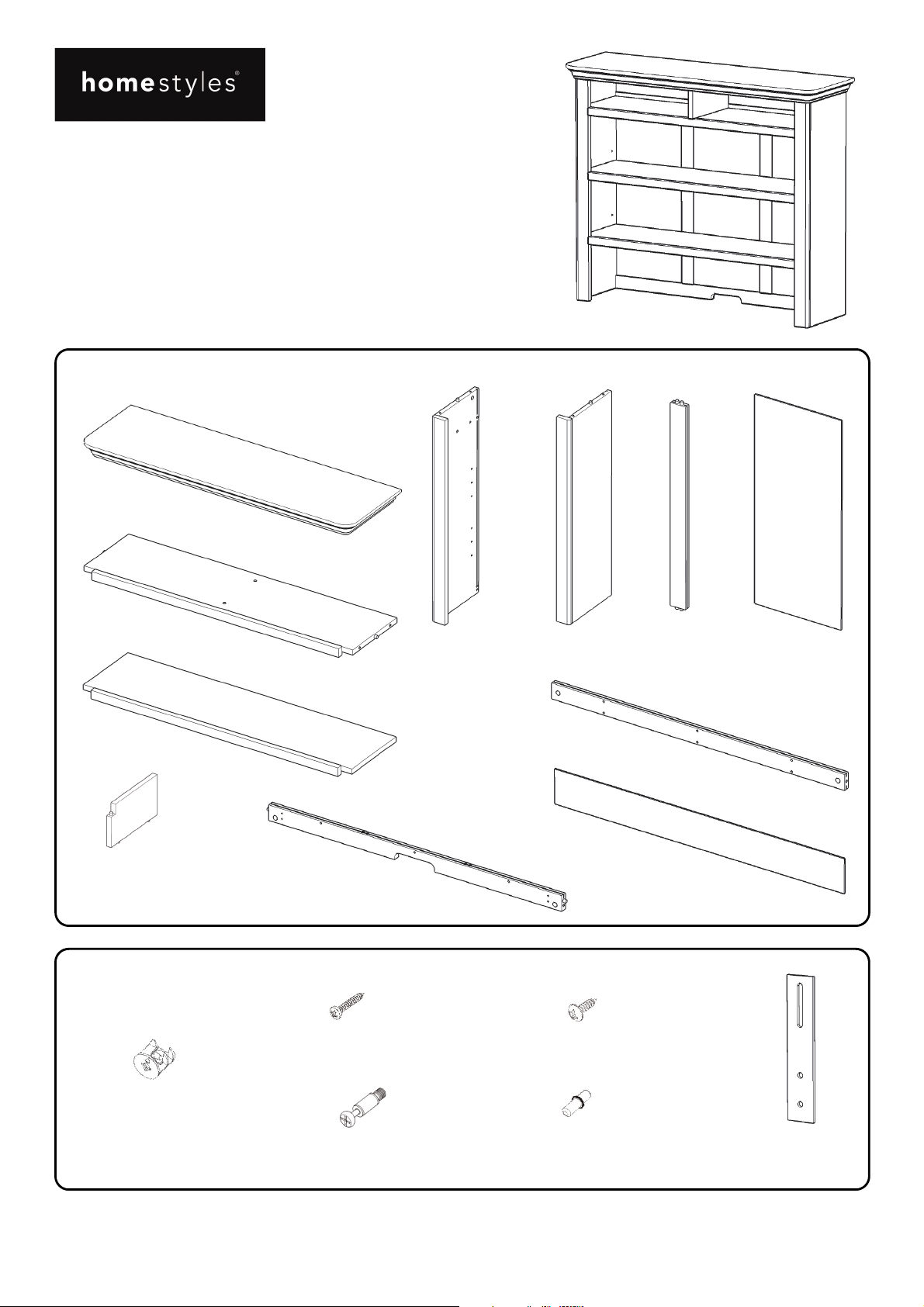
Hutch
IMPORTANT
Carefully remove all the parts from the carton and
place them individually on a soft cloth to prevent
scratches or other damage.
Carefully and strictly follow these assembly instructions
to ensure a completed product as designed.
Do not use power tools above 8 volts to assemble.
Part List
A.
To p
1 pc.
B.
Shelf
1 pc.
C.
Shelf
2 pcs.
H.
Divider
1 pc.
Hardware List
I.
Back Rail
1 pc.
M3.5x16
Wood Screw
9 pcs. (+1 extra)
D.
Side Panel
1 pc.
E.
Side Panel
1 pc.
J.
Back Rail
1 pc.
K.
Back Panel
1 pc.
M4x13
Wood Screw for Bracket
8 pcs. (+1 extra)
F.
Back Upright
2 pcs.
G.
Back Panel
3 pcs.
Cam Lock
12 pcs.(+1 extra)
Cam Lock Screw
12 pcs.(+1 extra)
Tool(s) required for assembly: Phillips screwdriver, Drill (8 volts or less), 3/8” Drill Bit
Adjustable Pin
8 pcs. (+1 extra)
Home Styles Customer Service: www.homestyles-furniture.com,
servicedesk@homestyles-furniture.com,
888-680-7460, 877-831-0319
Bracket
2 pcs.
Page 2
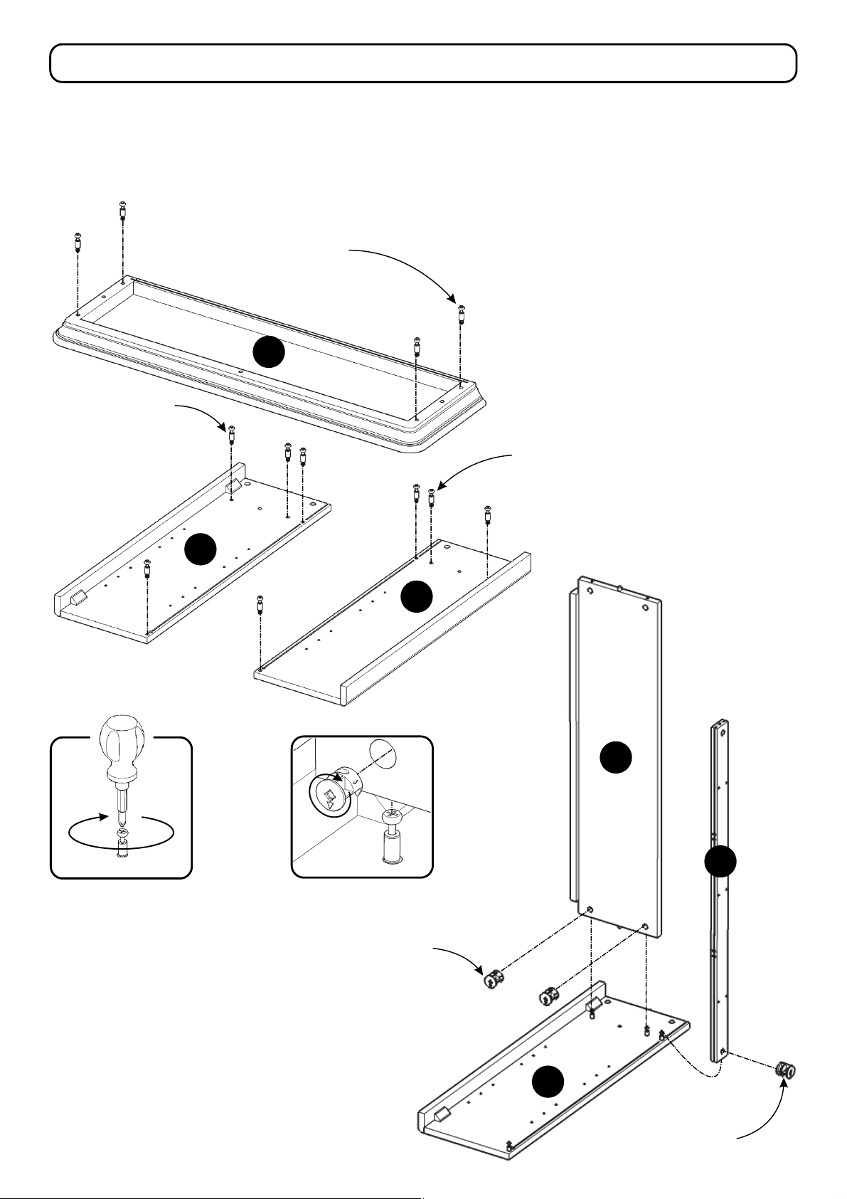
Assembly Instructions 2/6
IMPORTANT
Use a soft cloth between these parts and the floor.
Do not use power tools above 8 volts to assemble.
Do not tighten all the bolts until each part is properly assembled.
The unit must be level to work properly. Use the included adjustable levelers to level.
Cam Lock Screw
STEP 1
Cam Lock Screw
D
A
Insert Cam Lock Screws into
pre-drilled holes in Top (A), and
Side Panels (D), (E), then tighten.
(See Figure 1)
Cam Lock Screw
E
B
Figure 1
STEP 2
Attach Shelf (B) to Side Panel (D)
with Cam Locks. (See Figure 2)
Attach Back Rail (J) to unit with
Cam Lock.
J
Figure 2
Cam Lock
D
Cam Lock
Page 3

STEP 3
Slide Back Panel (G) into place.
Attach Back Upright (F) to unit.
Assembly Instructions 3/6
Slide Back Panel (G) into place.
Attach Back Upright (F) to unit.
Attach Back Rail (I) to unit with Cam Lock.
Slide Back Panel (G) into place.
E
G
F
G
F
G
I
Cam Lock
Cam Lock
STEP 4
Attach Side Panel (E) to unit with Cam Locks.
Page 4

Assembly Instructions 4/6
A
H
STEP 5
Slide Back Panel (K) into place.
Attach Divider (H) to unit.
K
Attach Top (A) to unit with Cam Locks.
Cam Lock
STEP 6
Insert Adjustable Pins into
side panels at desired level.
Place Shelves (C) into position.
C
C
Adjustable Pin
Page 5

Assembly Instructions 5/6
STEP 7
Insert Wood Screws into pre-drilled holes
of unit, then tighten.
Wood Screw
Attach Hutch to Buffet with Brackets
by inserting Wood Screws for Bracket
into pre-drilled holes, then tighten.
(See Figure 3)
Bracket
Wood Screw
for Bracket
Figure 3
STEP 8
Page 6

Assembly Instructions 6/6
IMPORTANT
To help reduce the risk of the unit tipping over, the Tip-over Restraint must be installed following these instructions exactly.
STEP 9
Place unit at desired location.
3/8” wall hole
Drill a 3/8” hole in wall in-line with
Pre-drilled hole at top of unit.
Move unit.
Insert Anchor into the wall hole
and attach Bracket with Wall Screw.
Attach Bracket at pre-drilled hole
at top of unit with Wood Screw.
Move unit back into place.
Slide Tip-over Restraint through
Bracket on wall and Bracket on unit.
(See Figure 4)
Put tie end of Tip-over Restraint into lock
end of Tip-over Restraint and pull until tight.
Anchor in wall
Tie end
Lock end
Bracket at
top of unit
Tip-over
Restraint
Bracket
on wall
Wall Screw
Figure 4
Pre-drilled hole
at top of unit
Wood Screw
Hardware List
Anchor
1 pc. (+1 extra)
Bracket
2 pcs. (+1 extra)
Tip-over Restraint
1 pc. (+1 extra)
Drill 3/8” hole in wall
M3.5x40
Wall Screw
1 pc. (+1 extra)
Top of unit
M3.5x16
Wood Screw
1 pc. (+1 extra)
 Loading...