

HomeSeer HS-FLS100+ User Manual
HS-FLS100+ | Z-Wave Plus Floodlight Sensor
Be sure to visit our website for the most up-to-date information about this product:
https://homeseer.com/support-home/
Overview
The HS-FLS100+ is a PIR module that’s designed to retrofit onto exist ing outdoor
floodlights. It features a PIR sensor to detect motion through movement of heat
sources and a LUX sens or for determining brightness of its surroundings. It is
equipped with Z-Wave Plus wireless com munication capability that will convert an
ordinary motion-activated floodlight into a smart home device.
Conventional Floodlight Mode
HS-FLS100+ can be used as a conv ention al m otion-activated floodlight sensor to
power floodlights when motion is sensed during dark hours. Controls are provided
for manual adjustment of LUX sensitivity and floodlight ON times.
Smart Floodlight Mode
When added to a smart ho me system, HS-FLS100+ will s en d Z -Wave commands
to the smart hub or home control ler when motion is sensed and when the LUX
level changes. Likewise, the smart hub or home controller can send Z-Wave
commands back to the HS -FLS100+ to turn floo dlights ON and OFF. This added
functionality provides a very high level of flexibility not typically available in
conventional motion-activated floodlights.
Smart Sensor Mode
HS-FLS100+ can be installed and used simply as a n outdoor motion and LUX
sensor. Floodlight functionality is not required. This provides some interesting
security and smart home possibilities!
S2 Security
This product supports the S2 security protoco l that uses encrypted Z-Wave Plu s
messages to communicate to o ther security-enabled Z-Wave Plus prod ucts. A
security-enabled Z-Wave Plus controller must be used in order to f ully utilize the
security features of this product.
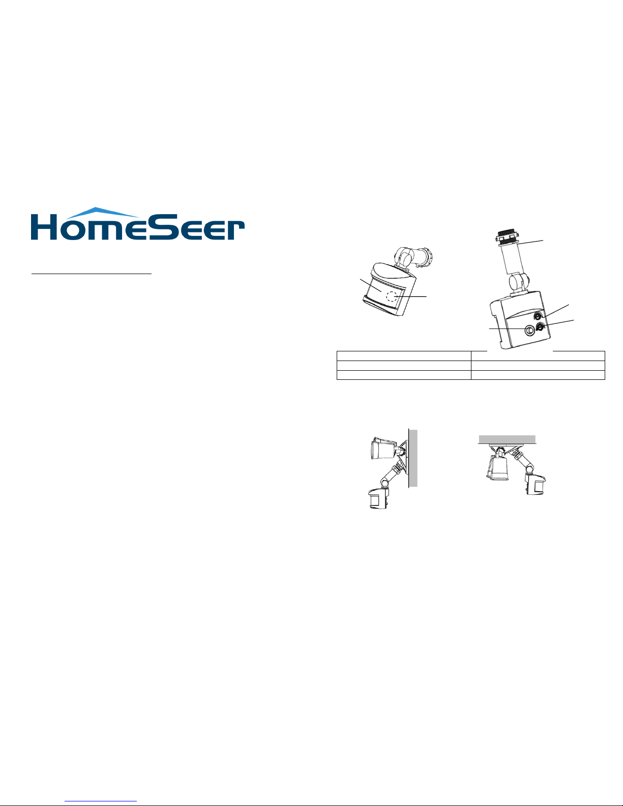
Product Overview
PIR Lens
Lux knob
LED indicator (hidden behind lens)
Timer Knob
Link button
Threaded arm
Below diagram show a typical assembly of HS-FLS100+ on a floodlight fixture (not
provided).
(Wall mount) (Under Eave mounting)
Note: Please read this entire instruction manual before you start the installation.
IMPORTANT
Installation must be performed by skilled technicians who are informed
about the standards and technical requirements of the appliance and its
proper installation.
Check your local codes as they apply to your situation. If the house wiring is of
aluminum, consult with an electrician about proper wiri ng m ethods .
Before proceeding with the installation, TURN OFF THE POWER TO THE
LIGHTING CIRCUIT AT THE CIRCUIT BREAKER OR FUSE BOX TO AVOID
ELECTRICAL SHOCK.
SAFETY PRECAUTION
DO NOT install when it is raining.
Isolate the power supply before installation.
Ensure that local Wiring and Building regulations are complied with.
The unit is supplied with a pre-wired supply cable this must be used and must
not be removed.
Total lighting load to HS-FLS100+ not exceed:
- 300W incandescent @ AC120V
- 100W LED @ AC120V with 0.8 pF Driver
Installation & Wiring instructions
Note: As with any outdoor installation work it is always recommended to start early
during the day.
WARNING: TURN OFF POWER BY REMOVING POWER FUSE OR TURNING
OFF CIRCUIT BREAKER BEFORE INSTALLATION.
Taking down the existing floodlight
1. With mains supply turned off, if possib le remove the lamps from the bulb
holders of the existing floodlight to avoid any damage during the installation.
2. Carefully detach the floodlight from the wall by removing its mounting screws.
Keep all parts for reuse later, including any rubber rings. Take note the
direction of the rubber gasket as it needs to be reassembled later in the same
way.
3. Disconnect the mains wire from the floodlight by untwisting the wire nuts.
4. When done, place the floodlight on a table to prepare for wiring the
HS-FLS100+.
Removing old motion sensor
(Skip this section if the existing floodlight has no motion sensor)
5. Locate the wires coming fr om the old motion sensor, usually colored black,
white and red.
6. Disconnect the wires of the motion sensor by cutting it if necessary.
7. Remove the old motion sensor from the mounting base by twisting its
threaded arm counter clockwise.
Yellow/Green
Black
White
Earth
GASKET
Live
Neutral
Cut here
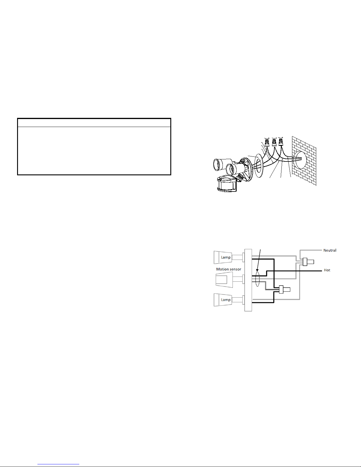
Wiring up the HS-FLS100+
8. Screw the threaded arm of HS-FLS100+ into t he mounting base. For typical
wall installation, HS-FLS100+ should be located at the bottom of the mounting
base.
9. Connect up the wiring as in the diagram below, using wire nuts to j oin the
wires. If replacing an old motion sensor, simply follow the same wiring color as
the old motion sensor.
10. Route the power leads through the rubber gasket to g et r ea d y for wall mount.
Ensure the rubber gasket is facing the same direction as it was before.
11. When completed, turn t he k nobs of Time-Off on the unit to “T” mark, and tur n
the knob of Lux on the unit to the “
” mark.
Assembling back the floodlight
12. Connect back the mains wire as b efor e. Tuck the wire nuts and excess c able
neatly inside the junction box.
13. Screw the lighting floodlight back into position using its mounting screws.
Place the rubber rings back into their positions.
14. Insert the lamps removed earlier back into the bulb holders, adjust the lamp
direction if necessary.
15. Reinstate the power supp ly to the floodligh t and switch on the wall s witch, if
installed. The floodlig ht will turn on for around 5 seconds for warm up and
then turn off. It is now in ‘Test Mode’.
Walk Test
The user can perform a walk test to ensure the PIR detector’s range falls within
the desired area of coverage.
1. Walk through its PIR De tector coverage area. The fl oodlight turns on when
you move and turns off after approxim ately 5 seconds. Wait for the floodligh t
to turn off before the next test.
2. When you are satisfied with the coverage area you c an now s et the desired
Time period and Lux level.
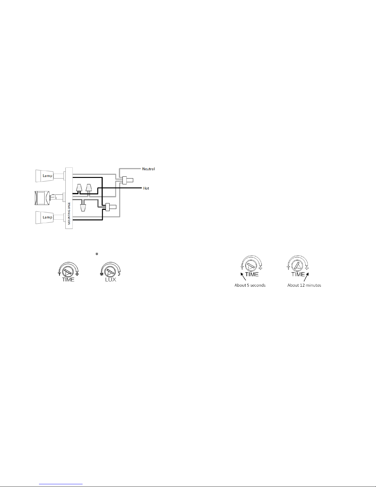
Time and Lux adjustment
You can set desired Time period and Lux level through;
(i) the Z-Wave controller after connecting to a Z-Wave network (see next section)
or,
(ii) manually adjusting the knobs on the unit if not connected to a Z-Wave
network. The following section describes the steps for manual setting.
(1) Time adjustment
Time-off knob controls ho w long the floodlight will stay on after the m otion is
detected. Turning the knob to wards the + s ign increases the time (up t o about
12 minutes ) or towards the T decreases it (down to about 8 seconds). The
recommended setting is around midpoint of the scale giving approxim ately 5
minutes.
(2) Lux level adjustment
The LUX knob sets the threshold of am bient brightness level that will activate
the motion sensor. The knob can be adjusted between T (always trigger
regardless of light level) and the m oon symbol (trigger onl y when dark). The
adjustable Lux range is about 30 - 200 Lux.
 Loading...