

HomeScenario HSC000000A1 User Manual
2009
HSC-300
HSC-300
HSC-200
HSC-200
HSC-100
HSC-100
HMP-100
HMP-100
HMS-100;HSC-50
HMS-100
Advanced Scenario Hub/Music Server
Server
HomeScenario
User Manual
User Manual
YC Wang
Home Scenario Inc
2008/7/31

Chapter 1 What you can do
With HSC-200, you can
z Distribute audio to the whole house(HSC-200 only).
z Control the lights, power adaptor or other devices according to the pre-defined
schedule or from PC, PDA, Microsoft Mobile phone, iPhone or any devices with
flash-lite player.
z Create scenarios which will control your lights, power switches or IRDA
compatible devices according to the user-defined rules. Users can change the
rules from the built-in web interface.
z Create user interface for the LCD panel, TV or other devices.
All of these are included in the HSC-200. No extra software or equipment is required
to build your own home automation project.

Chapter 2 Getting Started
The HSC-200 can be accessed by using any flash-enabled devices, such as touch
screen or your personal computer. Many smart phones, such as iPhone/HTC
dream/magic/hero, provide enough capability to access the HSC-200. Please refer
to our website for all tested equipments. If your device is not in the list, it can be still
supported if it has flash-lite player or browser. It is welcome to post your experience in
our custom forum so that we can put it into the supported list.
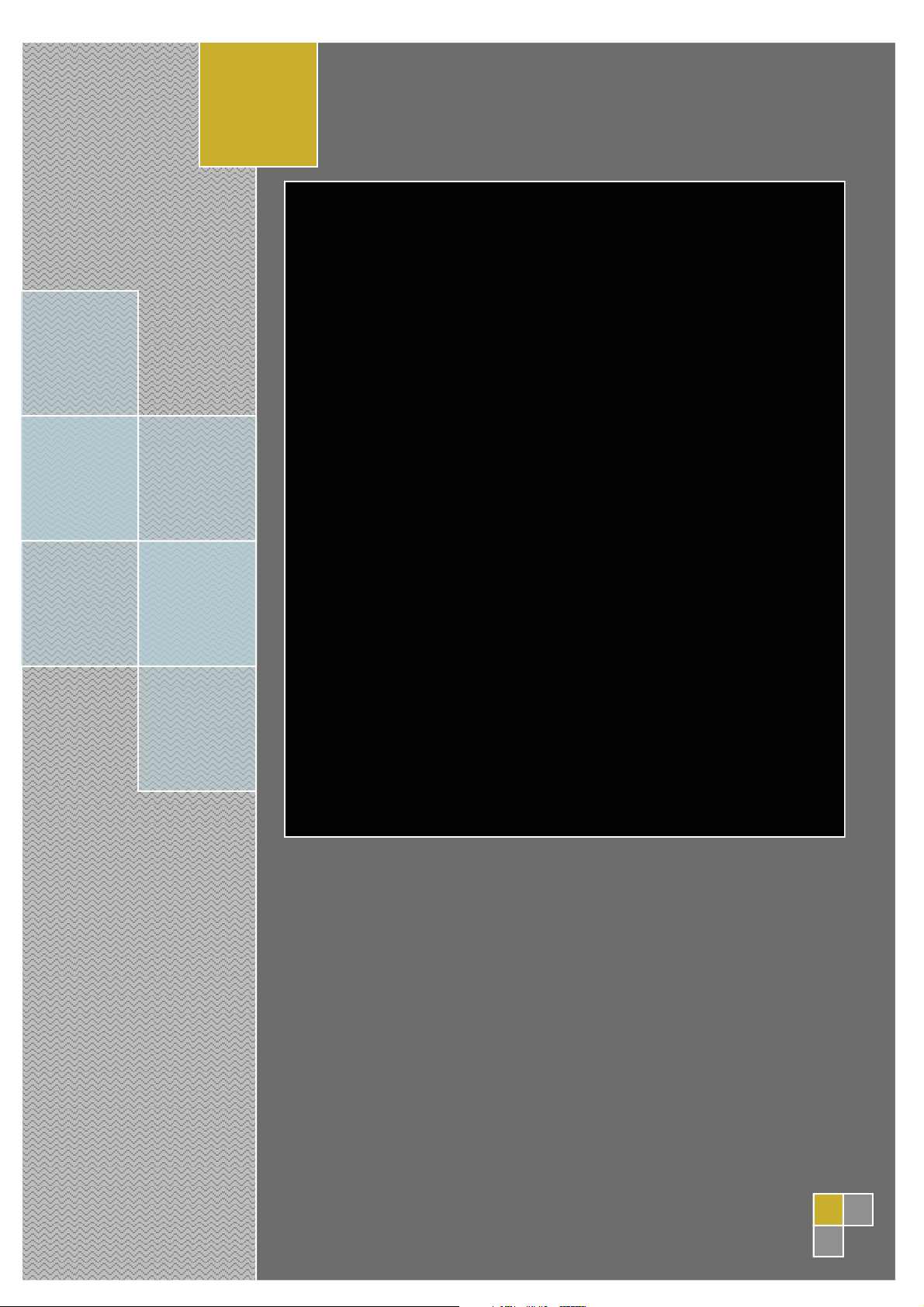
If you are using personal computer, PDA or smart phone to access the HSC-200, you
need to input the ID and password that is usually printed in the bottom of the device
by the installer.
The HSC-200 can be served as audio transmitter out of the box. It will broadcast the
audio from the input 1 and USB to the network if the input is available. The HSC-200
will not send any data unless it detects audio data in the input. Therefore, it will stop
sending data if the input is muted.
In order to enable the light and home theater control, we must enter the web interface
to configure the system. The HSC-200 will use DHCP to acquire the IP address. If
there is no DHCP server available in the network, the default IP address is
192.168.10.100.
Usually, under the environment with DHCP, the HSC-200 will broadcast itself by using
UPnP protocol. The DHCP Host in the XP or Vista can detect it and display it in the
network controller. Double click the icon will enter the configuration page. The
configuration system of the HSC-200 use flash. Therefore, we must install the flash
player in the PC. If the flash player is not available, it will ask users to install one
automatically.
After we enter the configuration page, we can include lights, AV equipments, power
adaptors and other devices in your house. Please refer to the scenario definition for
the details.
In addition, you can create your own home automation user interface by using the
page composer, which is part of the HSC-200 UI. The page composer can help you to
create pages that are used to control and show the status of your devices. Please
refer to the page composer chapter for the details.
2.1 Enable installer account
Usually, the installer account is disabled for safety issue. If we want to allow install to
check the condition of the HSC-200 temporarily, please follow the below procedure to
enable the installer account. Please remember to follow the same procedure to
disable the installer account.

The default Username and Password are both installer. Installer should change it to
the value which is only known by the installer.
1. Touch the setup button.
2. Touch the button 1.
3. Touch the button 2.
4. Touch the button 3.
5. You will hear the beep once.

Chapter 3 Device management
HSC-200/300 can support variant types of devices. Each device has different setup
procedure and options. It will be tremendous job for users to understand the details of
them individually. Fortunate, the device manager plays an important role here to help
users to understand each device in the user-friendly interface.
No matter we use Z-wave/O-net/Zigbee/RS232/three wire/four wire devices. The
setup procedure is roughly the same. The device wizard will remind users to do the
right job step by step.
3.1 Device association procedure
Device manager divide the association procedure into three steps.
z Select device profile
z Activate the device into learning mode
z Notify HSC200 the device has been learned.
For the first step, HSC-200 uses the barcode in the devices to recognize the model of
the device. It will look up the internal database to decide if we can support this device
or not. If the barcode can not be supported, an UI will be used to remind users.
Once the barcode is input correctly, the HSC-200 will show setup pages for each
device. Users can follow the instruction in this page to figure out how to make the
device into the learning mode.

For bi-directional devices, such as Z-wave or ZigBee, the third steps will be done
automatically. For others, the UI will explain to the users how to verify the device has
been learned or not.
3.2 Add new device
Except the built-in audio transmitter, all devices need to be added before they can be
controlled by the HSC-200. For the security reason, we need to press a physical
button in the devices in order to put them into the association mode. Devices under
the association mode will allow the HSC-200 to build association. In this way, we will
not learn the device in your neighborhood by accident.
In order to associate a node, we need to follow the below steps.
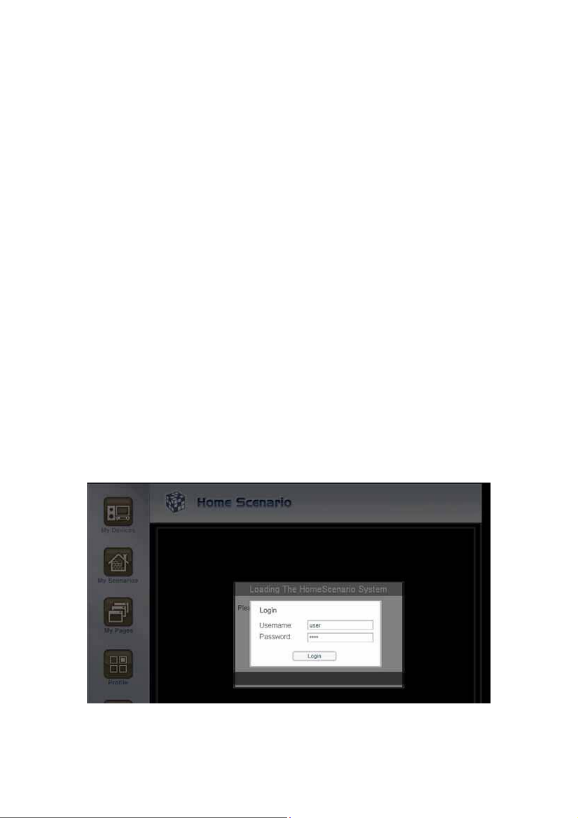
1. Enter the node viewer
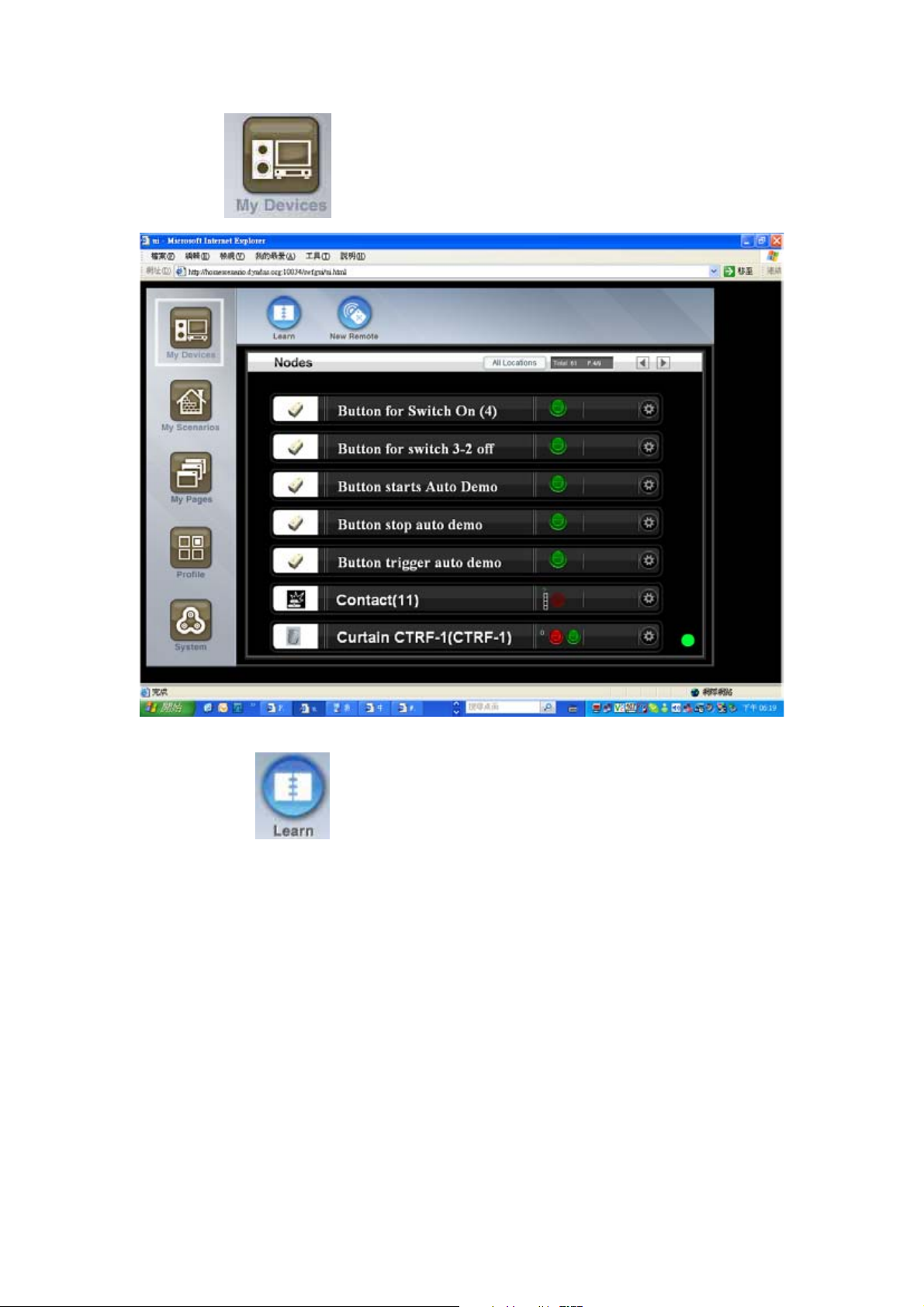
2. Select the ‘Learn’ icon
3. Enter the barcode of the device
4. Press the association button in the device.
5. Confirm the association.
Please note that the step 4 must be done in the device. After the step 3, the UI will tell
us the look and feel of the device and mark the location of the association button
according to the barcode entered in step 3.
3.2.1 Press to enter the device panel
3.2.2 Select the
icon
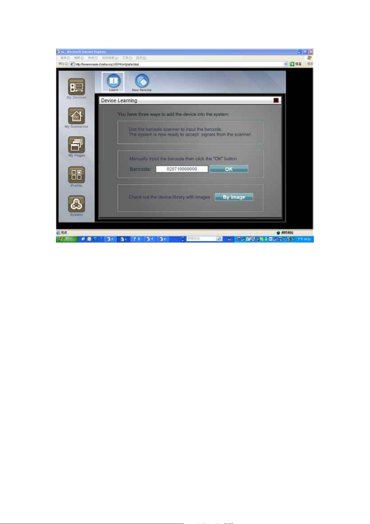
3.2.3 Enter the barcode of the device
All devices have a barcode in the physical unit. We can use the barcode scanner to
input the barcode to the HSC-200. In the step 3, the following UI will be displayed,
The barcode scanner will fill the barcode field and then enter the step 4 automatically
if the barcode is correct. Without the HSS-100, we can input the barcode manually.
The human-readable barcode is located in the bottom the barcode stick. It includes 11
digits. Please input all of them into the barcode field. If the input is correct, the ‘Start
association’ button will be enabled. Please click it to start the association procedure.
The barcode number can be input manually if the barcode scanner is not available.
In addition, we can select the type of devices to add. Please click the ‘By Image’
button. The photo and model name of each device will be listed as the below picture.
3.2.4 Press association button in the device
According to the barcode input in step 3, the UI will display the look and feel of the
physical device and mark the location of the association button. Please follow the
instruction in the screen to associate the devices.
If your device does not match the graphic in the UI, please check if you input the right
barcode. Please contact your local technology support or the official support forum to
verify it. HSC-200 may not support devices from other vendors. Please make sure
your devices are supported.
3.2.5 Confirm the association
Most devices will blink their LED when it is associated with HSC-200 successfully. For
ಮ
ಯ
uni-directional devices, we need to press the confirm button in the screen to notify the
HSC-200 that device has been added successfully so that the HSC-200 will leave the
learning mode.
For bi-directional devices, such as Z-wave, this step is done automatically since it can
acquire the status of the devices via RF-link. Please refer to the setup screen of the
devices to know if we need to do this step or not.
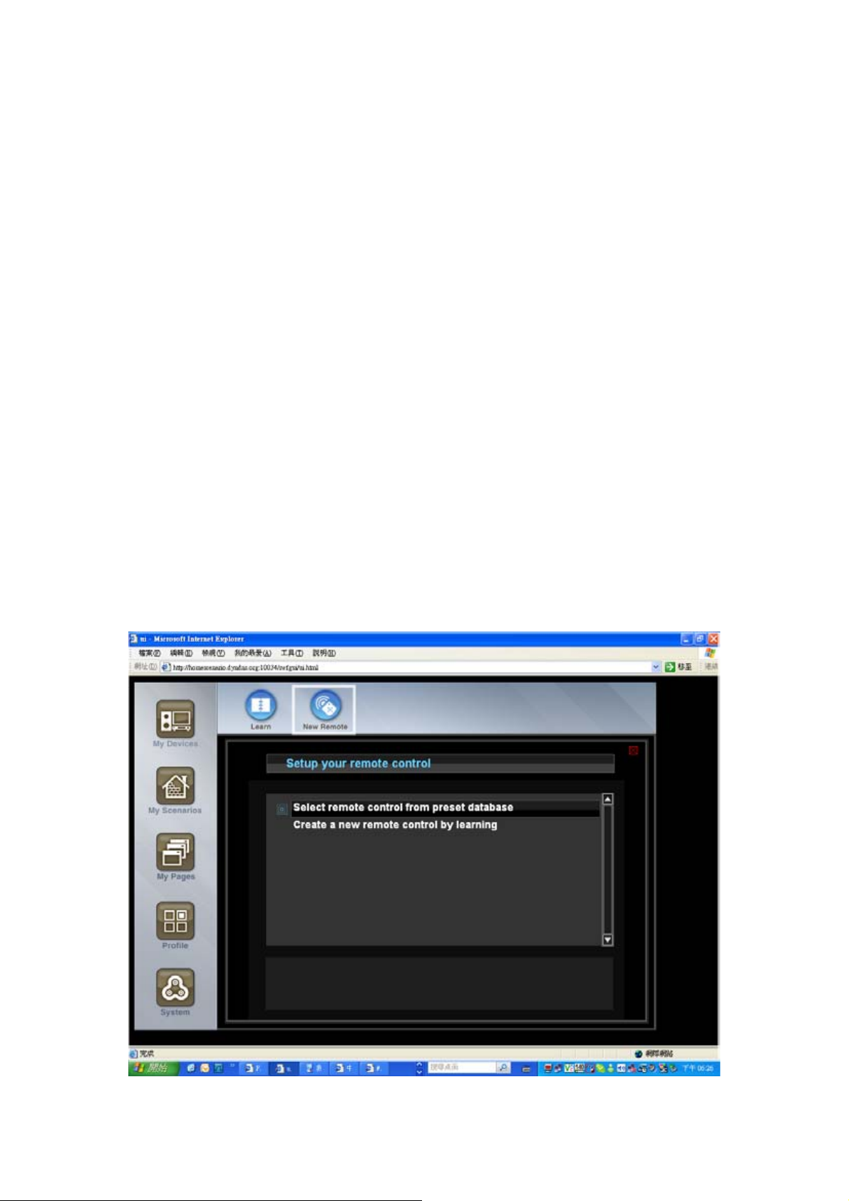
3.3 Add IR device
In order to add a IR transmitter device, we need to choice the “new remote” icon in the
top of the screen. An IRDA wizard will be used to help us to configure an IR device.
3.3.1 Select
New Remote
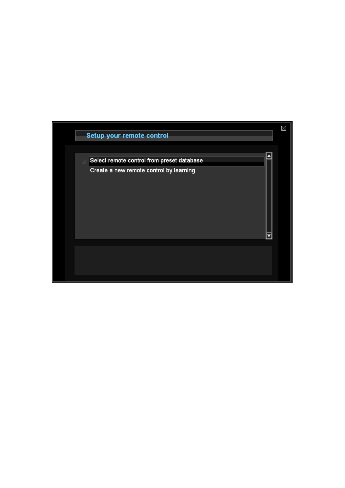
3.3.2 Add IR device from the built-in database
The HSC has built-in database, which allows us to select a IR device by using device
type, vendor or model name.
3.3.3 Add IR device by using IR learning
HSC can built-in an IR device by IR recording. The built-in IR recorder can capture the
IR signal of the original IR transmitter.
The HSC provides the capability to mix the builtin database with a couple of learned
keys. We can choice one remote from the internal database and change some of keys
with IR learning. Typically, there are a couple of keys in the builtin database, which
does not match the real device since the model name is not 100% match. For
example, when we choice a TV, the built-in database is for old models so that most
keys works fine except the PVR function which is available in the new model only. In
this case, we can use IR learning to add these extra keys.
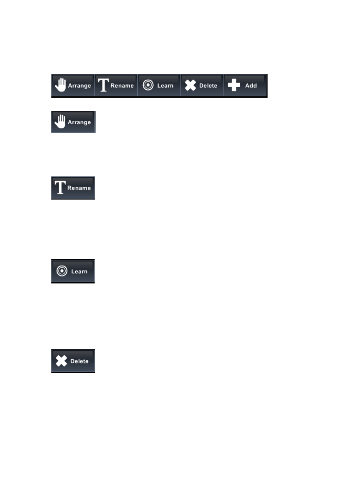
3.3.4 IR customization
Move the location of the keys. The location is only for presentation only. It won’t
chanfge the key at all.
Change the name of the key. Please click this icon and then the cursor will change to
rename mode. We can click any key and then the key will become edit mode.
This is used to change a key to be learning mode. Please notice that this action can
not be reversed. Once it become learning key, it can not be recovered to be key in the
database any more. If we still want to use the database key, we need to create a new
remote from scratch again.
Delete an IR key.
Add a new key. Initially, the key is not associated to any IR signal. We need to use
“Learn” function to associate an IR signal to a new key.
Use the IR remote wizard to select another remote. Please be warned that all setting
will be dropped after we change the remote.
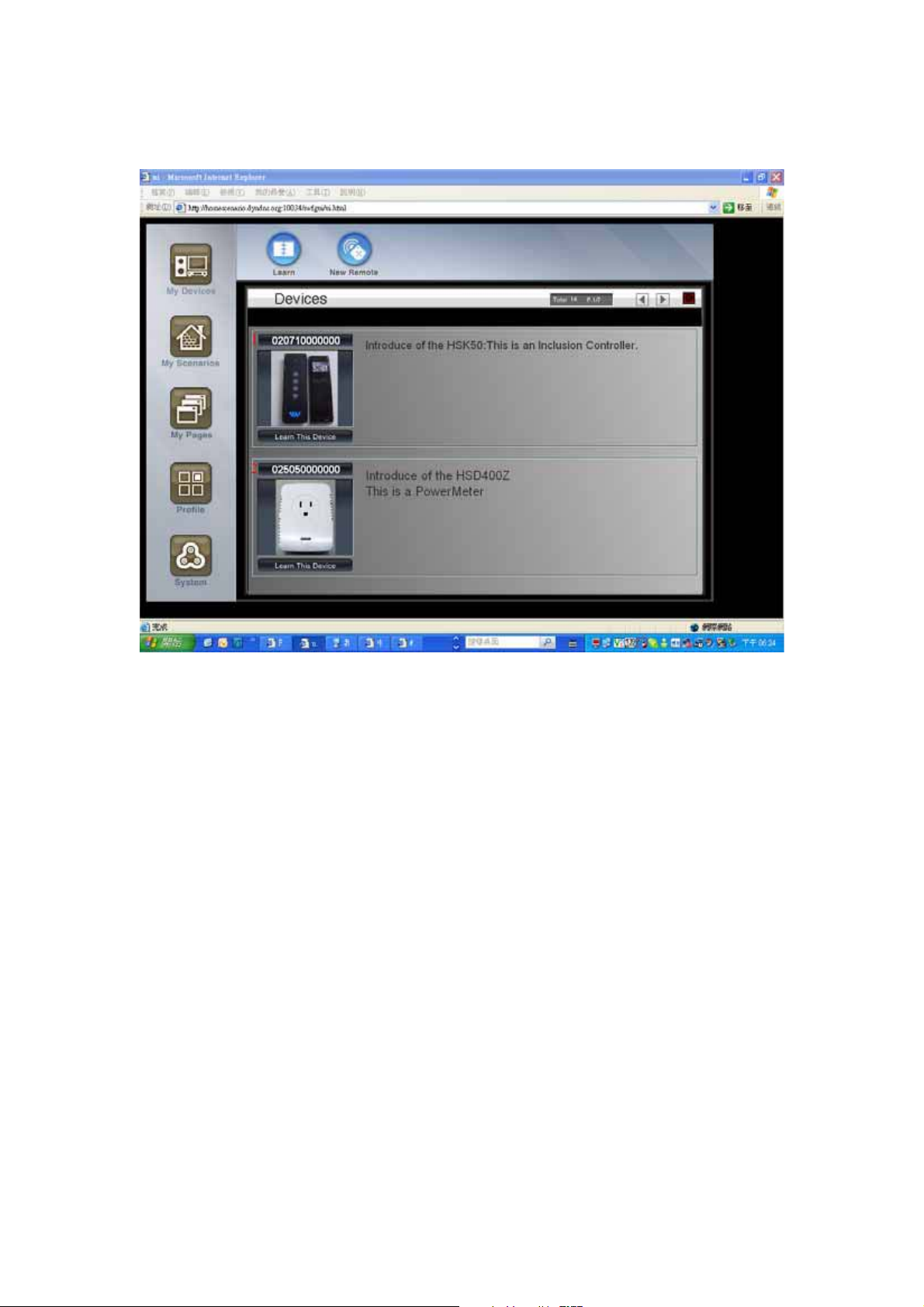
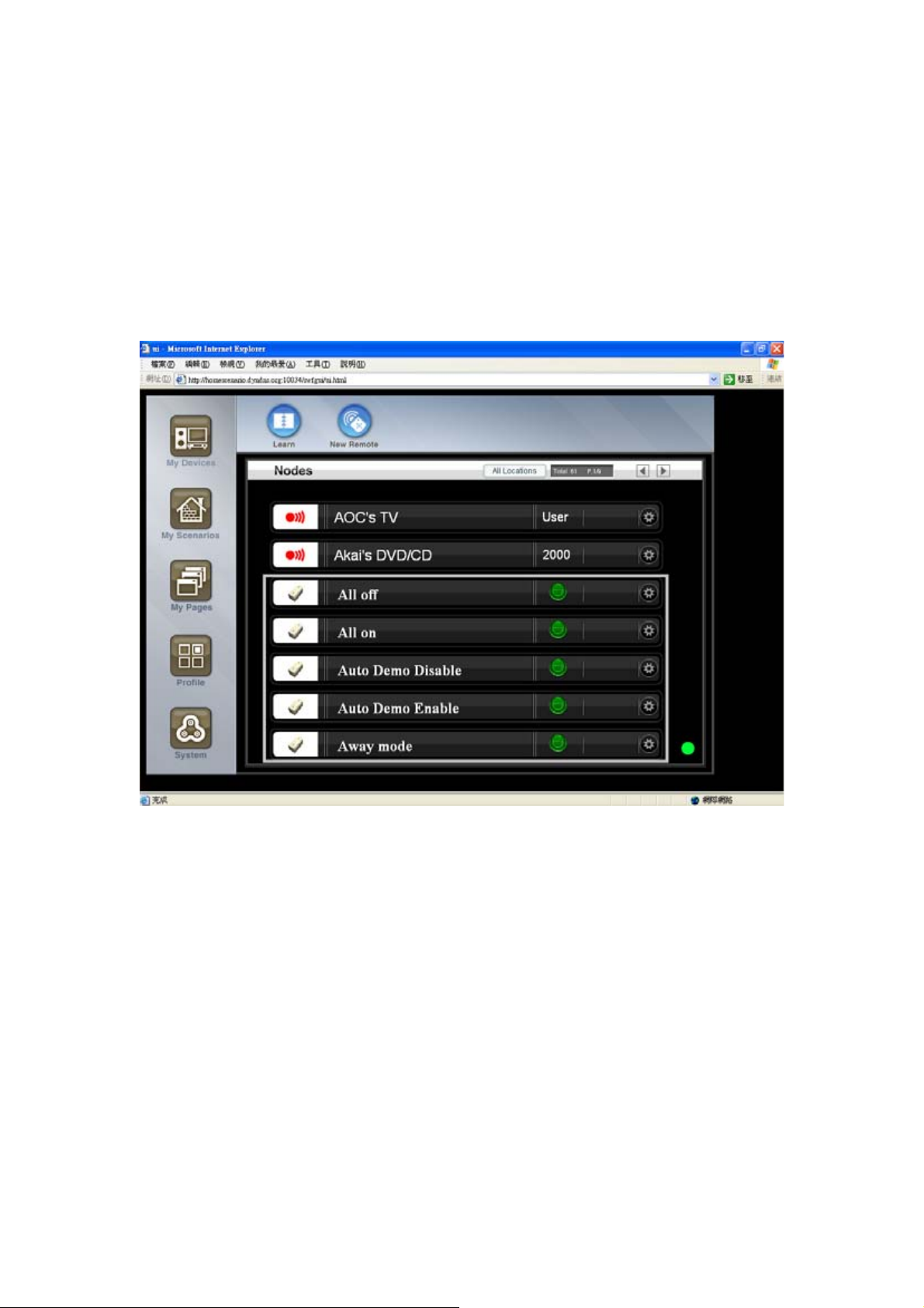
3.4 Browse device
After the device is added, it will be listed in the node viewer. The node viewer is
available under the ‘My Devices’ section.
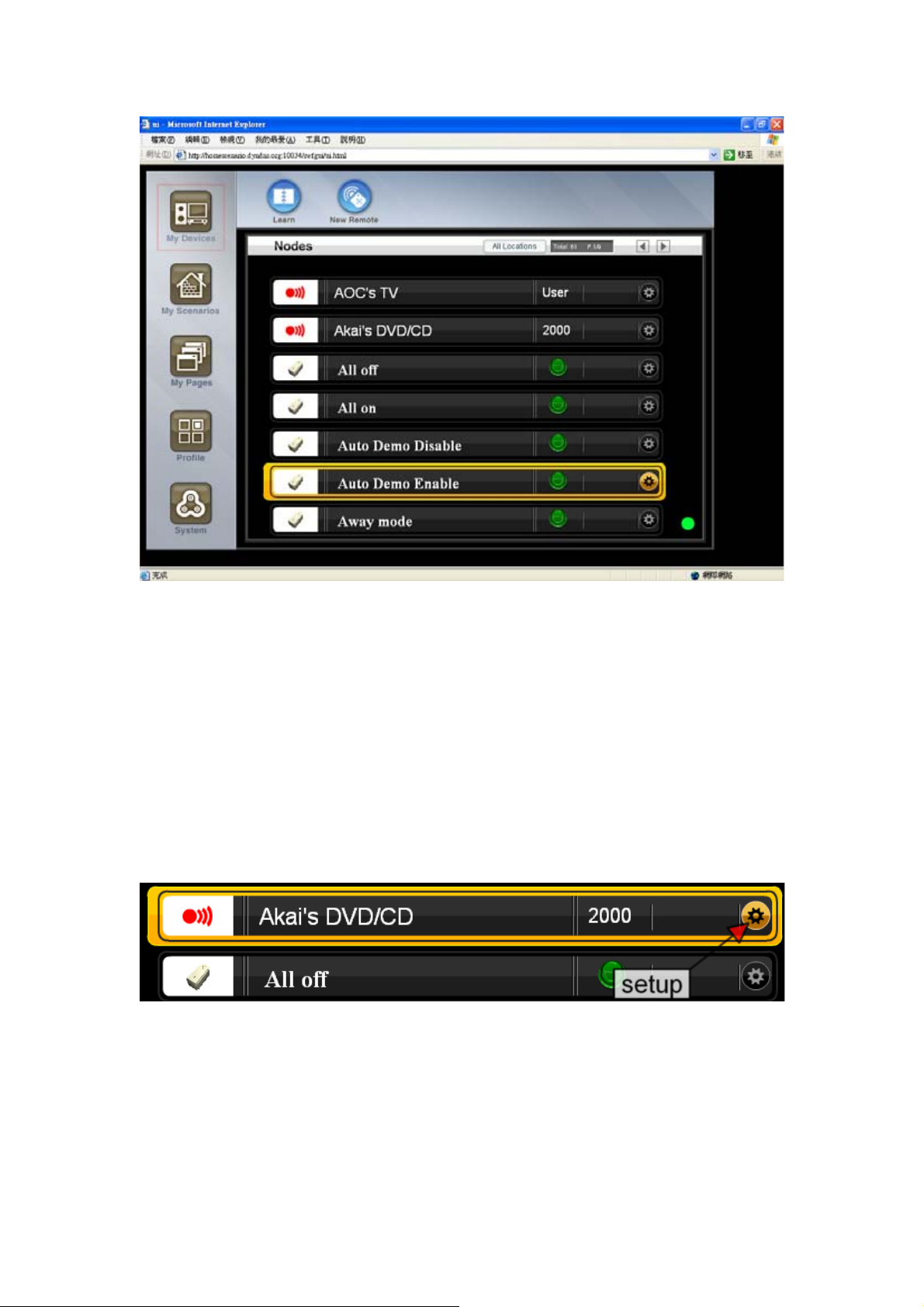
Each device is listed as a single line. Please look at the picture. There is an icon in the
right side to invoke the preview and setting view of the device.
3.4.1 Setting mode
Some devices, such as light and power switch, have online widget which can operate
it from the device panel directly. Most devices can not be controlled without entering
the setting view.
3.4.2 UI device
In addition to the physical devices, the device panel will list the UI devices as well. The
UI device is created to call actions of the scenarios so that we can execute multiple
operations among all devices. For example, we can turn on a group of lights by click
the UI button. Please refer to the scenario chapter for the details of the UI devices.
Since the UI device is listed in the device manual, users can execute scenario actions
by clicking the UI widget in the device panel. For example, the following UI switch is
named as ‘master room light control’ and it can be used to turn on/off all lights in the
master room.
The device panel provide very primitive user interface to control the devices. In order
to build a more user friendly environment, the HSC-200 provides two functions
z We can use the scenario editor to create very complex scenario to execute
actions in certain time or conditions. The Scenario Editor provides a user friendly
CAD-like interface to group devices and create complex logic without writing any
program.
z We can use the page composer to create final user page which is more user
friendly than the device panel. The page composer can create as many pages as
possible by using built-in widgets to collect information from the devices and send
control command to them. It can work with the scenario editor to build very
powerful scenarios or macros to control all devices.
Before we introduction the scenario editor and the page composer, let’s take a tour of
all functions provided in the HSC-200. If you are eager to understand the most decent
building system of the Home Scenario Builder, please skip the following chapters and
go to chapter xxx for it.
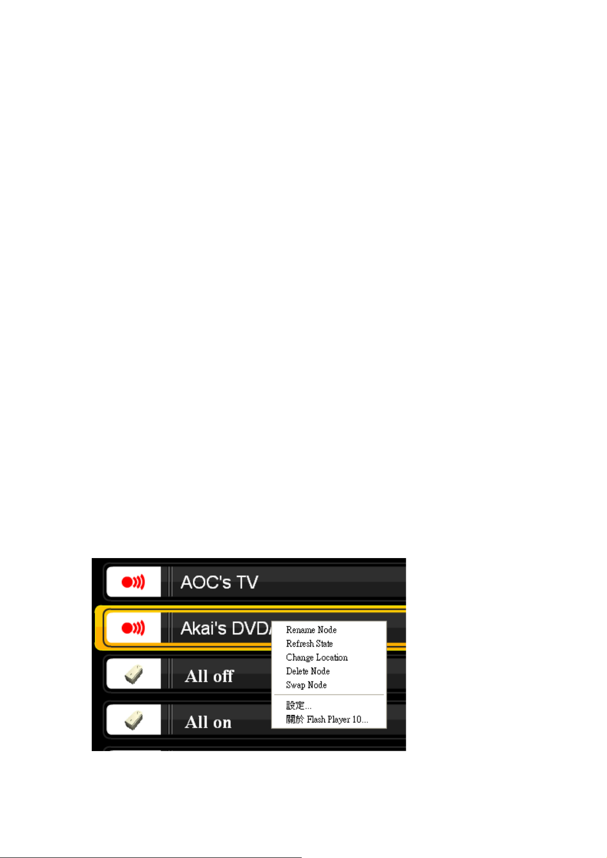
3.5 Context menu
In the node viewer, each device has context menu with the following items.
z Rename Node
z Refresh state
z Delete Node
z Change Location
z Swap Node
3.5.1 Rename Node
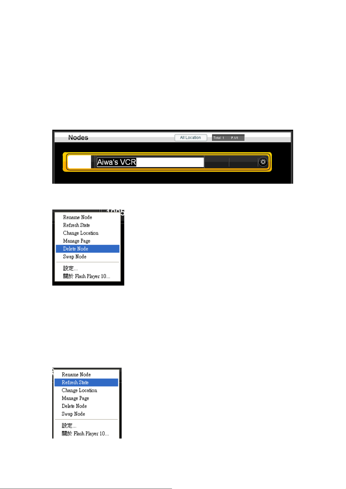
This function will show an inline text editor to change the name of the device. Since
the node viewer will sort the device by name, change the name of the device will
invoke a screen refresh and you may not be on top of the original node after the
rename.
In the end of text editing, press an enter will close the inline text editor and show the
original node viewer again.
3.5.2 Delete Node
This function will delete the current node form the node viewer. Please notice that it
may not delete the setting in the underline network in the same time. Please refer to
the chapter of devices to find how to delete device from their network.
3.5.3 Refresh state
This function will try to get the latest state of the selected device. If we suspect that
the display status is not up-to-date, we can use this function to fetch the current status
of it.
This is useful for some devices which will not report its status when it is change
manually. For example, the Z-wave switch will not report its state change when we
use the button on the device to change it from on to off or from off to on.
This feature works for bi-directional devices, such as IP or Z-wave devices only. For
the Z-wave device, it must be always-on devices or FLIRS.
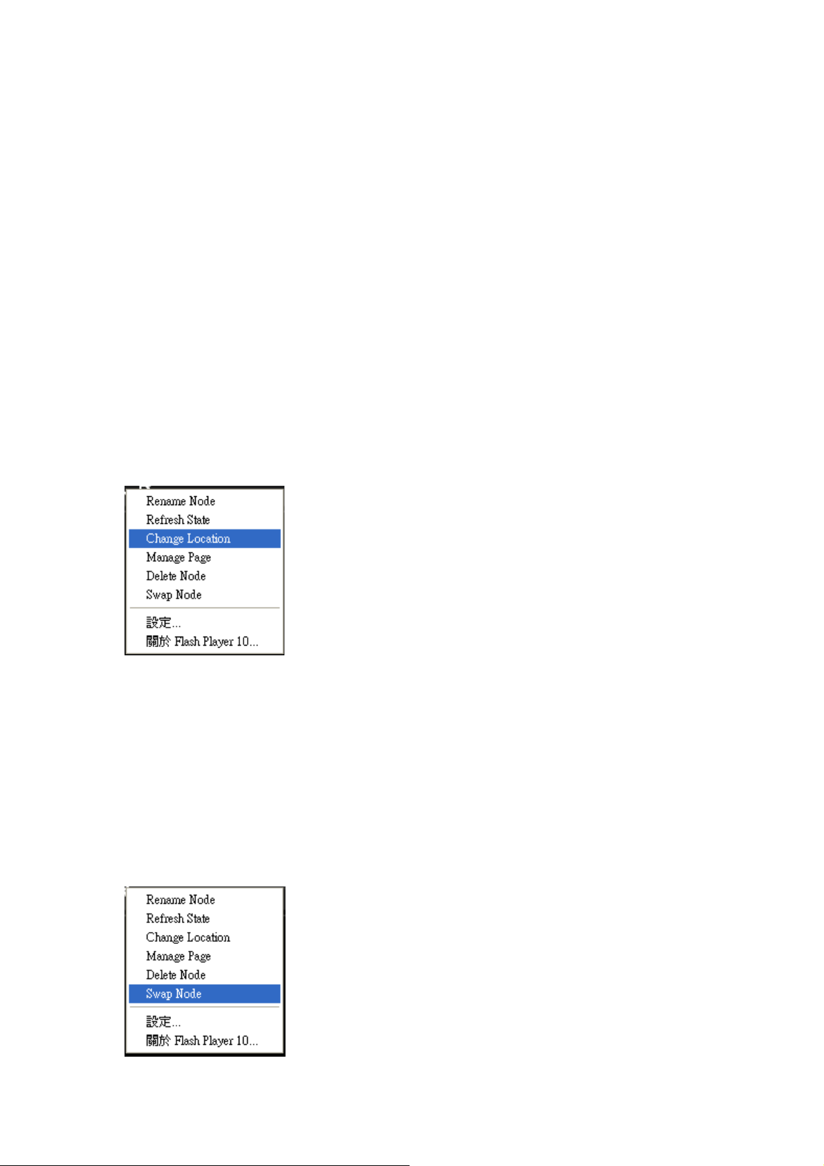
3.5.4 Change Location
Each node has a location property. This property can be used to filter devices from
the location button.
This function will invoke a inline text editor. Please press ‘Enter’ in the end of editing to
confirm the input.
3.5.5 Swap Node
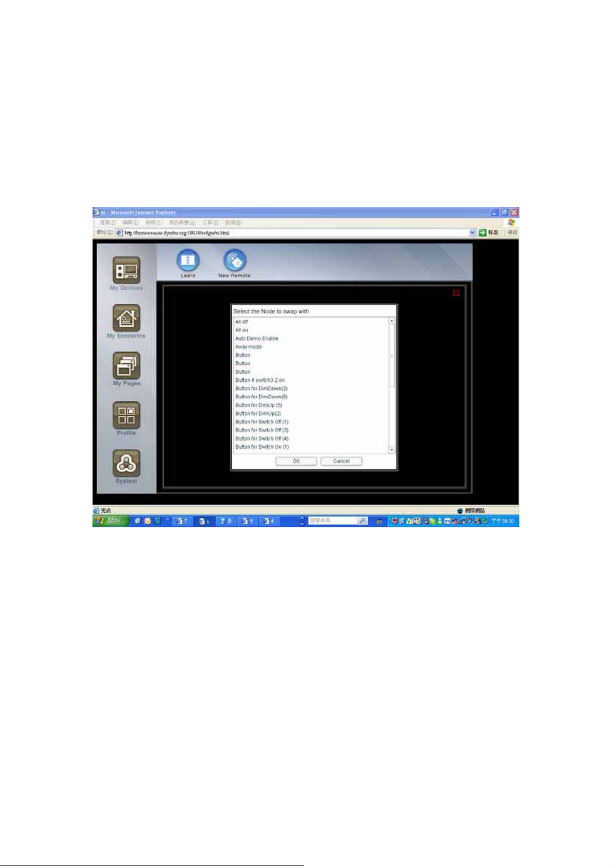
If a device is broken, we may want to add a new device to replace it. However, it will
be very inconvenient if we need to replace each node in all scenarios. Therefore, the
node viewer provides the Swap Node function, which can help users to replace the
node in all scenarios at once.
Select this function will be a list box as
This function will search all scenarios and replace the original device with the new
one.
Please remember to delete the old node.
3.6 Battery
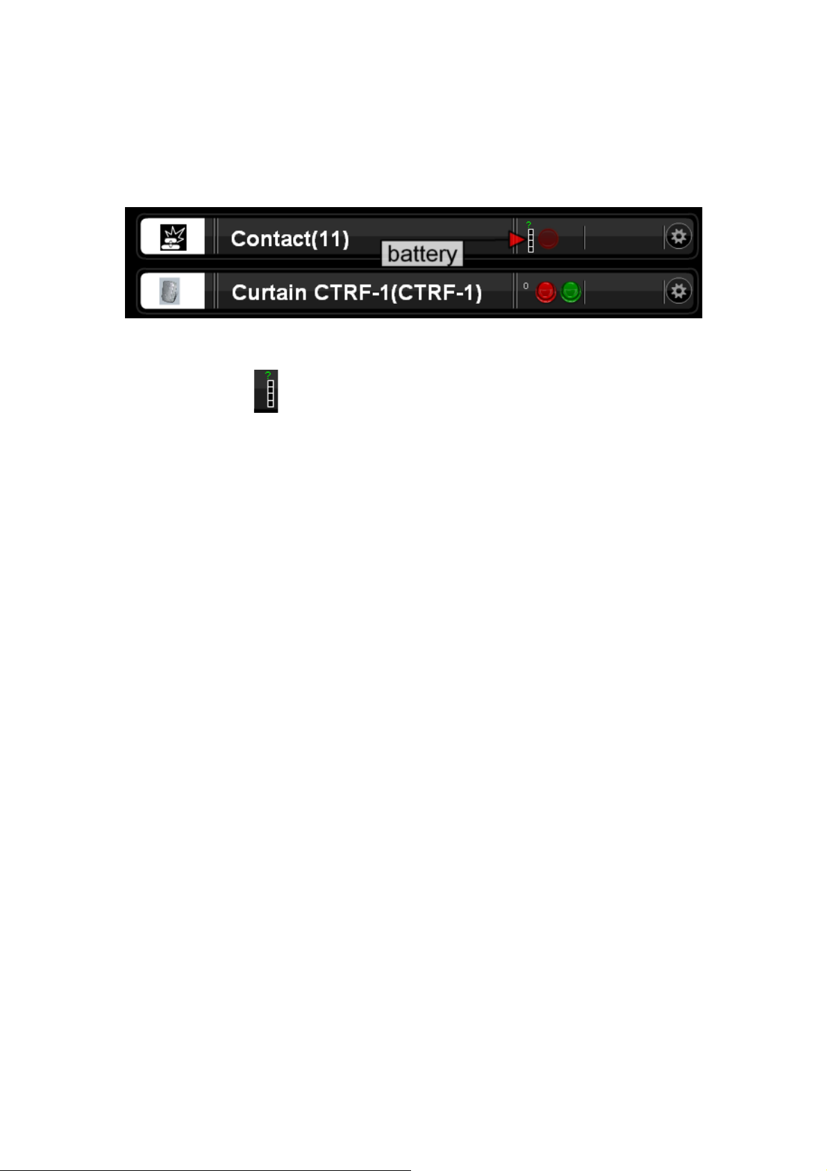
If the battery status of the battery-power device is too low, a log will be added with the
device name. In addition, we will show an icon in front of the device in the device
manager.
In the battery icon . The ‘?’ means that the device has not reported its battery
status yet. The device will report battery status every 30 minutes. When its battery
level is low, HSC-200 will generate a message which need to be confirmed by the
users.
Chapter 4 Scenario Editor
The scenario editor is the most powerful feature of the HSC-200. It provides a much
advanced replacement of the macro definition of other systems. Although HSC-200
provides python-based framework which allow users to download new plug-ins to
extend the functionalities, the scenario editor should be the preferable solution most
of the time. The system building by scenario editor is easier to maintain and extended.
The scenario editor is the most power home automation CAD so far and the function
is continuous to grow.
4.1 What is scenario?
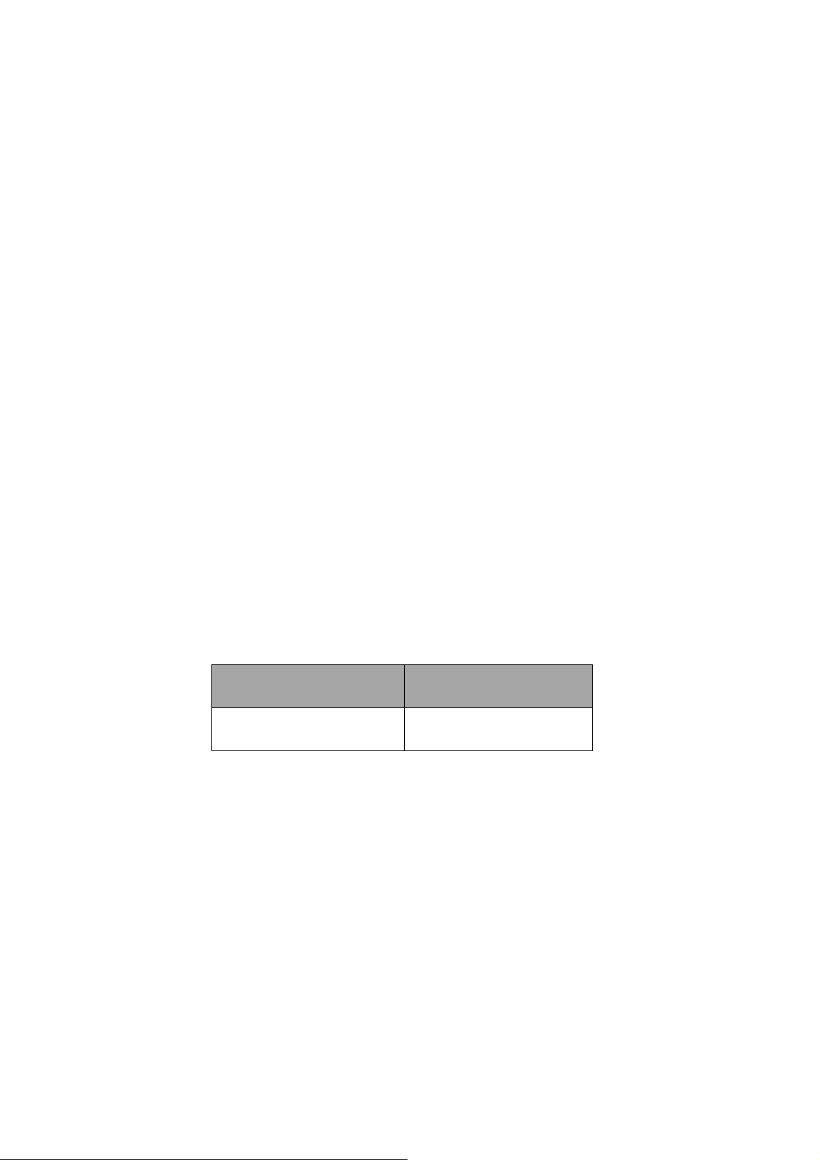
A scenario is a set of rules which defines how the system responses for input events.
For each input events, such as motion events or human input events, we can define it
to trigger one or more actions. For example, we can define a rule which call the action
on of the light switch when the motion sensor is triggered.
Signal Action
Motion is triggered Light switch turns on
In addition to simple connections between physical devices, we can insert logical
devices between them to perform more complex functions. In the scenario editor, we
provides the following logical devices
z Loop device
Sequencer
z Timer devices
24x7 timer

real-time timer
countdown timer
z Logic devices
XOR
AND
OR
z Value comparator
Max
Min
Range
The scenario editor is a complete visual programmer environment, which enable us to
compose program to control the equipments without a line of code. The scenario
editor will enable non-programmer to implement the function they want.
4.2 Visual programming
Traditionally, a sophisticated home automation system is composed by a
programming language. Typically, it is a scripting language. Therefore, a programmer
is required for the home automation project.
It might not be problem to hire a programmer to write the program. However, it’s hard
to hire a programmer which understands the home automation system. The HSC
provides the visual programming environment, called scenario editor, to allow
non-programmer to setup the system. Under this environment, HSC provides a CAD
to help installers to write the program. Like the traditional CAD, HSC represent all
devices as a block and then allow installers to build connections between pins of the

block. The function of a connection is actually decided by both ends of the connection
as well as the mapping of signals and actions.
Each connections contains the following parameters
z Origin signal or state
z target action
z Mapping from the signal or states to the actions.
The scenario editor provides visual representation of the all connections and editor to
change these parameters.
A programming language need to provide the following entitles
z Value calculation
z Condition
z Loop
z Variables
z Functions
4.2.1 Condition
The condition devices, such as MIN/MAX/RANGE/AND/OR/XOR provides the
condition statement of the usual programming language.
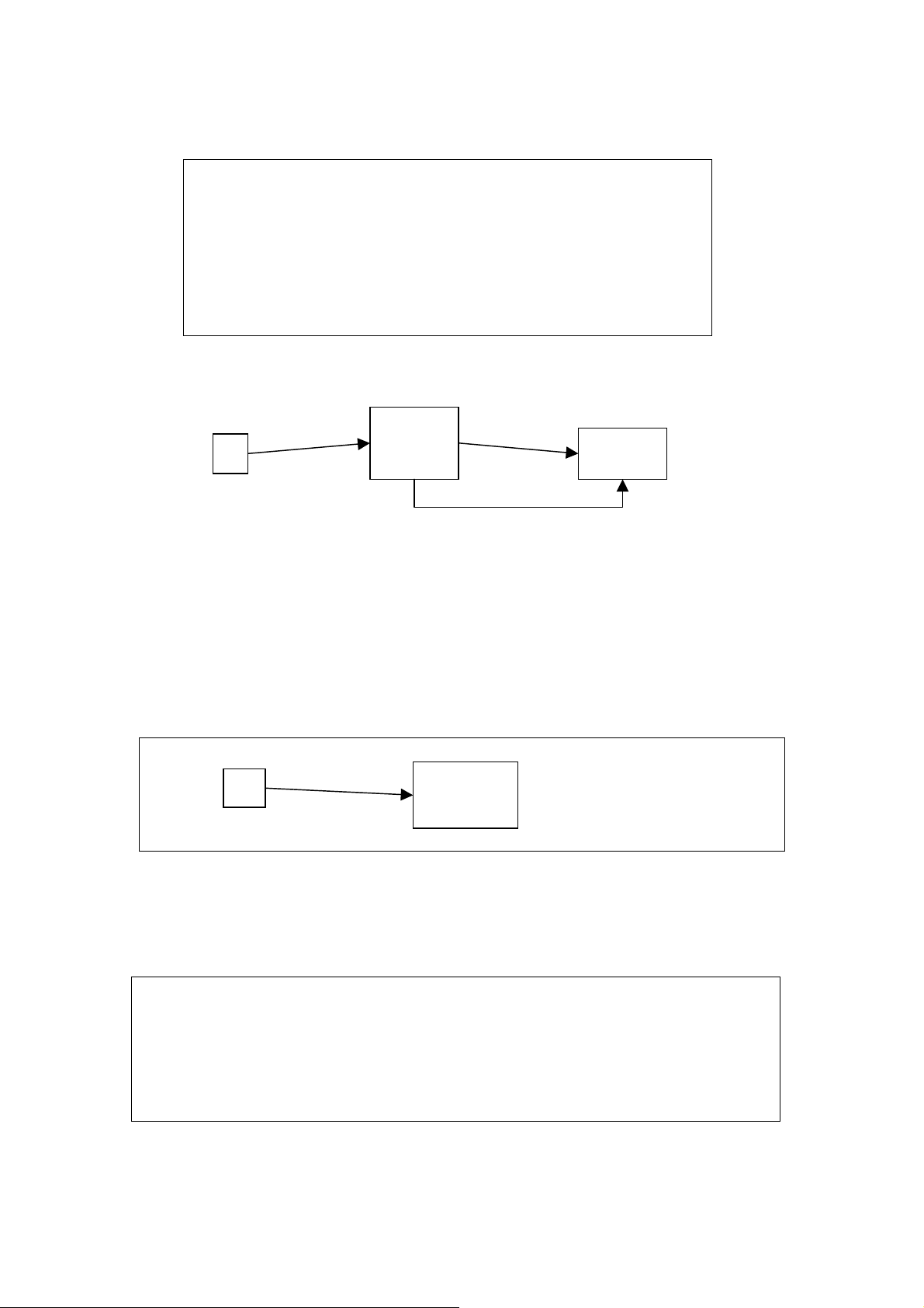
if (a>10)
light.position = ‘on’;
else
light.position = ‘off’;
RANGE
a
4.2.2 Variables
The state of a node provides the variable storage. The variable node can be used to
keep the state permanently. This node can be used to convert a signal to a state.
a
>10
variable
on
Light
off
4.2.3 loop
While(stop) {
Light.toogle();
}
 Loading...