

Homeright Power-Flo Pro 2800 Instruction Manual
mWARNING TO REDUCE THE RISK OF INJURY, USER
MUST READ AND UNDERSTAND INSTRUCTION MANUAL.
FOR HOUSEHOLD USE ONLY.
KEEP CHILDREN AWAY FROM WORKING AREA.
For Customer Service Call:
1-800-264-5442 or 763-780-5115
8 a.m. to 5 p.m. CST.
POWER-FLO
2800
PRO
Pistola rociadora sin
aire Power-Flo Pro
2800 1/2 HP
mADVERTENCIA PARA DISMINUIR LOS RIESGOS DE
LESIONES, EL USUARIO DEBE LEER Y ENTENDER EL MANUAL
DE INSTRUCCIONES.
SÓLO PARA USO DOMÉSTICO.
MANTENGA A LOS NIÑOS LEJOS DEL ÁREA DE TRABAJO.
Para comunicarse con el departamento de servicio al
cliente, llame al: 1-800-264-5442 o 763-780-5115
de 8 a.m. a 5 p.m. hora del Centro de los Estados Unidos.
Pistolet Pulvérisateur
sans air comPrimé
Power-Flo Pro 2800
1/2
HP
mAVERTISSEMENT POUR RÉDUIRE LES RISQUES DE
BLESSURE, L’UTILISATEUR DOIT LIRE ET COMPRENDRE LE
MANUEL D’INSTRUCTION.
DESTINÉ À UN USAGE DOMESTIQUE SEULEMENT.
TENEZ LES ENFANTS ÉLOIGNÉS DE L’AIRE DE TRAVAIL.
Pour le service à la clientèle, appelez au :
1-800-264-5442 ou 763-780-5115
8 h à 17 h, heure normale du Centre.
ENGLISH • FRANÇAIS • ESPAÑOL
1
800879 POWER-FLO
®
PRO 2800
PLEASE READ AND SAVE THIS INSTRUCTION MANUAL
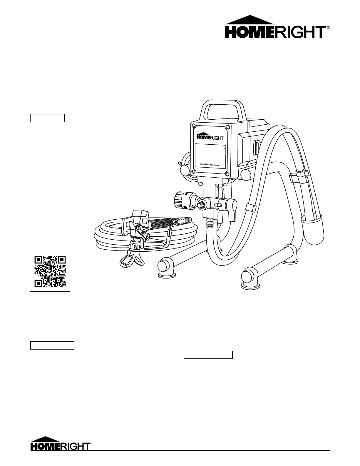
Power-Flo® Pro 2800
1/2 HP airless sPray Gun

2
800879 POWER-FLO® PRO 2800 ENGLISH
IMPORTANT SAFEGUARDS ...................................................................................................................................................................................3
m Warnings .....................................................................................................................................................................................................3
Grounding Instructions .....................................................................................................................................................................................5
Extension Cords ...............................................................................................................................................................................................5
PARTS LIST ...........................................................................................................................................................................................................6
FAST START QUICK REFERENCE GUIDE ...............................................................................................................................................................7
HOW TO USE ..........................................................................................................................................................................................................8
Unpacking.........................................................................................................................................................................................................8
Operating ..........................................................................................................................................................................................................9
Start Up ..........................................................................................................................................................................................................11
Tips ................................................................................................................................................................................................................. 11
MAINTENANCE & SERVICING .............................................................................................................................................................................12
Clean Up Instructions .....................................................................................................................................................................................13
Storing ............................................................................................................................................................................................................ 13
Winterize and Long Term Storage .................................................................................................................................................................14
TROUBLESHOOTING ............................................................................................................................................................................................15
TWO-YEAR LIMITED WARRANTY ...................................................................................................................................................................... 44
Table of Contents

3
800879 POWER-FLO® PRO 2800 ENGLISH
IMPORTANT SAFEGUARDS
SAVE THIS MANUAL
Keep this manual for the safety warnings and precautions, assembly,
operating, inspection, maintenance and cleaning procedures. Write
the product’s serial number in the back of the, manual (or month and
year of purchase if product has no number), Keep this manual and
the receipt in a safe and dry place for futurereference.
IMPORTANT SAFETY INFORMATION
In this manual, on the labeling, and all other information provided
with this product:
The safety alert symbol is used to alert you to potential personal
injury hazards. Obey all safety messages that follow this symbol to
avoid possible injury or death.
m DANGER indicates a hazardous situation which, if not avoided, will
result in death or serious injury.
m WARNING indicates a hazardous situation which, if not avoided,
could result in death or serious injury.
m CAUTION, used with the safety alert symbol, indicates a hazardous
situation which, if not avoided, could result in minor or moderate
injury.
NOTICE is used to address practices not related to personal injury.
CAUTION without the safety alert symbol, is used to address
practices not related to personal injury.
Read all safety warnings and instructions. Failure to follow the
warnings and instructions may result in electric shock, fire and/
or serious injury. Save all warnings and instructions for future
reference. The term “power tool” in the warnings refers to your lineoperated (corded) 1/2 HP Airless Spray Gun.
Work Area Safety
• Keep work area clean and well lit. Cluttered or dark areas invite
accidents.
• Do not operate power tools in explosive atmospheres, such as
in the presence of flammable liquids, gases or dust. Power tools
create sparks which may ignite the dust or fumes.
• Keep children and bystanders away while operating a power tool.
Distractions can cause you to lose control.
Electrical Safety
• Power tool plugs must match the outlet. Never modify the plug in
any way. Do not use any adapter plugs with grounded power tools.
Unmodified plugs and matching outlets will reduce risk of electric
shock.
• Avoid body contact with grounded surfaces such as pipes,
radiators, ranges and refrigerators. there is an increased risk of
electrical shock if your body is grounded.
• Do not expose power tools to rain or wet conditions. Water entering
a power tool will increase the risk of electrical shock.
• Do not abuse the power cord. Never use the cord for carying,
pulling or unplugging the power tool. Keep cord away from heat,
oil, sharp edges or moving parts. Damaged or entangled cords
increase the risk of electric shock.
• When operating a power tool outdoors, use an extension cord
(not included) suitable for outdoor use. Use of a cord suitable for
outdoor use reduces the risk of electric shock.
Personal Safety
• Stay alert, watch what you are doing and use common sense when
operating a power tool. Do not use a power tool while you are tired
or under the influence of drugs, alcohol or medication. Amoment
of inattention while operating power tools may result in serious
personal injury.
• Use personal protective equipment. Always wear eye protection.
Safety equipment such as dust mask, and non-skid shoes will
reduce the risk of personal injuries.
• Prevent unintentinal starting. Ensure the switch is in the off
position before connecting to power source.
• Do not overreach. Keep proper footing and balance at all times. this
enables better control of the power tool in unexpected situations.
• Dress properly. Wear protective clothing as required by coating
manufacturer.
• Only use safety equipment that has been approved by an
appropriate standards agency. Unapproved safety equipment may
not provide adequate protection. Eye protection must be ANSIapproved and breathing protection must be NIOSH-approved for
the specific hazards in the work area.
Specific Safety Warnings
• Maintain labels and nameplates. these carry important safety
information.
• Always wear ANSI-approved safety goggles and NIOSH-approved
ventilator or face mask. Some face masks, such as paper filters,
provide only limited protection against harmful sprays and fumes.
refer to the safety documents provided with the materials you
are spraying or an industrial safety expert when determining the
appropriate respritory protection.
• Wear heavy duty workgloves, NIOSH-approved hearing protection,
long-sleeved shirts, full length jeans and non-skid safety shoes.
• This high-pressure airless sprayer is capable of producing 3,000
PSI and is capable of injecting toxins into the body and cause
serious injury. In the event accidental injection occurs, seek
medical attention immediately.
• Never point or spray toward any person or animal.
• Never place your hands, fingers or any part of your body in front
of the spray nozzle if the spray gun is not disconnected and
depressurized.
• Test spray on scrap material before spraying work material. High
pressure spray may damage persons or property.
• Always use the Nozzle Tip Guard. Never spray without the Guard in
place. Only use a Nozzle Tip specified by the manufacturer. Always
relieve pressure before removing the Nozzle Tip to clean.
• Do not leave the unit energized or under pressure while
unattended. When the unit is not in use, turn off the unit and
relieve the pressure.
• Always engage the Trigger Lock when not spraying. Make sure the
Trigger Lock is functioning properly.
• Make sure all connections are secure before operating the unit.
m WARNINGS

4
800879 POWER-FLO® PRO 2800 ENGLISH
• Always check the Hose for damage. Replace the Hose if damaged.
Do not kink or excessively bend the Hose.
• Route hoses and cables away from traffic areas, sharp edges,
moving, parts, and hot surfaces.
• Never spray materials near fire, flames, electrical sparks, or any
other ignition source. Never smoke when spraying or in the vicinity
of spraying. Never smoke unless the area has been thoroughly
aired out. Always provide good ventilation. Vent during and after
spraying to eliminate any enclosed explosive atmosphere
• Read and understand the instructions and precautions provided by
the manufacturer of each paint/solvent before using the sprayer.
Never spray the solvents listed below in any Sprayer containing
aluminum:
• 1, 1, 1-Trichloroethane
• Methylene Chloride
• Halogenated hydrocarbons
• Never spray the solvents mentioned above in any Sprayer
containing aluminum. Never use these solvents for cleaning
equipment. Never use any solvent if in doubt if its composition
or compatibility with aluminum, other materials or this Airless
Sprayer. Such use can cause serious chemical reaction and
equipment rupture, resulting in property damage and/or
personal injury.
• If used with only water-based materials, do not spray or clean with
flammable liquids.
• If used with only water-based or mineral spirit-type materials with
a minimum flash point of 69.8° Fahrenheit, do not spray or clean
with liquids having a flash point less than 69.8° Fahrenheit.
• Paint or solvent flowing through the equipment is capable of
producing static electricity. Static electricity creates a risk of fire
or explosion in the presence of paint or solvent fumes.
• All parts of the Airless Sprayer and objects in and around the spray
area must be properly grounded to protect against static discharge
and sparks.
• Use only conductive metal containers placed on a grounded
surface such as concrete. Do not place the container on a nonconductive surface such as paper or cardboard, which interrupts
grounding continuity. Always connect a ground wire to the
container by clamping one end to the container and the other end
to a ground such as a water pipe.
• To maintain grounding continuity when flushing or relieving
pressure, hold the metal part of the Spray Gun firmly to the side of
a grounded metal container. Then trigger the Spray Gun.
• Use only conductive or grounded high pressure airless paint
sprayer hoses specified by the manufacturer.
• Make sure all containers and collection systems are grounded to
prevent static discharge.
• Do not operate light switches, engines, or similar spark producing
products in the spray area.
• Keep the area free of paint and solvent containers, rags, and other
flammable materials.
• Always have multiple ABC class fire extinguishers nearby.
• Avoid unintentional starting. Prepare to begin work before turning
on the tool.
• This unit is provided with a thermally protected reset. If an
overload occurs, the reset disconnects the Motor from the
powersupply.
• When the thermally protected reset disconnects the Motor from
the power supply, relieve pressure by turning the Pressure Adjust
Knob (69A) to “OFF”.
• Turn the Power Switch (33A) to its “OFF” position.
• The cause of the overload should be corrected before restarting.
(See “Troubleshooting” section.)
• Press the Reset Button at the bottom of the unit.
• Turn the Power Switch (33A) to its “ON” position to restart.
• This product is not a toy. Keep it out of reach of children.
• People with pacemakers should consult their physician(s) before
use. Electromagnetic fields in close proximity to heart pacemaker
could cause pacemaker interference or pacemaker failure. In
addition, people with pacemakers should:
• Avoid operating alone.
• Do not use with powerswitch locked on.
• Properly maintain and inspect to avoid electrical shock.
• Any power cord must be properly grounded. Ground Fault Circuit
Interrupter (GFCI) should also be implemented - it prevents
sustained electrical shock.
• Some dust and fumes created by painting, power sanding, sawing,
grinding, drilling, and other construction activities, contains
chemicals known [to the State of California] to cause cancer, birth
defects, or other reproductive harm. Some examples of these
chemicals are:
• Lead from lead-based paints.
•
Crystalline silica from bricks and cement or other masonry products.
• Arsenic and chromium from chemically treated lumber.
• Your risk from these exposures varies, depending on how often you
do this type of work. To reduce your exposure, to these chemicals:
work in a well ventilated area, and work with approved safety
equipment, such as those dust masks that are especially designed
to filter out microscopic particles, (California Health & Safety Code
§ 25249.5, et seq.).
• WARNING: The brass components of this product contain lead, a
chemical known to the State Of California to cause birth defects
(or other reproductive harm). (California Health & Safety Code §
25249.5, et seq.).
• WARNING: Handling the Power Cord (37A) on this product will
expose you to lead, a chemical known to the State of California
tocause cancer, and birth defects or other reproductive harm.
Wash hands after handling. (California Health & Safety Code §
25249.5, et seq.).
• The warnings, precautions, and instructions discussed in this
instruction manual cannot cover all that may occur. It must be
understood by the operator that common sense and caution
are factors which cannot be built into this product/but must be
supplied by the operator.
IMPORTANT SAFEGUARDS
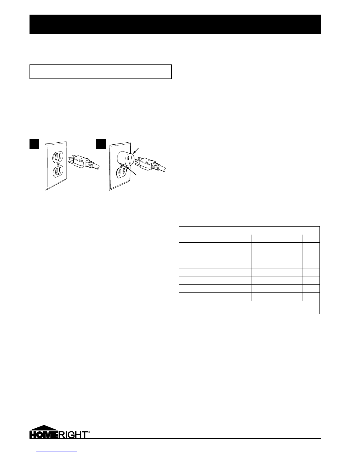
GROUNDING
TO PREVENT ELECTRIC SHOCK AND DEATH FROM INCORRECT
GROUNDING WIRE CONNECTION:
Check with a qualified electrician if you are in doubt as to whether
the Outlet is properly grounded. Do not modify the Power Cord Plug
provided with the tool. Never remove the grounding prong from the
Plug. Do not use the tool if the Power Cord or Plug is damaged. If
damaged, have it repaired by a service facility before use. Ifthe Plug
will not fit the Outlet, have a proper Outlet installed by a qualified
electrician.
Grounded Tools with 3-Prong Plug
• Tools marked with “Grounding Required” have a three wire cord
and three prong grounding plug. The plug must be connected to a
properly grounded, outlet. If the tool should electrically malfunction
or break down, grounding provides a low resistance path to carry
electricity away from the user, reducing the risk of electric shock.
(Figure 1)
• The grounding prong in the plug is connected through the green
wire inside the cord to the grounding system in the tool. The green
wire in the cord must be the only wire connected to the tool’s
grounding system and must never be attached to an electrically
“live” terminal. (Figure 1)
• The tool must be plugged into an appropriate outlet, properly
installed and grounded in accordance with all codes and
ordinances. The plug and outlet should look like those in Figure 1.
EXTENSION CORDS
• Grounded tools require a three wire extension cord. Double
Insulated tools can use either a two or three wire extension cord.
• As the distance from the supply outlet increases, you must use
a heavier gauge extension cord. Using extension cords with
inadequately sized wire causes a serious drop in voltage resulting
in loss of power and possible tool damage. (See Table A.)
• The smaller the gauge number of the wire, the greater the capacity
of the cord. For example, a 14 gauge cord can carry a higher
current than a 16 gauge cord. (See Table A.)
• When using more than one extension cord to make up the total
length, make sure each cord contains at least the minimum wire
size required. (See Table A.)
• If you are using one extension cord for more than one tool, add the
nameplate amperes and use the sum to determine the required
minimum cord size. (See Table A.)
• If you are using an extension cord outdoors, make sure it is
marked with the suffix “W-A” (“W’ in Canada) to indicate it is
acceptable for outdoor use.
• Make sure the extension cord is properly wired and in good
electrical condition. Always replace a damaged extension cord or
have it repaired by a qualified electrician before using it.
• Protect the extension cords from sharp objects, excessive heat,
and damp or wet areas.
Recommended Minimum Wire Gauge
for Extension Cords* (120/140 Volt)
Nameplate Amps
(at full load)
Extension Cord Length
25' 50' 75' 100' 150'
0 – 2.0 18 18 18 18 16
2.1 – 3.4 18 18 18 16 14
3.5 – 5.0 18 18 16 14 12
5.1 – 7.0 18 16 14 12 12
7.1 – 12.0 18 14 12 10 —
12.1 – 16.0 14 12 10 — —
16.1 – 20.0 12 10 — — —
* Based on limiting the line voltage drop to 5 Volts at 150%
of the rated amperes.
Grounded
Outlet
Grounded
Outlet Box
Adapter
Tab and
Grounding
Screw
A B
5
800879 POWER-FLO® PRO 2800 ENGLISH
IMPORTANT SAFEGUARDS
m WARNING
Figure 1
6
800879 POWER-FLO® PRO 2800 ENGLISH
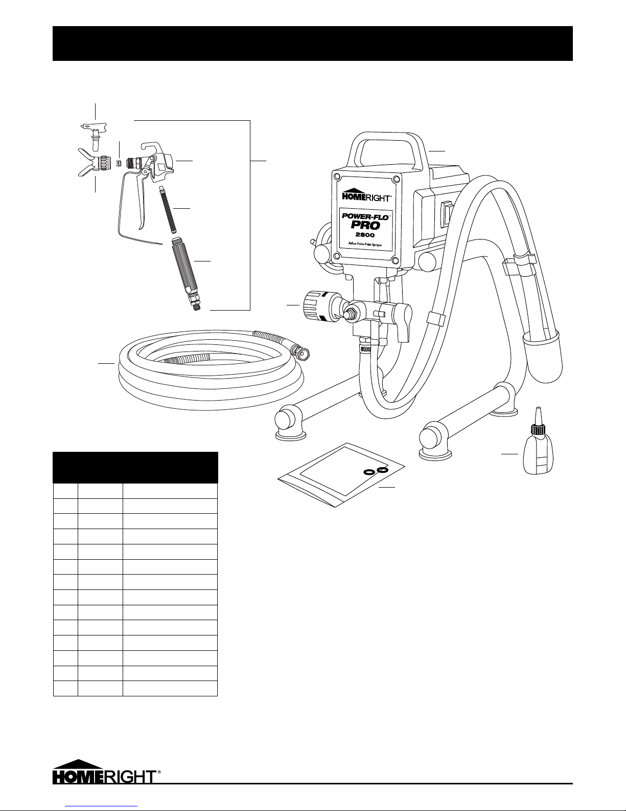
PARTS LIST
If you cannot obtain parts and
accessories at your local retail dealer,
call or visit www.homeright.com
Phone: 763-780-5115
1-800-264-5442
8:00 a.m. to 5:00 p.m. CST.
Item
Customer
Service
Part No. Description
1a C800836 Replacement Latex Tip, 515
1b C800837 Replacement Stain Tip, 413
2 C800862 Saddle and Seal
3 Not Available Spray Gun Housing
4 C806060 Spray Tip Guard
5a C800835 Replacement Filter, 100
5b C800844 Replacement Filter, 50
6 Not Available Gun Handle
7 C800863 Spray Gun with Swivel
8 C800861 Hose
9 C800879 Power-Flo Pro 2800
10 C817348 Oil
11 C800875 Pump Repair Kit
12 C817939 Regulator Assy Pressure Control
1
2
3
7
5
4
6
8
12
9
10
11
7
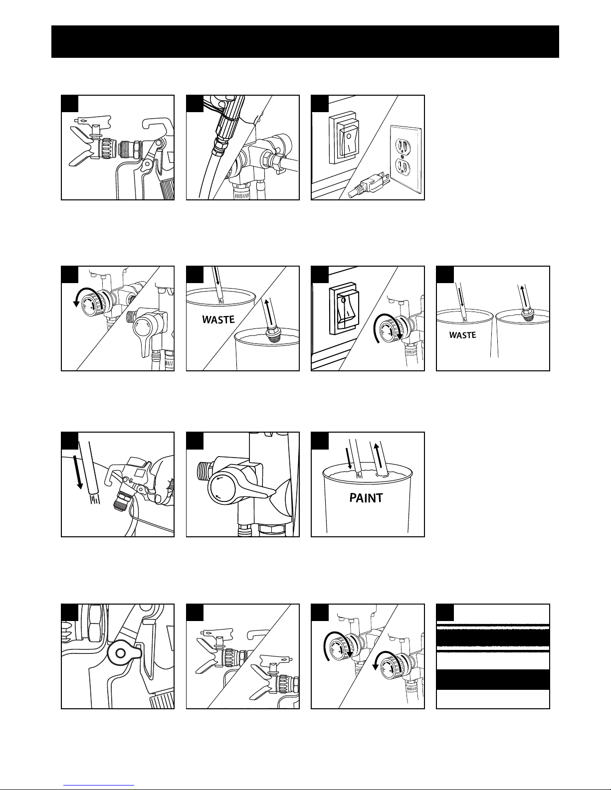
Priming
Spraying
This is only a quick reference. Read the entire instruction manual prior to using the product.
Submerge suction tube in paint. Turn Power Switch ON, and trigger gun into
waste pail. When paint comes out of return tube, turn Prime/Spray valve to
SPRAY. When paint comes out of gun, release trigger. Pump will build up
pressure and motor will stop.
Put trigger safety lever in locked
position.
NOTE: Always lock the trigger
when not in use, while performing
maintenance or during set-up and
cleaning.
1
P
R
I
M
E
S
P
R
A
Y
2
Install tip and guard on gun and hand
tighten. If tip clogs, reverse spray tip
to quickly clear obstructions without
dissasembly. (Refer to Page 8 for
assembly instructions)
Correct solid spray pattern
Incorrect spray pattern with “tails”
4
FAST START QUICK REFERENCE GUIDE
Transfer
Return Tube
to paint pail.
3
Setup
Remove spray tip and guard from gun.
During first use of Spray Gun, Spray Tip
and Guard will be off of the Spray Gun.
1
Connect hose to gun and sprayer.
2
Turn Power Switch OFF. Plug sprayer
into grounded outlet.
3
Turn pressure control knob
clockwise to increase pressure
and counter-clockwise to decrease
pressure at the gun.
bar/MPa/psi
3
bar/MPa/psi
Unlock trigger safety lever. Point gun
12" from surface and begin moving
gun before triggering. If tails persist at
highest pressure, switch to smaller tip
or thin material.
Flushing
Turn pressure control knob counterclockwise to minimum pressure.
Turn Spray/Prime valve to PRIME.
bar/MPa/psi
1
Place Return Tube into waste pail.
Submerge suction tube in water
(water-based materials) or thinner/
cleaner solution (oil-based materials.)
2 4
Turn Power Switch ON. Turn Pressure
Control Knob clockwise until pump
starts.
3
bar/MPa/psi
Allow fluid to flow out of prime tube
into waste pail for 30-60 seconds.
Turn power switch OFF.
P
R
I
M
E
S
P
R
A
Y
1 2
Spray
Clean
BULLETIN
If sprayer will not prime, remove
suction tube from unit and insert
a screwdriver to release the inlet
valve. Refer to D in the “Sprayer
starts, but does not draw in paint ...”
section in Troubleshooting.
800879 POWER-FLO® PRO 2800 ENGLISH
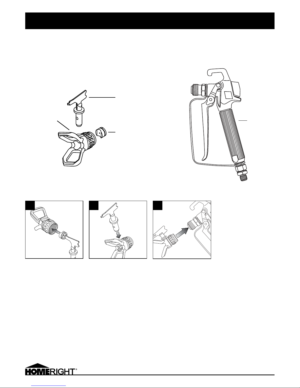
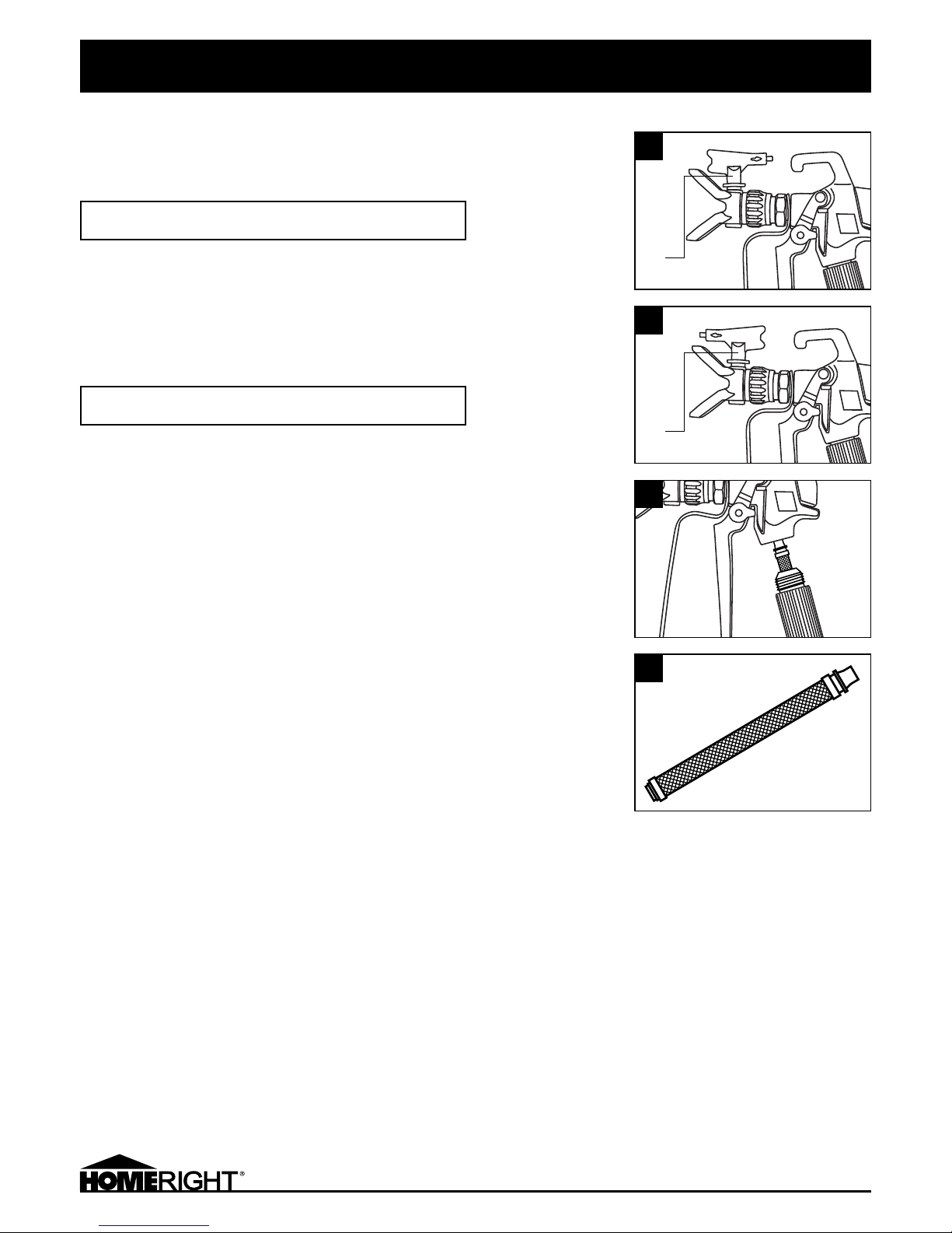
SPRAY GUN ASSEMBLY
When assembling the spray gun, it is important to correctly insert the Saddle Seat-Washer assembly.
The Saddle Seat has a curved section designed to align with the Spray Tip when assembled.
The Saddle Seat and the plastic washer come pre-assembled.
POWER-FLO® PRO 2800 SPRAY GUN ASSEMBLY
Spray
Gun
Spray Tip
Saddle Seat-Plastic
Washer Assembly
Spray
Guard
Insert Saddle Seat first into
Spray Guard, as shown, with
the curved part of the Saddle
aligned with the Spray Tip hole.
Use the plastic pointer on the
Spray tip to fully seat, if needed.
Actual product may differ from image shown.
1
Insert Spray Tip into Spray
Guard. The curved part of the
Saddle Seat should fit with the
Spray Tip.
Keep the Spray Guard pointing
down to prevent the Saddle
Seat-Washer assembly from
falling out.
2
3
Keeping the Spray Guard and
Gun pointing down to prevent
the Saddle Seat-Washer
assembly from falling out,
screw the Guard to the Gun
and hand tighten.
9
800879 POWER-FLO® PRO 2800 ENGLISH
UNPACKING
When unpacking check to make sure that the item is intact and undamaged. If any parts are
missing or broken, please call the number on the front of this manual as soon as possible.
ASSEMBLY INSTRUCTIONS
Read the ENTIRE IMPORTANT SAFETY INFORMATION section at the beginning of this manual
including all text under subheadings therein before set up or use of this product.
WARNING: To prevent serious injury from accidental operation, turn the Power Switch
(Figure C ) of the High Pressure Airless Sprayer to its “OFF” position and unplug the Sprayer
from its electrical outlet before assembly procedures.
NOTE: For additional information regarding the parts listed in the following pages, refer to
the Assembly Diagram near the end of this manual.
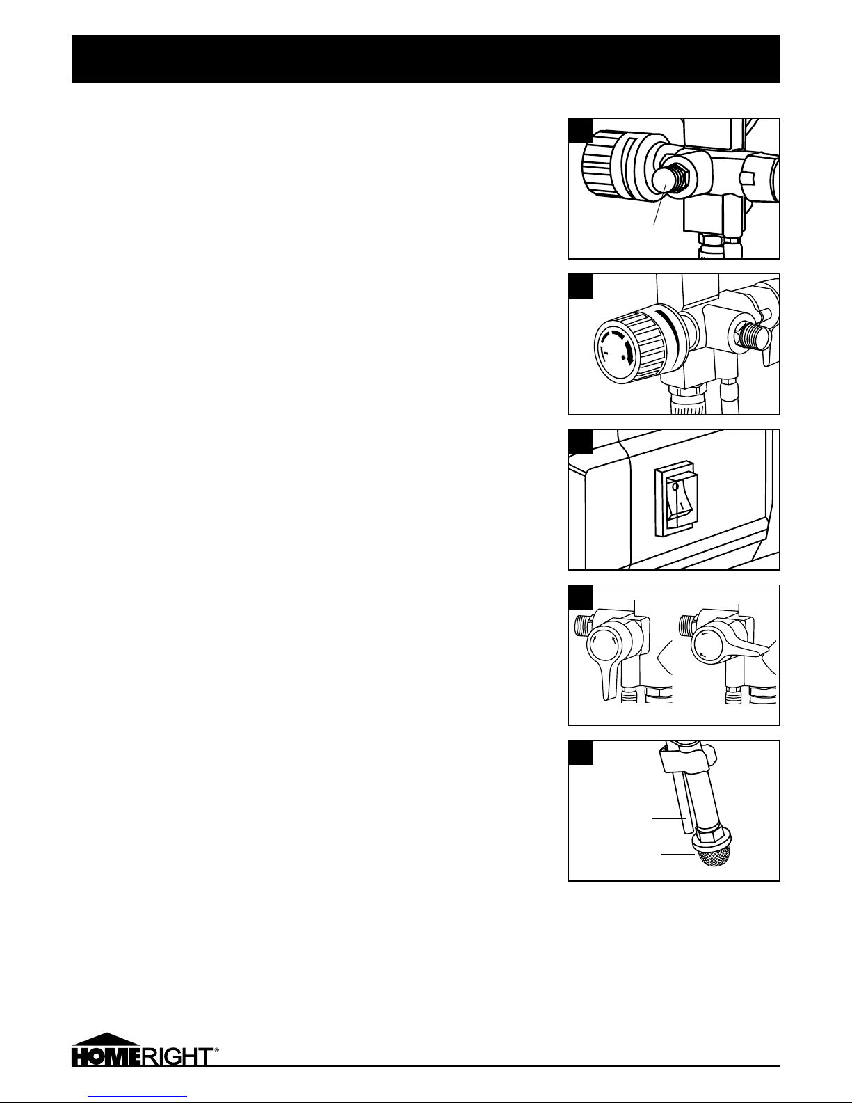
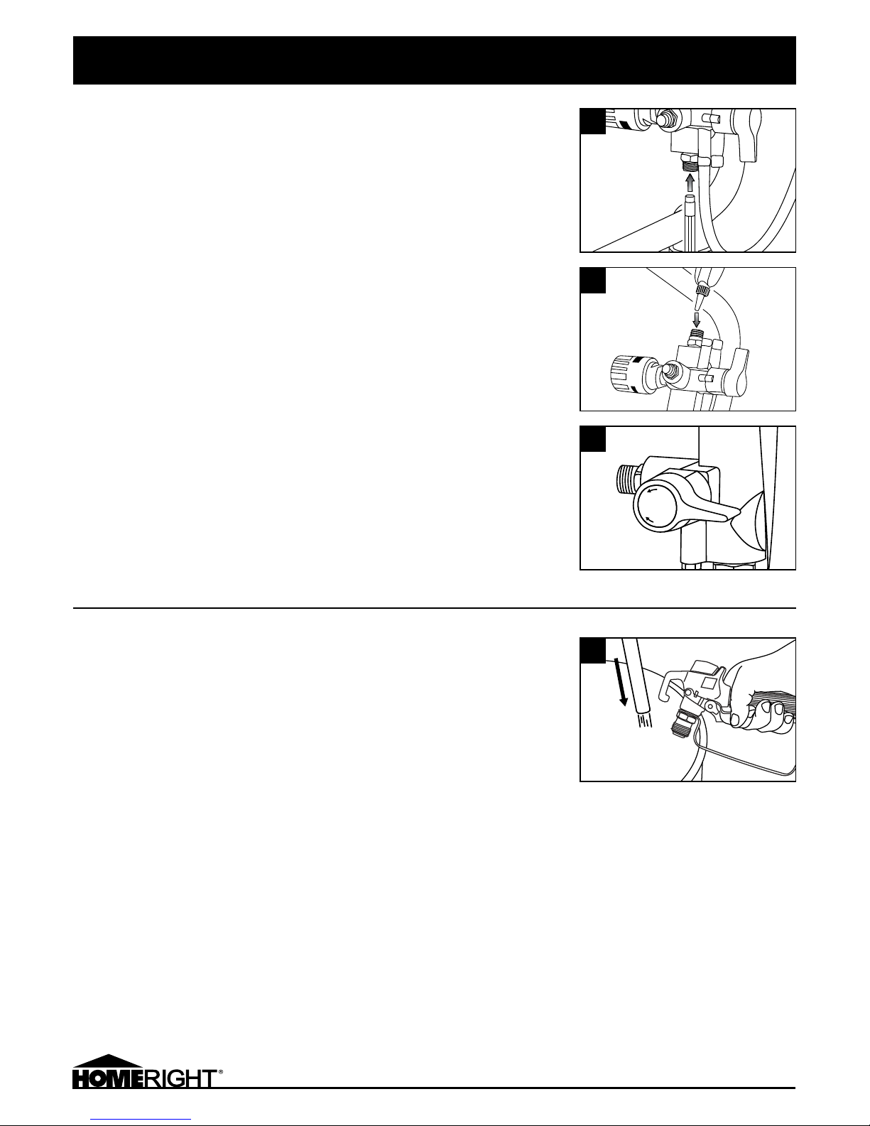
Remove the protective Plastic Cap from the Paint Output Coupler. Then attach the High
Pressure Paint Hose. (Figure A ) Attach spray gun to other end of hose. Tighten with wrench.
Do not attach spray tip and guard.
PRODUCT FEATURES
• Pressure Control Knob: The Pressure Control Knob controls the output pressure of paint.
Turn the Knob clockwise to increase pressure and counterclockwise to decrease pressure.
(Figure B)
• Power Switch: Press to turn the Sprayer on or off. (Figure C )
• Prime/Spray Knob: Turn the Prime/Spray Knob horizontally to run the Sprayer.
Turn the knob vertically to run the Sprayer in its prime/clean” mode. (Figure D )
• Output Coupler: The Spray Gun Hose connects to the paint Output Coupler. (Figure A )
• Suction Tube: The Suction Tube sucks paint from the container into the Spray Gun.
(Figure E )
• Return Tube: When system pressure is released or when priming pump, the paint flows
from the Return Tube. (Figure E )
HOW TO USE
bar/MPa/psi
A
B
C
E
Output coupler
P
R
I
M
E
S
P
R
A
Y
P
R
I
M
E
S
P
R
A
Y
Prime Spray
Suction Tube
Return Tube
D
10
800879 POWER-FLO® PRO 2800 ENGLISH
IMPORTANT SAFETY INFORMATION section at the beginning of this manual including all text
under subheadings therein before set up or use of this product.
Preparing a New Sprayer
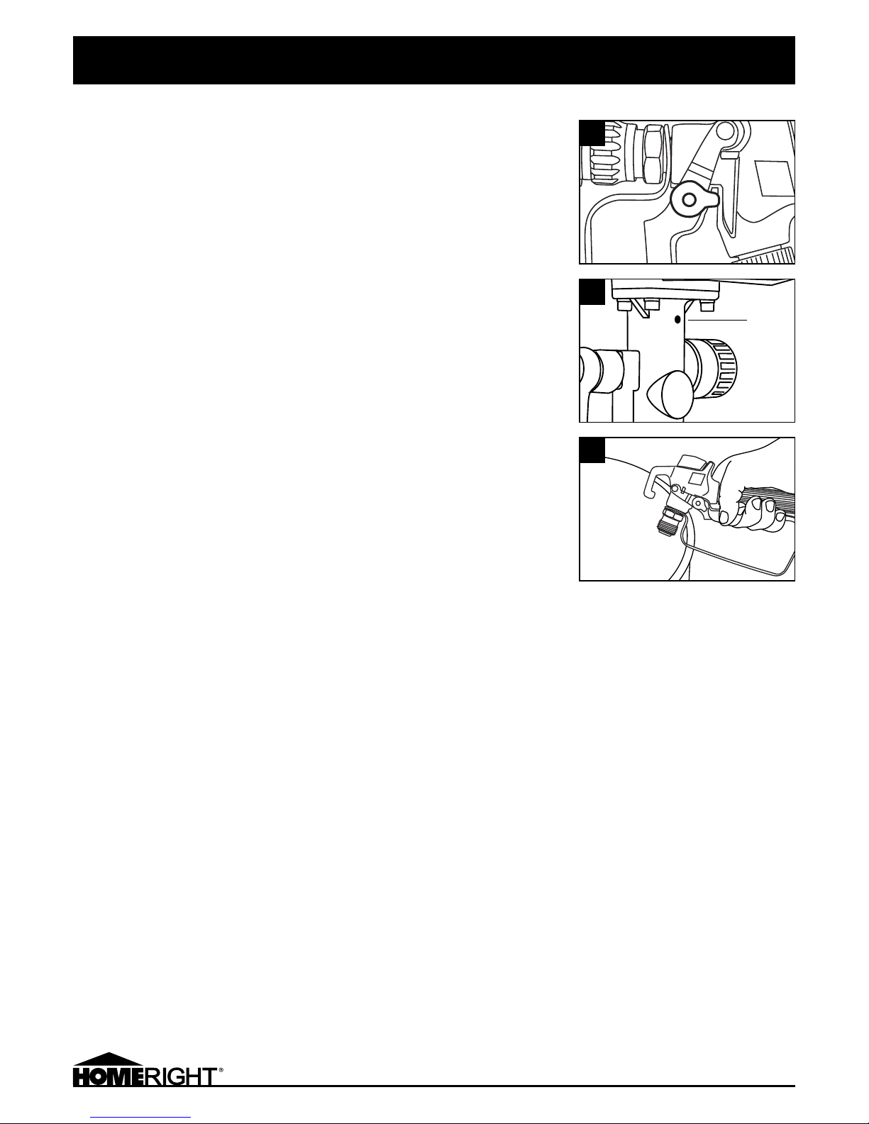
Always keep the trigger lock on the spray gun in the locked position while preparing the
system. (Figure F )
• Place the suction tube into a container of soapy water.
• Place the return tube into a metal waste container.
• Turn Pressure Control Knob all the way left (counter-clockwise) to minimize pressure.
(Figure B , page 9)
• Move the Prime/Spray valve down to the Prime position.
• Turn the unit on by moving the On/Off switch to On. (Figure C , page 9)
• Turn Pressure Control Knob to right to start pump.
• Allow the sprayer to run for 15-30 seconds to flush the test fluid out through the return
hose and into the waste container.
• Turn the unit off by moving the On/Off switch to Off. (Figure C , page 9)
• Submerge suction tube in paint. Turn Power Switch ON, and trigger gun into waste pail.
When paint comes out of return tube, turn Prime/Spray valve to SPRAY. When paint comes
out of gun, release trigger. Pump will build up pressure and motor will stop.
• Transfer return tube to paint pail.
• Attach spray tip and guard. Do not over tighten.
• Sprayer is now ready for start up.
Workpiece and Work Area Set Up
• Designate a work area that is clean and well-lit. The work area must not allow access by
children or pets to prevent injury and distraction.
• Route the Power Cord along a safe route to reach the work area without creating a tripping
hazard or exposing the Power Cord to possible damage. The Power Cord must reach the
work area with enough extra length to allow free movement while working.
• There must not be hazardous objects such as utility lines or foreign objects nearby that
will present a hazard while working.
GENERAL OPERATING INSTRUCTIONS
NOTE: Prior to use, add approximately 5 drops of machine oil (Figure G ). Adding this oil is a
daily requirement each time the Spray Gun is used.
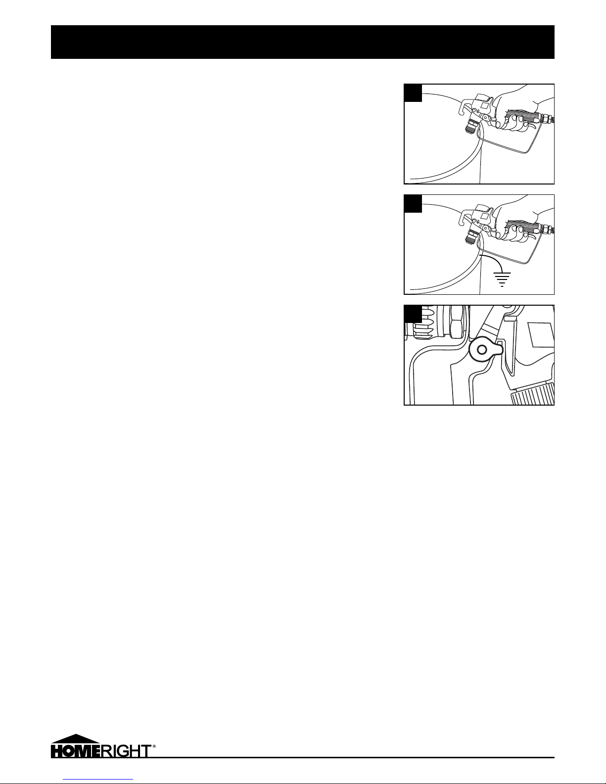
Prior to operating the Sprayer, know in advance how to release pressure in the unit’s system:
• Engage the Safety Lock on the Spray Gun. (Figure F )
• Turn the Power Switch to its “OFF” position. (Figure C , page 9)
• Turn the Pressure Adjust Knob to it’s lowest setting. (Figure B, page 9)
• Unlock the Spray Gun by turning the Safety Lock to the unlocked position. (Figure F )
• Hold the Spray Gun firmly against the side of a grounded container. (Figure H )
• Spray the paint into the container to relieve the system pressure.
• Lock the Spray Gun by turning the Safety Lock to the locked position. (Figure F )
• Turn the Prime/Spray Knob to its “PRIME” position. (Figure D , page 9)
HOW TO USE
F
G
H
Add Oil
11
800879 POWER-FLO® PRO 2800 ENGLISH
START UP
IMPORTANT: Do not run the Sprayer dry for more than 30 seconds. Doing so can damage the
Pump Packing.
NOTE: Before spraying the actual workpiece, it is recommended to test spray on a scrap board.
• Unlock the Trigger Safety Lock. (Figure F , page 10)
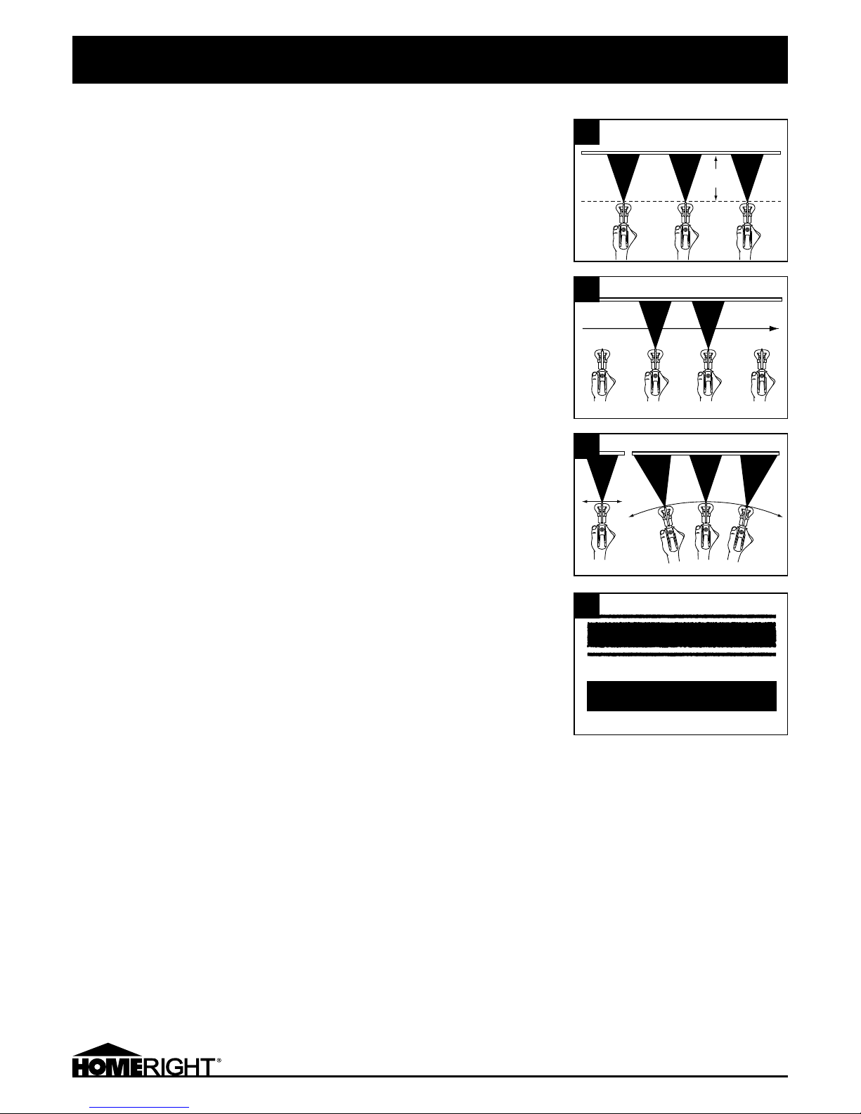
• Make sure the Spray Tip faces toward the workpiece to be painted.
• Hold the Spray Gun perpendicular and about 12-14 inches from the workpiece. (Figure I )
• Move the Spray Gun first, then pull the Trigger to spray a test pattern. (Figure J )
• Slowly increase Pump pressure until coverage is uniform (no tails or gaps on edges).
(Figure L )
• To align the spray pattern, relieve pressure on the system. Align the Guard horizontally
to obtain a horizontal spray pattern. Align the Guard vertically to obtain a vertical spray
pattern.
PAINTING TIPS
Successful spray painting is a skill which requires knowledge of your equipment, familiarity
with your paint materials and experience.
Differences in paints, work materials and environmental conditions make every painting
task unique. For best results, practice with your painting mixture on scrap material before
beginning to paint your workpiece.
It is critical that the surface be properly prepared before painting. It will be difficult to
achieve a satisfactory painted surface if the original surface is dirty, rough, or wet.
Properly mask your paint surface from any adjacent areas you do not want to paint.
Usedrop cloths or other covers to protect adjacent objects from paint dust or overspray.
In most cases, it is best to move the paint spray from side to side, overlapping the previous
paint. To paint in this way, the spray pattern should be set to vertical.
It is important to prevent excess paint at the beginning and end of each stroke. Holding the
Spray Gun away from the workpiece, squeeze the Trigger to start the spray. Then move the
Spray Gun in to within 12-14 inches of the workpiece. Move the Spray Gun smoothly across
the workpiece, keeping a consistent distance. At the end of each stroke, pull the Spray Gun
away from the workpiece as you release the Trigger.
As you work, observe the way the paint accumulates on the work surface. It is more
important to maintain a good paint surface than to form an opaque (thick) paint coat.
Youcan always apply a second coat to get the coverage you want. If the surface is ruined,
however, you will have to start over with surface preparation.
If the surface does not smooth out in a few seconds after applying the paint, your paint
mixture is probably too thick. Thin your paint slightly and test on scrap material. If the paint
goes on very thin and threatens to run, stop spraying immediately. Add more paint to your
mixture to thicken the paint. Test on scrap material before resuming work.
HOW TO USE
12-14
inches
I
Start Trigger Release End
J
Correct Incorrect
Correct solid spray pattern
Incorrect spray pattern with “tails”
K
L
12
800879 POWER-FLO® PRO 2800 ENGLISH
MAINTENANCE AND SERVICING
IMPORTANT: Procedures not specifically explained in this manual must be performed only by
a qualified technician.
To Prevent Serious Injury From Accidental Operation
Prior to cleaning, lock the Gun Trigger, turn the Pressure Adjust Knob to “OFF”, then open the
Prime/Spray Knob to release all pressure.
Prior to storing or performing service and repairs, turn the Power Switch of the Sprayer to
its “OFF” position, unplug the Sprayer from its electrical outlet, and relieve all remaining
pressure from the system.
To Prevent Serious Injury From Tool Failure
Do not use damaged equipment. If abnormal noise or vibration occurs, have the problem
corrected before further use.
Before each use, inspect the general condition of the Airless Sprayer. Check for loose
screws, misalignment or binding parts, cracked or broken parts, damaged electrical wiring,
damaged hoses and any other condition that may affect its safe operation,
To Clear the Spray Tip
If Spray Tip clogs while spraying, rotate the Tip 180° to the “Clean position. (Figure M)
Pull the Trigger and spray to clear the Tip of any blockage. Take care to spray away from
workpiece in order to clear the clog. Rotate the Tip back to the “Spray” position and
continue spraying. (Figure N ) If the clogging continues, clean or replace the Spray Gun Filter.
(FigureP )
IMPORTANT: Do not use a needle or sharp object to clean the Tip, as damage to the Tip
mayresult.
To Change Spray Tips
Rotate the Spray Tip 90º. Remove the Spray Tip from the Nozzle Seat. Install a new Spray Tip
on the Nozzle Seat. Then rotate the Tip 90º to the “spray” position. (Figure N )
To Clean Spray Gun Filter
Unscrew the Spray Gun Handle (Figure O ) from the Gun Body to access the Filter. (Figure P )
Remove the Filter and use brush (not included) to clean with water (if used with water-based
paint) or solvent (if used with oil-based paint). Inspect Filter for pinholes, clogging, or other
damage. Replace if necessary. Reinstall the Filter. Then screw the Spray Gun Handle back
into the Gun Body. (Figure O )
MAINTENANCE AND SERVICING
M
P
O
m WARNING
m WARNING
Tip
Clean Position
N
Tip
Spray Position
13
800879 POWER-FLO® PRO 2800 ENGLISH
CLEAN UP
To Flush The System:
Clean with water if using a water-based paint. Clean with solvent if using an oil-based paint.
NOTE: Cleaning and flushing will also be required when changing color or type of paint i.e.,
water-based changing to oil-based.
• Lock the Gun Trigger. Turn the Pressure Control Knob to “OFF”. Then open the Prime/Spray
Knob to release all pressure.
• Remove spray tip and guard and place in cleaning fluid.
• Turn Pressure Control Knob to prime/clean mode.
• While the unit is running in prime/clean mode, lift the Return Tube, and Suction Tube out of
the container and allow 10-15 seconds to pump out the paint.
• Turn the Pressure Control Knob to “OFF”
• Place the Return Tube and Suction Tube in a container filled with clean water (if using
water-based paint) or clean solvent (if using an oil-based paint).
• Turn the Prime/Spray Knob to Prime mode. (Vertical Position) Run for 30 seconds, turn to
Spray mode. (Horizontal Position)
• Unlock the Trigger, and with the Spray Tip still removed turn the Pressure Control Knob to
Prime/Clean mode.
• Aim the Spray Gun into a paint container and hold the Trigger open until the paint flow
stops and water or solvent just begins to flow. Release the Trigger. Aim the Spray Gun into
a water or solvent container for about two minutes. To reduce splashing, direct the fluid
stream along the inside of the container at a side angle and well above the fluid level
(orsubmerge the Spray Tip in the water or solvent). Release the Trigger. Point the Spray
Gun into an empty waste container and spray at least one gallon of fluid into it. If fluid is
not clear of paint, repeat with another gallon of clean water (if using water-based paint) or
clean solvent (if using an oil-based paint).(Figure Q )
WARNING! Conductive metal containers must be used when flushing flammable fluids
through the system. Always flush at low pressure with the Spray Tip removed. A metal part
of the Spray Gun must be held firmly against the grounded metal container when flushing or
relieving pressure from the Sprayer. (Figure R )
• Pump the water or solvent out of the system by lifting both the Return Tube and Suction
Tube out of the water or solvent. Turn the Pressure Control Knob to the lowest setting and
open the Prime/Spray Knob to release system pressure.
• Clean Spray Tip with a soft bristle brush, using the appropriate cleaning solution and
reassemble.
• Lock the Trigger before reinstalling the Spray Tip on the Spray Gun. (Figure S)
For Safety, always lock the Trigger when not in use.
• After use, clean external surfaces of the Airless Sprayer with clean cloth.
STORING
Prevent Pump corrosion and damage from freezing. Never leave water or water-based paint
in the Airless Sprayer when it is not in use in cold weather. Freezing fluids can seriously
damage the Sprayer. Drain the system completely of liquids and store indoors at room
temperature.
WARNING! If the Power Cord of this power tool is damaged, it must be replaced only by a
qualified service technician.
MAINTENANCE AND SERVICING
Q
R
S
14
800879 POWER-FLO® PRO 2800 ENGLISH
WINTERIZE AND LONG TERM STORAGE
9
P
R
I
M
E
S
P
R
A
Y
FOR POWER-FLO PRO PUMP
• Remove the inlet hose from inlet port, leave bypass hose on with unit upright.
• Use pen or pencil to push inlet ball up so cleaning solution drains from unit. (Figure T)
• Flip unit upside down and add 1/3 of the oil supplied to inlet port. (Figure U)
• Wait 30 seconds and flip unit back onto its feet.
• Be careful to block discharge port and inlet port with paper towel as some oil
will splatter out and could get in eyes or on clothing.
• Turn prime/spray switch to PRIME Cycle unit on and off 3 times with power switch to run
oil into unit.
• Turn prime/spray switch to SPRAY. Cycle unit on and off 3 times. (Figure V)
• Ensure inlet and bypass hose are drained.
• Unit is ready for storage.
FOR THE GUN AND HOSE
• Remove high pressure hose from unit and gun from hose.
• Remove nozzle and guard from gun.
• Hold gun upside down and add 20 drops of oil to inlet of gun.
• While holding gun upside down, pull trigger to allow oil to run into gun.
• Lay hose flat and lift one end to drain hose or use a compressor regulated to
5 PSI to blow cleaning solution out of hose.
• Coil hose and gun/hose is ready for storage.
ALTERNATE METHOD
• Submerge suction tube into RV antifreeze (DO NOT USE AUTOMOTIVE ANTI-FREEZE).
• Remove spray tip/guard from spray gun, turn Prime/Spray switch to Prime, trun Power
Switch ON. When antifreeze comes out of return tube, turn Prime/Spray switch to SPRAY
and trigger spray gun into waste pail.* (Figure W)
• Run until pink RV antifreeze comes out of spray gun.
• This will protect and lubricate down to -50° F.
* Check with local codes for proper disposal.
T
U
V
W

15
800879 POWER-FLO® PRO 2800 ENGLISH
TROUBLESHOOTING
PROBLEM CAUSE REMEDY
Motor will not run. A. No power at outlet.
B. Power cord not connected.
C. Pressure control knob set at minimum
(fully counterclockwise).
D. Spray tip and/or fluid filter clogged.
E. Pump frozen and/or excessive dried paint.
F. Defective motor.
A. Check power at outlet. Check circuit breaker/overload
protection
B. Check that power cord is plugged in.
C. Turn pressure control knob clockwise to increase pressure.
D. Relieve pressure. Then clear spray tip and/or fluid filter.
E. Thaw sprayer if water or water-based paint has frozen in
sprayer. Do not start sprayer until thawed completely. If
excessive dried paint in sprayer, replace pump packing.
F. Have a qualified service technician replace motor if fan
doesn’t turn.
Low output A. Worn spray tip.
B. Defective pump.
C. Prime valve leaking.
D. Suction tube connections not secure.
E. Improper extension cord length and/or gauge.
F. Defective or worn motor
A. Replace spray tip.
B. Have a qualified service technician repair or replace pump.
C. Relieve pressure. Then repair prime valve.
D. Tighten all loose connections. Check o-ring on suction tube.
E. Replace with proper length and/or gauge extension cord.
F. Have a qualified service technician replace motor if fan doesn’t
turn.
Sprayer starts, but does
not draw in paint when
in the PRIME/SPRAY
knob is set to PRIME.
A. Sprayer will not prime properly or has lost
prime.
B. Sprayer is not on level ground.
C. Inlet filter is clogged.
D. Inlet or outlet valve is stuck.
E. Inlet valve is worn or damaged.
F. PRIME/SPRAY valve is plugged.
A. Attempt to prime sprayer again.
B. Relocate sprayer to level ground.
C. Clean inlet filter.
D. Clean inlet and outlet valves and replace any worn parts. Inlet
may be stuck from old paint. Remove inlet hose and using a pen
or pencil, insert into inlet fitting until you feel resistance. This will
release the inlet valve. Image T, Page 14
E. Replace inlet valve.
F. Take sprayer to qualified service technician.
Sprayer draws up
paint, but the pressure
drops when the gun is
triggered.
A. Spray tip is worn.
B. Inlet filter is clogged.
C. Gun or spray tip filter is plugged.
D. Paint is too heavy or coarse.
E. Outlet valve assembly is dirty or worn.
F. Inlet valve assembly is damaged or worn.
A. Replace the spray tip.
B. Clean inlet filter.
C. Clean or replace proper filter. Always keep extra filters
on hand.
D. Thin or strain paint.
E. Clean or replace outlet valve assembly.
F. Replace inlet valve.
PRIME/SPRAY valve
set to SPRAY and flow
through return tube is
present.
A. PRIME/SPRAY valve is dirty or worn. A. Take sprayer to qualified service technician.
Spray gun will not
spray.
A. Spray tip or gun filter is plugged.
B. Spray tip is in the CLEAN position.
C. PRIME/SPRAY knob not set to SPRAY.
A. Clean the spray tip or gun filter.
Review Unclogging the Spray Tip.
B. Set tip to SPRAY position.
C. Turn PRIME/SPRAY knob to SPRAY.
Irregular spray pattern. A. Pressure Control Knob.
B. Nozzle clogged
A. Increase pressure or thin material.
B. Reverse nozzle and trigger gun to remove blockage. Spray Gun
away from workpiece to clear clog.
 Loading...