

Page 1

H
H
o
o
mee
m
Rii
R
deerr
d
USER MANUAL
Tank Trak Rochester
User Manual PROPANE TRAK Date : 07/09/2003
Reference : ADH_HRS_PROTRK_090703 V0.01
Author : Adnane Driouech - Technical Department
State : Validated Page : 1 / 13
Ce document est la propriété exclusive de HOMERIDER SYSTEMS, il ne peut être re produit ou communiqué sans son autorisation écrit e.
Page 2
RECORD OF REVISIONS
Revision
V0.01 Release 0.01 BMN YES mm/jj/2003
Details
Author Validation Date
ABREVIATIONS
CR Call Rider
Module Trak or Call Rider
Serial Number RF address of a module
SIHR HomeRider Server
Trak Metering Equipment
User Manual PROPANE TRAK Date : 07/09/2003
Reference : ADH_HRS_PROTRK_090703 V0.01
Author : Adnane Driouech - Technical Department
State : Validated Page : 2 / 13
Ce document est la propriété exclusive de HOMERIDER SYSTEMS, il ne peut être re produit ou communiqué sans son autorisation écrit e.
Page 3

CONTENTS
1
INTRODUCTION..........................................................................................................................................................4
2 TECHNICAL SPECIFICATIONS...............................................................................................................................5
2.1 Functional description....................................................................................................................................................5
2.2 Hardware specifications.................................................................................................................................................5
2.2.1 Mechanical specifications ..............................................................................................................................................5
2.2.2 Ambient conditions .........................................................................................................................................................7
2.2.3 Electrical specifications .................................................................................................................................................7
2.2.4 Radio specifications........................................................................................................................................................7
3 RF TRANSCEIVER ......................................................................................................................................................7
3.1 Protocole RF...................................................................................................................................................................7
3.1.1 Presentation....................................................................................................................................................................8
3.1.2 Structure..........................................................................................................................................................................8
3.1.3 Layer description............................................................................................................................................................9
3.1.4 Hardware interface.......................................................................................................................................................10
3.2 Software specifications.................................................................................................................................................10
4 INSTALLATION PROCESS ......................................................................................................................................11
5 PRODUCTION INFORMATION ..............................................................................................................................12
5.1 Components placement.................................................................................................................................................12
6 USER INFORMATION ..............................................................................................................................................13
6.1 Information to user. ......................................................................................................................................................13
6.2 Labelling requirements.................................................................................................................................................13
User Manual PROPANE TRAK Date : 07/09/2003
Reference : ADH_HRS_PROTRK_090703 V0.01
Author : Adnane Driouech - Technical Department
State : Validated Page : 3 / 13
Ce document est la propriété exclusive de HOMERIDER SYSTEMS, il ne peut être re produit ou communiqué sans son autorisation écrit e.
Page 4
1 INTRODUCTION
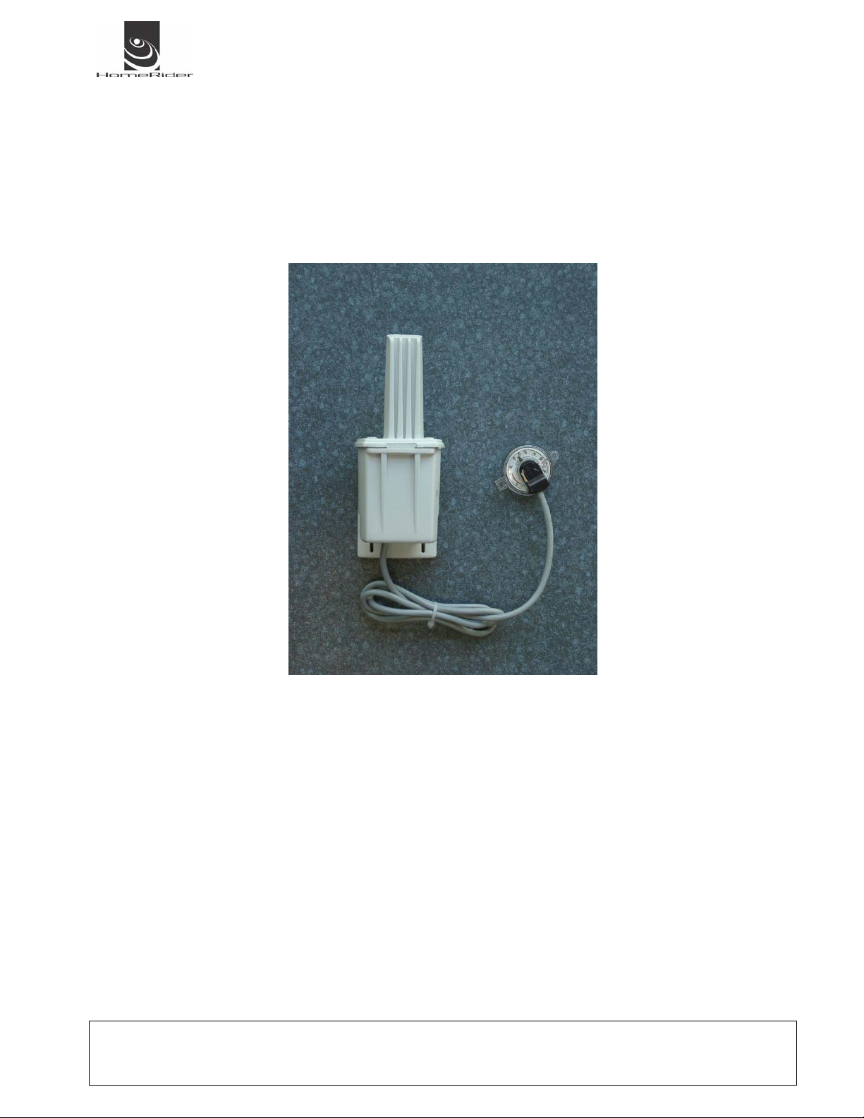
The Propane Trak Module is a system to manage the level of gas in a Tank. The module is intrinsic safety and is
designed to operate in explosive area.
The module is powered by a battery that allow 10 years of operation.
Figure 1 : Propane Trak
The module casing allow operation in various area indoor and outdoor. The Rochester gauge type used is the Junior
model. That is this system is able to replace directly the Rochester mechanical indicator witch is provided with the
tank
User Manual PROPANE TRAK Date : 07/09/2003
Reference : ADH_HRS_PROTRK_090703 V0.01
Author : Adnane Driouech - Technical Department
State : Validated Page : 4 / 13
Ce document est la propriété exclusive de HOMERIDER SYSTEMS, il ne peut être re produit ou communiqué sans son autorisation écrit e.
Page 5
2 TECHNICAL SPECIFICATIONS
2.1 Functional description
The module Propane Trak is designed to be installed on a Gas Tank equipped with a mechanical Rochester Gauge.
The module read le level on the gauge every hour and memorize it.
After 12 hour (12 reading) the module transmit a radio data frame with the level history of the last 12 hours to à
C@llRider®. A C@llRider® is another part of the system that receive the data and then connect to internet and send
the data over the net to the servers.
2.2 Hardware specifications
2.2.1 Mechanical specifications
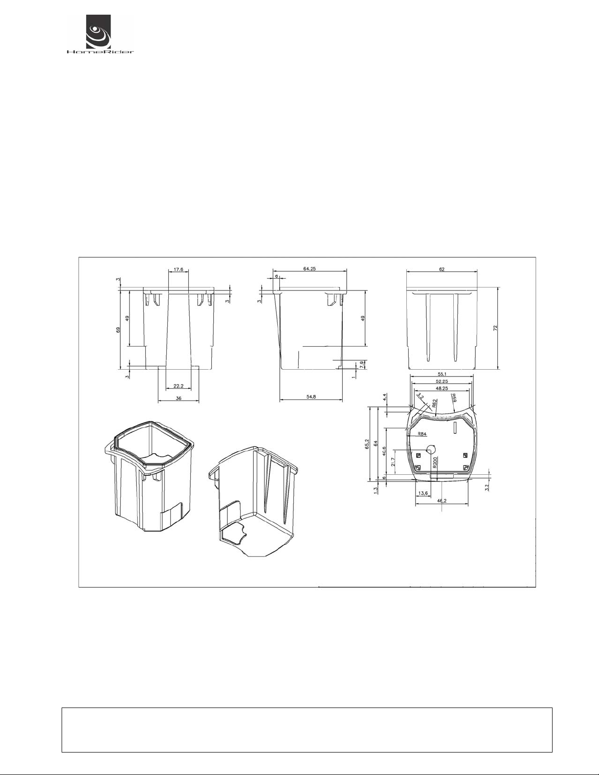
The electronic part is housed in a specific casing.
Figure 2 : Casing Bottom
Figure 3 : Casing Top
User Manual PROPANE TRAK Date : 07/09/2003
Reference : ADH_HRS_PROTRK_090703 V0.01
Author : Adnane Driouech - Technical Department
State : Validated Page : 5 / 13
Ce document est la propriété exclusive de HOMERIDER SYSTEMS, il ne peut être re produit ou communiqué sans son autorisation écrit e.
Page 6

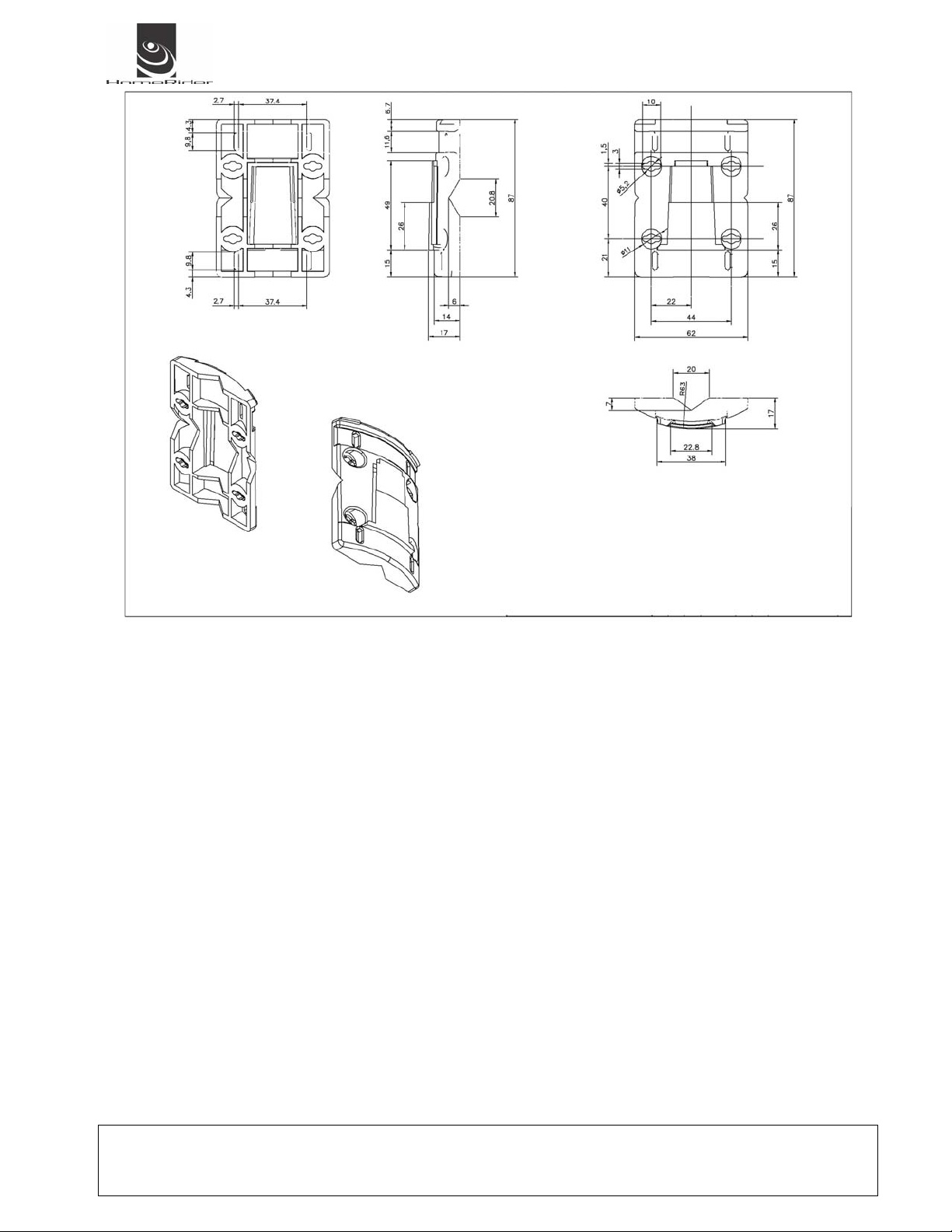
Figure 4 : Soleplate
User Manual PROPANE TRAK Date : 07/09/2003
Reference : ADH_HRS_PROTRK_090703 V0.01
Author : Adnane Driouech - Technical Department
State : Validated Page : 6 / 13
Ce document est la propriété exclusive de HOMERIDER SYSTEMS, il ne peut être re produit ou communiqué sans son autorisation écrit e.
Page 7
2.2.2 Ambient conditions
The module is designed to operate in a temperature range of –20 °C to 60 °C
2.2.3 Electrical specifications
The module is powered by a 3.6 Volts, 2,25 A/hour lithium battery.
2.2.4 Radio specifications
The radio part of the module use the 915 Mhz frequency range.
3 RF TRANSCEIVER
3.1 Protocole RF
The objective of the present chapter is to describe the 915MHz low level protocole used for the Propane Trak project.
The restrictions are:
• FCC part 15
• Low power consumption
• MSP430 family
• ATMEL Transceiver
• Range 915 -> 921.3 Mhz
User Manual PROPANE TRAK Date : 07/09/2003
Reference : ADH_HRS_PROTRK_090703 V0.01
Author : Adnane Driouech - Technical Department
State : Validated Page : 7 / 13
Ce document est la propriété exclusive de HOMERIDER SYSTEMS, il ne peut être re produit ou communiqué sans son autorisation écrit e.
Page 8

3.1.1 Presentation
At the physical level, the standard imposes an even radio power density distribution on the spectrum. The Frequency
hope spread spectrum (FHSS) scheme was retained to achieve it.
The FHSS principal is:
Transmitting on one frequency for a certain time, then pseudo-randomly jumping to another, and transmitting again.
Also, the FHSS could counter-act interference by using different carrier frequency at different time. It's carrier will hop
around within the band so that hopefully it will avoid the jammer at some frequencies.
To synchronize the transmission and reception frequency, in order to prevent lost data, a sync word has been
inserted. Also, to assure completion of all the data, an algorithm of data interleaving and data correction have been
implemented.
3.1.2 Structure
Simplified OSI structure:
------------------------------------------------------------------ HR_Interface
------------------------------------------------------------------ LLC_Interface
------- MAC_Interface
------------------------------------------------------------------ PHY_Interface
User Manual PROPANE TRAK Date : 07/09/2003
Reference : ADH_HRS_PROTRK_090703 V0.01
Author : Adnane Driouech - Technical Department
State : Validated Page : 8 / 13
7. Application Layer
Application data
6. Presentation Layer
5. Session Layer
Not used
4. Transport Layer
3. Network Layer
2. Data Link Layer
Logical Link Control Layer
Network (LF,CF,CI,)
Medium Access Control Layer
1. Physical Layer
Interleaving + BCH
CRC
Address (ISA/DA)
Transmission
Modulation
Manchester
Synchro
Compensation dérive en
fréquence
Frequency hope
Ce document est la propriété exclusive de HOMERIDER SYSTEMS, il ne peut être re produit ou communiqué sans son autorisation écrit e.
Page 9
4
3.1.3 Layer description
3.1.3.1 Physical layer
The physical layer assures the following:
• Modulation
• Manchester coding (average energy)
• Frequency hope
• Synchronization
• Compensation of frequency shift due to T° and aging
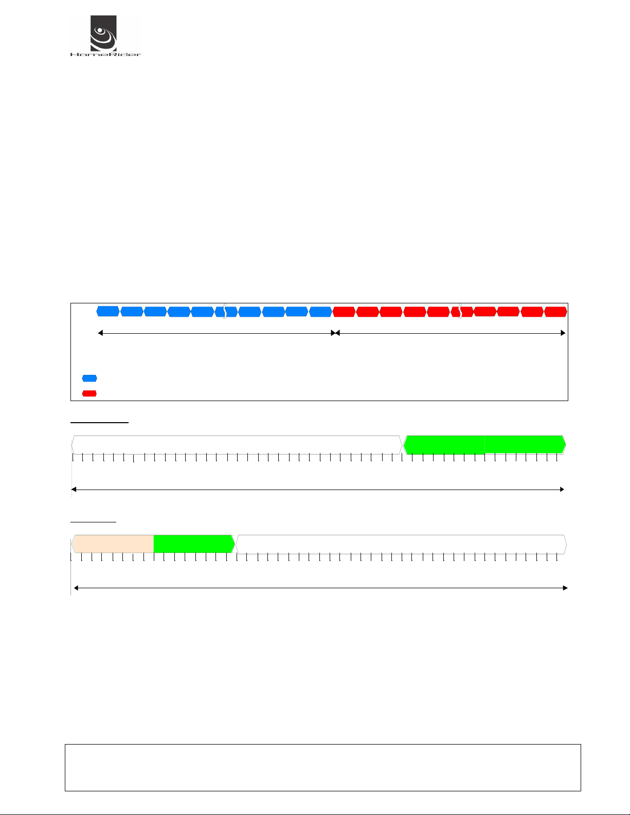
3.1.3.1.1 Frame structure
The frame is composed of 2 successive “sub-frame” of fixed length:
1/ Beacon sub-frame
The beacon sub-frame is composed of 64 bursts. Each burst consists of 48 chips (24bits). And for
each burst, there’s a frequency hope Î 64 bursts for 64 frequencies.
The beacon burst is composed of a preamble and a long sync word
2/ Data sub-frame
The data sub-frame is composed of 64 bursts. Each burst consists of 48 chips (24bits). And for
each burst, there’s a frequency hope Î 64 bursts for 64 frequencies.
The data burst is composed of a preamble, short sync word and 16 bits of data.
séquence balise séquence donnée
séquence 1 2 3 4 5 61 62 6 3 64 1 2 3 4 5 61
fréquence 5 2 63 3 35 1 2 27 4 7 20 33 5 2 63 3 35 12 27
burst balise
burst donné
Beacon Burst
pream ble 32c hips
long sy nc.p 16 chips
T.burst
Data Burst
pream ble 8chips
sy nc 8 chips
dat a 16 bit s = 3 2chip s
T.burst
User Manual PROPANE TRAK Date : 07/09/2003
Reference : ADH_HRS_PROTRK_090703 V0.01
Author : Adnane Driouech - Technical Department
State : Validated Page : 9 / 13
Ce document est la propriété exclusive de HOMERIDER SYSTEMS, il ne peut être re produit ou communiqué sans son autorisation écrit e.
Page 10
3.1.4 Hardware interface
The module is connected to the Rochester gauge by a 3 wire cable. The length of cable is 2 m.
3.2 Software specifications
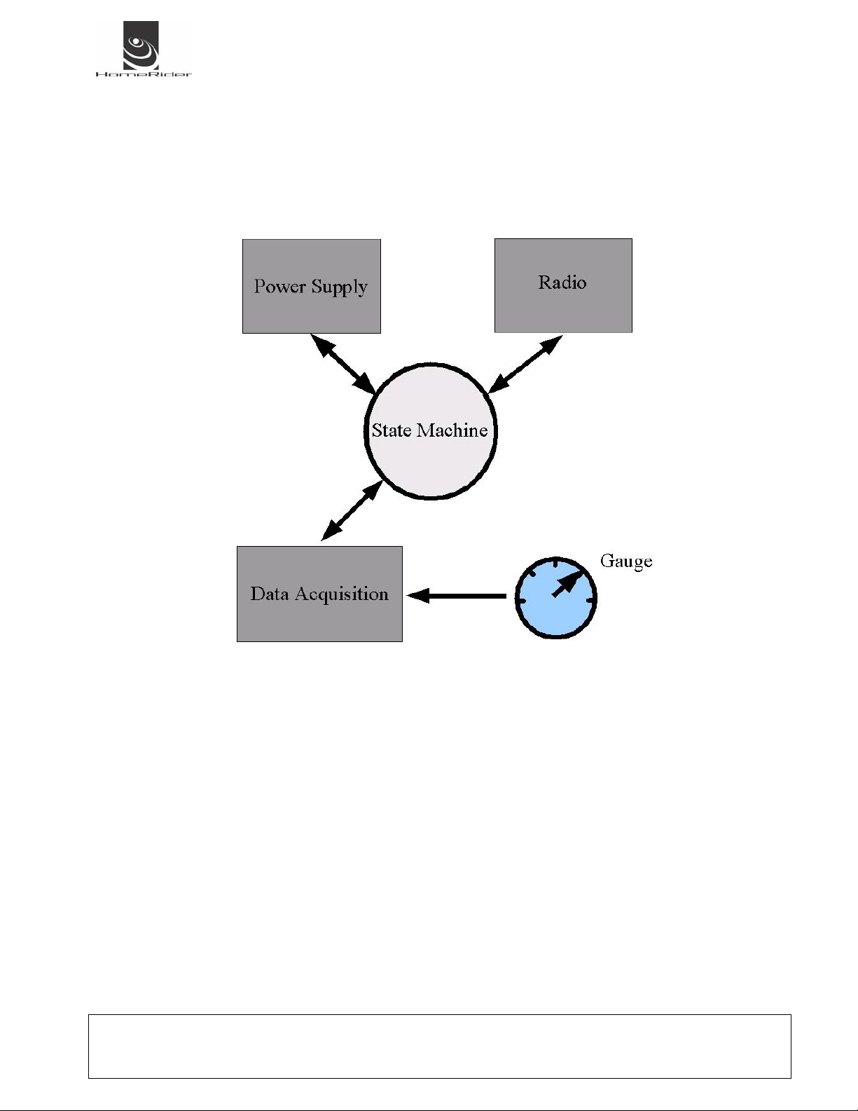
Figure 5 : Software bloc
The principle of the software is to read the gauge every hour and to memorize the value. After 12 hours, the module
activate the radio to send a data frame with the last 12 hours inside. After the system return to sleep for one hour
waiting the time for the next measure.
User Manual PROPANE TRAK Date : 07/09/2003
Reference : ADH_HRS_PROTRK_090703 V0.01
Author : Adnane Driouech - Technical Department
State : Validated Page : 10 / 13
Ce document est la propriété exclusive de HOMERIDER SYSTEMS, il ne peut être re produit ou communiqué sans son autorisation écrit e.
Page 11

4 INSTALLATION PROCESS
To install the module :
9 Fix the soleplate on the wall with 2 or more screw.
9 After having start the C@llRider® (see C@llRider® documentation)
9 place the magnet during 6 to 10 second to generate an INSTALL data radio frame.
9 Plug the module on the soleplate.
The installation is complete.
User Manual PROPANE TRAK Date : 07/09/2003
Reference : ADH_HRS_PROTRK_090703 V0.01
Author : Adnane Driouech - Technical Department
State : Validated Page : 11 / 13
Ce document est la propriété exclusive de HOMERIDER SYSTEMS, il ne peut être re produit ou communiqué sans son autorisation écrit e.
Page 12
5 PRODUCTION INFORMATION
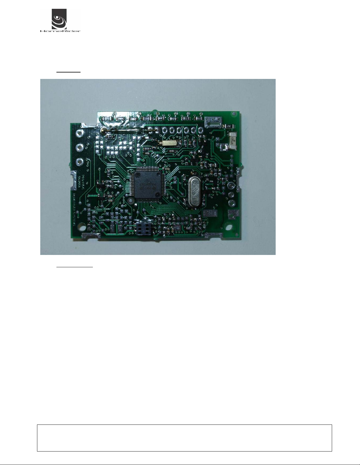
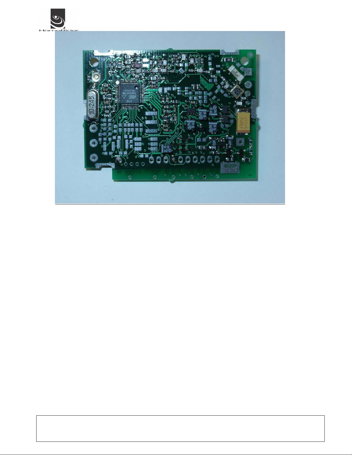
5.1 Components placement
PCB TOP
PCB BOTTOM
User Manual PROPANE TRAK Date : 07/09/2003
Reference : ADH_HRS_PROTRK_090703 V0.01
Author : Adnane Driouech - Technical Department
State : Validated Page : 12 / 13
Ce document est la propriété exclusive de HOMERIDER SYSTEMS, il ne peut être re produit ou communiqué sans son autorisation écrit e.
Page 13
6 USER INFORMATION
6.1 Information to user.
Any changes or modifications not expressly approved by the party responsible for compliance could void the user's
authority to operate the equipment.
6.2 Labelling requirements.
This device complies with part 15 of the FCC Rules. Operation is subject to the following two conditions: (1) This
device may not cause harmful interference, and (2) this device must accept any interference received, including
interference that may cause undesired operation
User Manual PROPANE TRAK Date : 07/09/2003
Reference : ADH_HRS_PROTRK_090703 V0.01
Author : Adnane Driouech - Technical Department
State : Validated Page : 13 / 13
Ce document est la propriété exclusive de HOMERIDER SYSTEMS, il ne peut être re produit ou communiqué sans son autorisation écrit e.
 Loading...