

Page 1

PLASMA CUTTING MACHINE
HOMER Plasmacut 39
OPERATING MANUAL
ALFA IN a.s © www.alfain.eu Homer Plasmacut 39 manual EN 03
Page 2

2/17
CONTENT
1. INTRODUCTION ...................................................................................... 3
2. SAFETY INSTRUCTIONS AND WARNINGS ........................................... 4
3. CONDITIONS OF USE ............................................................................. 7
4. TECHNICAL DATA ................................................................................... 8
5. MAIN PARTS OF THE MACHINE ............................................................ 9
6. ACCESSORIES ..................................................................................... 10
7. GETTING STARTED .............................................................................. 11
8. CUTTING ............................................................................................... 13
9. MAINTENANCE ..................................................................................... 15
10. STATEMENT OF WARRANTY .............................................................. 16
11. DISPOSAL ............................................................................................. 17
12. WARRANTY LIST .................................................................................. 17
ALFA IN a.s ©
www.alfain.eu
Page 3

3/17
1. INTRODUCTION
Congratulations on your new ALFA IN product. We are proud to have you as our
customer and will strive to provide you with the best service and reliability in the
industry.
This Operating Manual has been designed to instruct you on the correct use and
operation of your ALFA IN product. Your satisfaction with this product and its
safe operation is our ultimate concern. Therefore please take the time to read
the entire manual, especially the safety precautions. They will help you to avoid
potential hazards that may exist when working with this product.
Read and understand this entire manual and your employer’s safety practices
before installing, operating, or servicing the equipment. While the information
contained in this manual represents the manufacturer's best judgement, the
manufacturer assumes no liability for its use.
Machine HOMER Plasmacut 39 is designed for cutting metal on the basis of
modern technology cutting material through a thin beam plasma gas.
HOMER Plasmacut 39 is designed for high-quality cutting of materials up to 10
mm thick carbon steel (for more information, see instructions below).
At lower demands on the quality of the cut can be cut through (separate) the
material thickness to 15 mm.
We reserve the law of adjustments and changes in case of printing errors,
change of technical parameters, accessories etc. without previous notice. These
changes may not be reflected in the manuals for use in paper or electronic form.
ALFA IN a.s ©
www.alfain.eu
Page 4

4/17
2. SAFETY INSTRUCTIONS AND WARNINGS
1. OPERATION AND MAINTENANCE OF PLASMA ARC EQUIPMENT CAN
BE DANGEROUS AND HAZARDOUS TO YOURHEALTH.
2. Plasma arc cutting produces intense electric and magnetic emissions that
may interfere with the proper function of cardiac pacemakers, hearing aids,
or other electronic health equipment. Persons who work near plasma arc
cutting applications should consult their medical health professional and
the manufacturer of the health equipment to determine whether a hazard
exists.
3. Once the packing has been opened, make sure that the machine is not
damaged. If in any doubt, call the service centre.
4. This equipment must only be used by qualified personnel.
5. During installation, any electric work must only be carried out by trained
personnel.
6. The machine must be used in a dry place with good ventilation.
7. Make sure that no metal dust can be drawn in by the fan inside the
machine, as this could cause damage to the electronic circuits.
8. It is prohibited to connect more than one INVERTER generator in series or
in parallel.
9. When installing the machine, follow the local regulations on safety.
10. The position of the machine must allow easy access by the operator
to the controls and connectors.
11. When the cutting machine is operating, all its covers and doors must
be closed and well fixed.
12. Do not expose the cutting machine to direct sunlight or to heavy rain.
This equipment conforms to protection rating IP21S.
13. The operator must wear gloves, clothes, shoes, and a helmet or a
welder’s helmet, which protect and are fire-resistant in order to protect him
against electric shock, flashes and sparks from cutting.
14. The operator must protect his eyes with safety visor or mask
designed for welding, fitted with standard safety filters. He should also be
aware that during plasma cutting ULTRAVIOLET RADIATION is emitted.
Therefore it is vital that his face is also protected from radiation. Ultraviolet
rays produce the same harmful effect as sun burning on unprotected skin.
15. The operator is obliged to warn anyone near the cutting area of the
risks that cutting involves and to arrange to provide adequate protection
equipment.
16. Keep all fumes and gases from the breathing area.
17. Keep your head out of the fume plume.
18. Use an air-supplied respirator if ventilation is not adequate to remove
all fumes and gases.
19. The kinds of fumes and gases from the plasma arc depend on the
kind of metal being used, coatings on the metal, and the different
ALFA IN a.s ©
www.alfain.eu
Page 5

5/17
Antimony
Chromium
Mercury
Cadmium
Manganese
Vanadium
processes. You must be very careful when cutting or welding any metals
which may contain one or more of the following:
Nickel
Barium
Beryllium Lead
Cobalt Arsenic
Copper Selenium
Silver
20. Always read the Material Safety Data Sheets (MSDS) that should be
supplied with the material you are using. These MSDSs will give you the
information regarding the kind and amount of fumes and gases that may
be dangerous to your health.
21. It is very important to arrange for sufficient ventilation, especially
when cutting in enclosed spaces. We suggest using suitable fume
extractors to prevent the risk of intoxication by fumes or gas generated by
the cutting process.
22. Noise can cause permanent hearing loss. Plasma arc processes can
cause noise levels to exceed safe limits. You must protect your ears from
loud noise to prevent permanent loss of hearing.
23. To protect your hearing from loud noise, wear protective ear plugs
and/or ear muffs. Protect others in the workplace.
24. Noise levels should be measured to be sure the decibels (sound) do
not exceed safe levels.
25. The operator must ensure all flammable materials are removed from
the work area to avoid any risk of fire.
26. The operator must NEVER cut containers that have previously
contained petrol, lubricants, gas or similar flammable materials, even if the
container has been empty for a considerable time. THERE IS A VERY
HIGH RISK OF EXPLOSION.
27. The operator must be aware of all the special regulations which he
needs to conform to when cutting in enclosed spaces with a high risk of
explosion.
28. To prevent electric shock, we strongly suggest the following rules:
a) Do not work in a damp or humid environment.
b) Do not use the machine if its cables are damaged in any way.
c) Make sure that the earthing system of the electric equipment is correctly
connected and operational.
d) The operator must be insulated from the metal components connected
to the return wire.
e) The earthing of the piece being worked could increase the risk of injury
to the operator.
29. EN 60974-1 Standard: Open-circuit voltage. During the operation of
the machine, the highest voltage, with which it is possible to come into
ALFA IN a.s ©
www.alfain.eu
Page 6

6/17
S
contact, is the open-circuit voltage between the clamps. In our generator
this voltage is 260V.
30. The maximum open-circuit voltage of the plasma machines is
established by national and international standards (EN 60974-1)
depending on the type of current to be used, on its waveform and on the
hazards arising from the work place. These values are not applicable to
the strike currents and those for stabilisation of the arc that could be above
it.
31. The open-circuit voltage, for as many adjustments as possible, must
never exceed the values relating to the various cases shown in the
following table:
Case Working conditions Open-circuit voltage
1
2
3
4 Plasma cutting
32. In case 1, the dc machines with rectifier must be built in such a way
Places with increased risk of
electric shock
Places without increased risk
of electric shock
Torches held mechanically
with increased protection for
the operator
that, in case of a fault developing in the rectifier (for example open circuit,
short circuit or lack of power), the permitted values cannot be exceeded.
The plasma cutting machines of this type can be marked with the symbol:
DC current: 113V
peak value
DC current: 113V
peak value
DC current: 141V
peak value
DC current: 500V
peak value
AC current: 68V
peak value and
48V effective
AC current: 113V
peak value and
80V effective
AC current: 141V
peak value and
100V effective
33. Before opening the machine switch off the machine and disconnect
it from the power socket.
34. Only personnel authorised by this company can carry out
maintenance on the machine.
PROTECTIVE UTTILITIES
1. Welding helmet with filter shade at least 10
2. Welding gloves
3. Welding apron and cloth
4. Welding boots
ALFA IN a.s ©
www.alfain.eu
Page 7

7/17
RISK OVERVIEW
1. Risk of electric shock
2. Ultraviolet light and light radiation
3. Risk of inhaling gas fumes and dust particles
4. Burns
5. Noise
NOTE
1. It is forbidden to operate a machine with damaged insulation of the cutting
torch or supply cable.
2. Never operate the machine taken down or damaged covers.
3. It is forbidden to operate the machine in wet environments and outdoors in
rain or snow.
4. Ensure proper grounding clamping pliers, which also reduces the risk of
electric shock.
5. Use prescribed protective utilities, keep them dry.
6. Plasma arc cutting produces intense electric and magnetic emissions that
may interfere with the proper function of cardiac pacemakers, hearing aids,
or other electronic health equipment. Persons who work near plasma arc
cutting applications should consult their medical health professional and
the manufacturer of the health equipment to determine whether a hazard
exists.
7. Never aim the torch against the eyes, body or other person.
3. CONDITIONS OF USE
1. This equipment must only be used by qualified personnel.
2. During installation, any electric work must only be carried out by trained
personnel.
3. Device complies with IEC 61000-3-12.
4. Do not expose the plasma machine to direct sunlight or to rain or snow.
This equipment conforms to protection rating IP21S.
5. Working ambient temperature between -10 and +40 °C.
6. Relative humidity below 90% at +20 °C.
7. Up to 3000 m altitude.
8. Place the machine the way that the cooling air can enter the vents without
restriction to. It is necessary to ensure that no impurities, especially metal
particles, are not drawn into the machine.
9. Cutting machine in terms of interference suppression is intended primarily
for industrial premises. In the case of use of other areas may be need for
special measures (see EN 60974-10).
10. The machine must be protected against
a. Moisture and rain and snow
b. Mechanical damage
ALFA IN a.s ©
www.alfain.eu
Page 8

8/17
(separate mat.)
c. Draft and any ventilation of neighbouring machine
d. Excessive overloading - crossing technical parameters
e. Rough handling
ELECTROMAGNETIC COMPATIBILITY
The welding device is in terms of interference designed primarily for industrial
areas. It meets the requirements of EN 60974-10 class A and it isn’t designed
for using in residential areas, where the electrical energy is supplied by public
low-voltage power supply network. It can be here potential problems with
ensuring of electromagnetic compatibility in this areas, due to interference
caused by power lines as well as the radiated interference.
During operation, the device may be the source of interference.
Caution
We warn users, that they are responsible for possible interference from welding.
4. TECHNICAL DATA
Method Plasma cutting
Mains voltage V/Hz 1 x 230/50-60
Cutting current range A 20 - 40
Open-circuit voltage U20 V 260
Mains protection A 16 @
Max. effective current I
Cutting current (DZ=100%) I2 A 20
Cutting current (DZ=60%) I2 A 26
Cutting current (DZ=x%) I2 A 25%=40
Max. cutting thickness - carbon steel
Carbon steel mm 10
Quality cutting
thickenss
Max. input pressure bar 8,5
Stainless steel mm 7
Aluminium mm 5
Copper mm 3
A 14,8
1eff
mm 15
Working pressure (torch Parker SCB 50) bar 4,0
Air consumption (torch Parker SCB 50) l/min 120
Arc ignition HF
Current regulation continuous
Protection IP 21S
Standards EN 60974-1, EN 60974-10 cl. A
Dimensions (w x l x h) mm 170 x 480 x 315
ALFA IN a.s ©
www.alfain.eu
Page 9
9/17
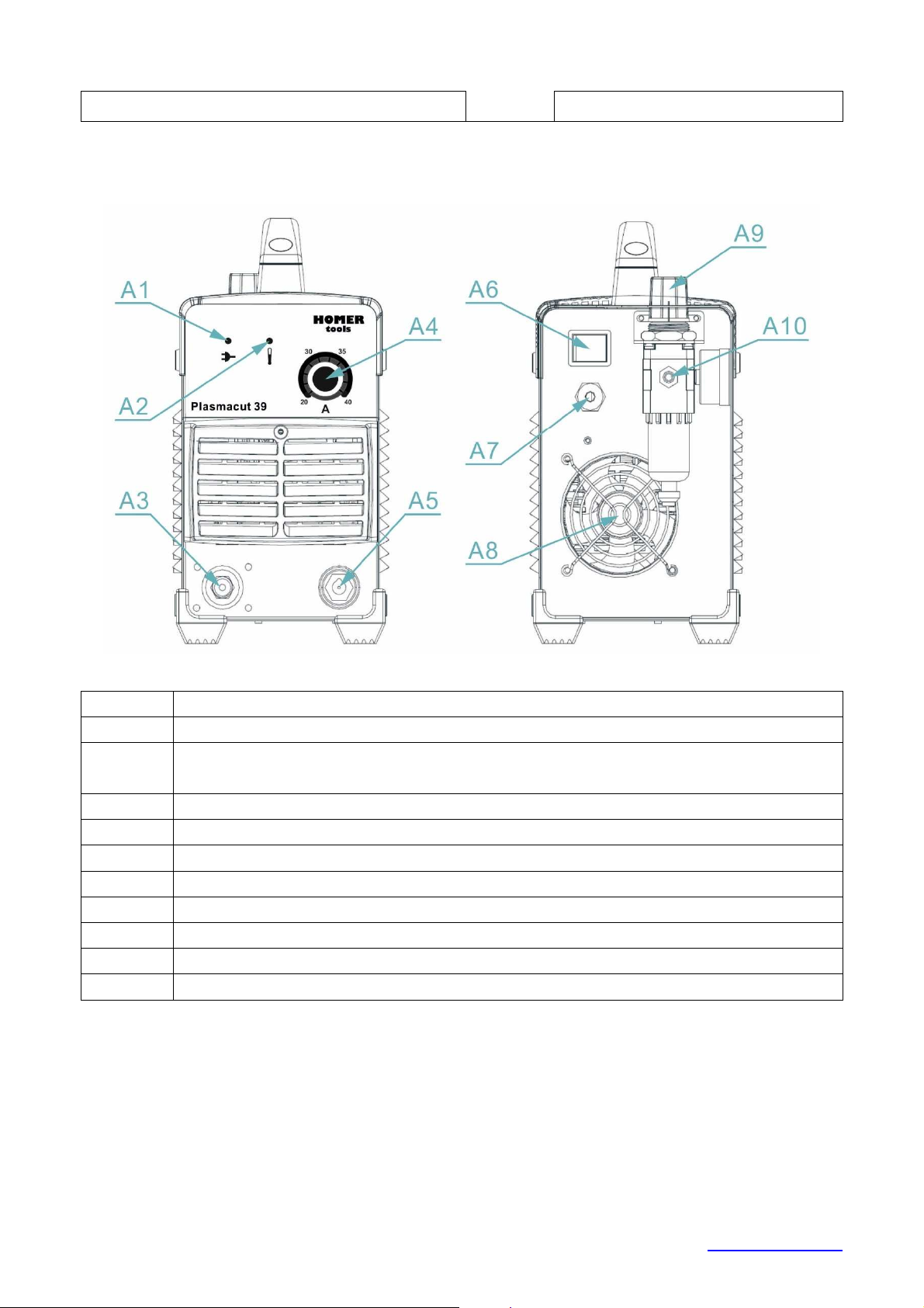
Pos. Description
A1 LED
indicator
– when i
lluminated, the machine is ON
disconnected. In such a case leave the machine on to cool down.
A3 Cutting torch
A4 Poten
t
iomet
er of cutting current setting
A5 Earthing cable
A6 Switch
ON/OFF
A7 Mains cable
A8 Fan
A9 Oil water separator with manometer
A10
Gas fitting
Weight (including torch) kg 9,4
5. MAIN PARTS OF THE MACHINE
FRONT AND REAR PANELS
Fig. 1 – Main parts of the machine
A2
LED indicator. If the LED illuminates the thermo-switch is
ALFA IN a.s ©
www.alfain.eu
Page 10
10/17
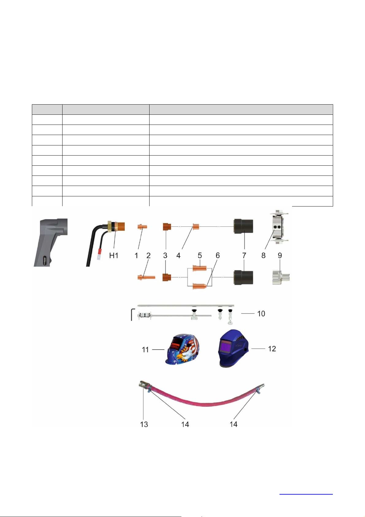
Pos. Code
Description
SCB50
-40-
M16X1.5
Torch
Plasma SCB50 Homer 4 m (
substitute
)
10 P166
Circle Cutting Attachment SCB50
23 4801
Adapter hoses for filter AT 1000
24 5302
Air Filter AT 1000
25 5304
Adapter for AT 1000 PEGAS PLASMA
11 S777c.
Welding Helmet Barracuda S777C Black
12 S7SUN9B
Welding Helmet S9B Shooting Blue Shark
13 E700008
Quick Connector SK
-
NW7,2
-
9 mm for hose
14 2546
Clamp 10
-
16 Gemi
6. ACCESSORIES
CONTENT OF DELIVERY
1. Torch Plasma SCB50 Homer 4 m
2. Earthing cable
3. Operating manual
ON REQUEST
Fig. 2 – Spare parts of the torch SCB 50, machine and adapter
ALFA IN a.s ©
www.alfain.eu
Page 11

11/17
Pos. Code
Description
H1 5052
O-
Ring PT
-
60, SCP 60
1 P1521
-Hf
Electrode Hafnium SCB50
2 P1518
-Hf
Electrode Hafnium Extended SCB50
3 P1510
Swirl Ring SCB50
4 P1304
Cutting Tip 1,0 Standard SCB50
5 P1370
Cutting Tip 1,0 Extended SCB50
6 P1306
Cutting Tip 1,0 Contact Extended SCB50
7 P5.710.121
Retaining Cap
SCB50
8 P154
Cutting Buggy SCB50
9 P1394S
-50
Shield Cap Hand SCB50
Pos. Code
Description
pc
6096
Starting Kit for SCB50 Homer 4 m
Content of starting kit
6096
1 P1521
-Hf
Electrode Hafnium SCB50
2
4 P1304
Cutting Tip 1,0 Standard SCB50
4
SCB50
9 P1394S
-50
Shield Cap Hand SCB50
1
Note – the bold items are equipped on the torch
Recommended starting kit for the Torch SCB 50:
2 P1518-Hf
6 P1306
Electrode Hafnium Extended
1
SCB50
Cutting Tip 1,0 Contact Extended
2
7. GETTING STARTED
Getting started must be consistent with technical data and conditions of use.
NOTE This equipment must only be used by qualified personnel.
1. Before beginning work is necessary to connect the machine to the mains
(1x230V, 50-60 Hz) in accordance with the chapter 4. TECHNICAL DATA.
2. Check completeness of the mounted cutting torch.
3. Connect the compressed air quick connector to the connector A10 on the
rear wall of the machine.
4. Connect the earthing cable to the cutting material.
5. Check the input pressure. The max. input pressure is 8,5 bar and the min.
input pressure is 4,0 bar.
6. Switch the main switch A6 to the ON position, LED A1 on the control panel
will shine.
7. By means of the potentiometer A4 set the cutting current corresponding to
the thickness of the cutting material.
ALFA IN a.s ©
www.alfain.eu
Page 12
12/17
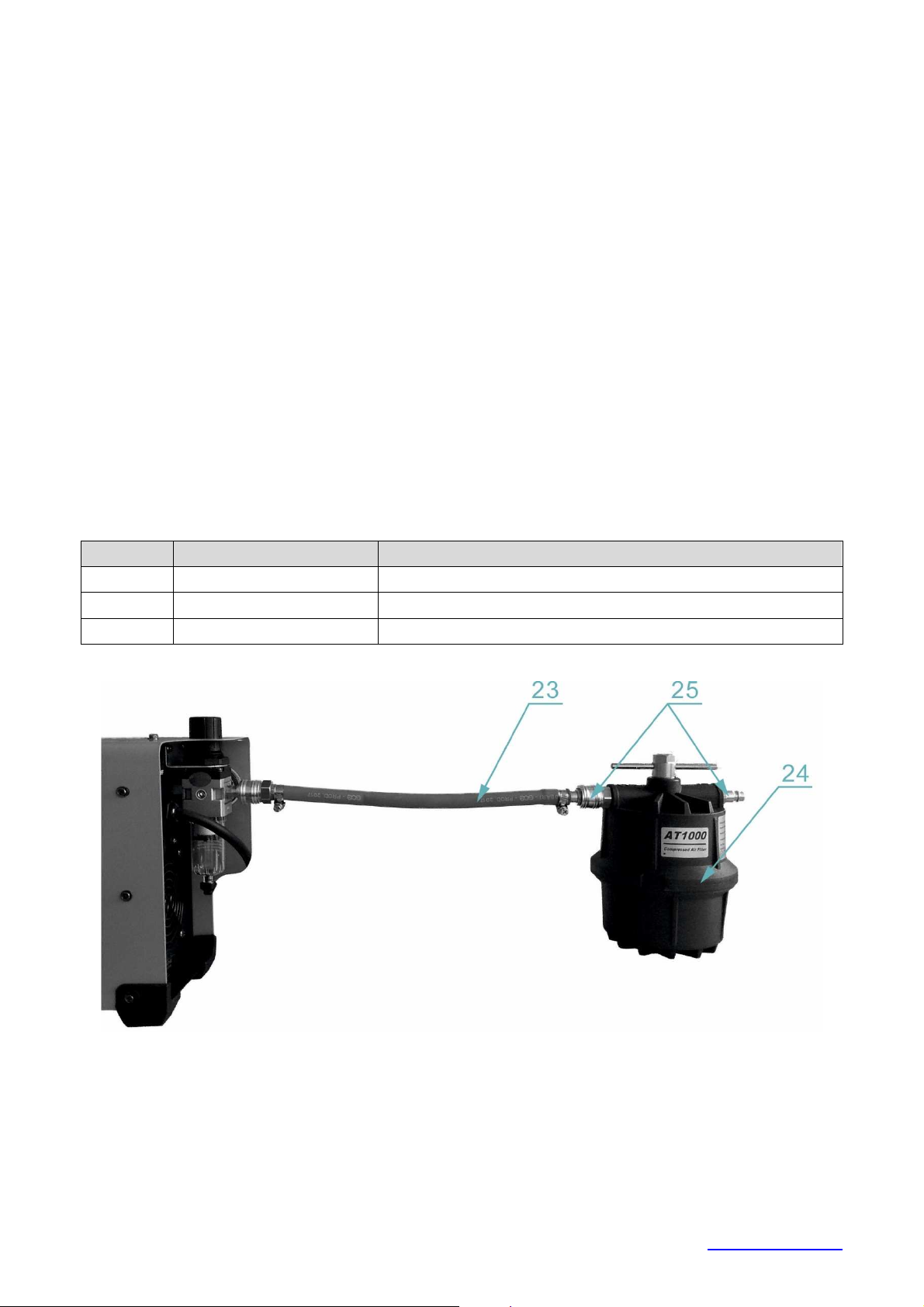
Pos. Code
Description
23 4801
Adapter hoses for filter AT 1000
25 5304
Adapter for AT
1000 PEGAS PLASMA
8. Press the torch trigger and check, eventually set the working pressure to
4,0 bar on the regulator A9.
REQUIREMENTS FOR SOURCE OF COMPRESSED AIR
1. Delivered air pressure must be max. 8,5 bar and min. 4,0 bar.
2. Air consumption 140 l/min.
3. Compressed air for the plasma must be clean and dry.
4. Pressure dew point +3 °C.
5. Maximum oil content 0.1 mg/m3.
6. Maximal size of solid particles 15 microns.
7. The sufficient size of an air tank is 25 l.
8. No additional oiling if the pressure air is permitted. That could damage the
plasma machine and the cutting torch.
OPTIONAL AIR FILTERS FOR HOMER PLASMACUT 39
To achieve high quality cutting and to avoid serious disturbances to the torch it
is highly advised to include the air filter. The filter needs to be connected to the
machine by means of the hoses adapter.
24 5302 Air Filter AT 1000
Fig. 3 – Air filter AT 1000
ALFA IN a.s ©
www.alfain.eu
Page 13
13/17
8. CUTTING
1. Move the torch to the material and press the torch trigger. The arc will
ignite.
2. Start with cutting. After end of cutting release the torch trigger, the arc turns
off and for 30 seconds the air will flow to cool down the torch.
3. After end of pre-gas procedure/torch cooling, which lasts 30 seconds, you
can turn off the machine.
4. Move the torch with a constant speed. Cutting speeds vary according to
torch output amperage, the type of material being cut, and operator skill.
5. Output current setting or cutting speeds may be reduced to allow slower
cutting when following a line, or using a template or cutting guide while still
producing cuts of excellent quality.
6. To achieve a good cutting quality make sure the distance between the tip
and the material is max. 2 mm. At a greater distance decreases cutting
power and the arc may go off. The nozzle can be pulled directly on the
material.
7. Plasma cutting may be done in all possible positions (vertically,
horizontally, overhead, vertical ascending and descending), but as far as
possible choose primarily horizontal cut. In other positions the operator is
increasingly threatened by flying drops of molten material.
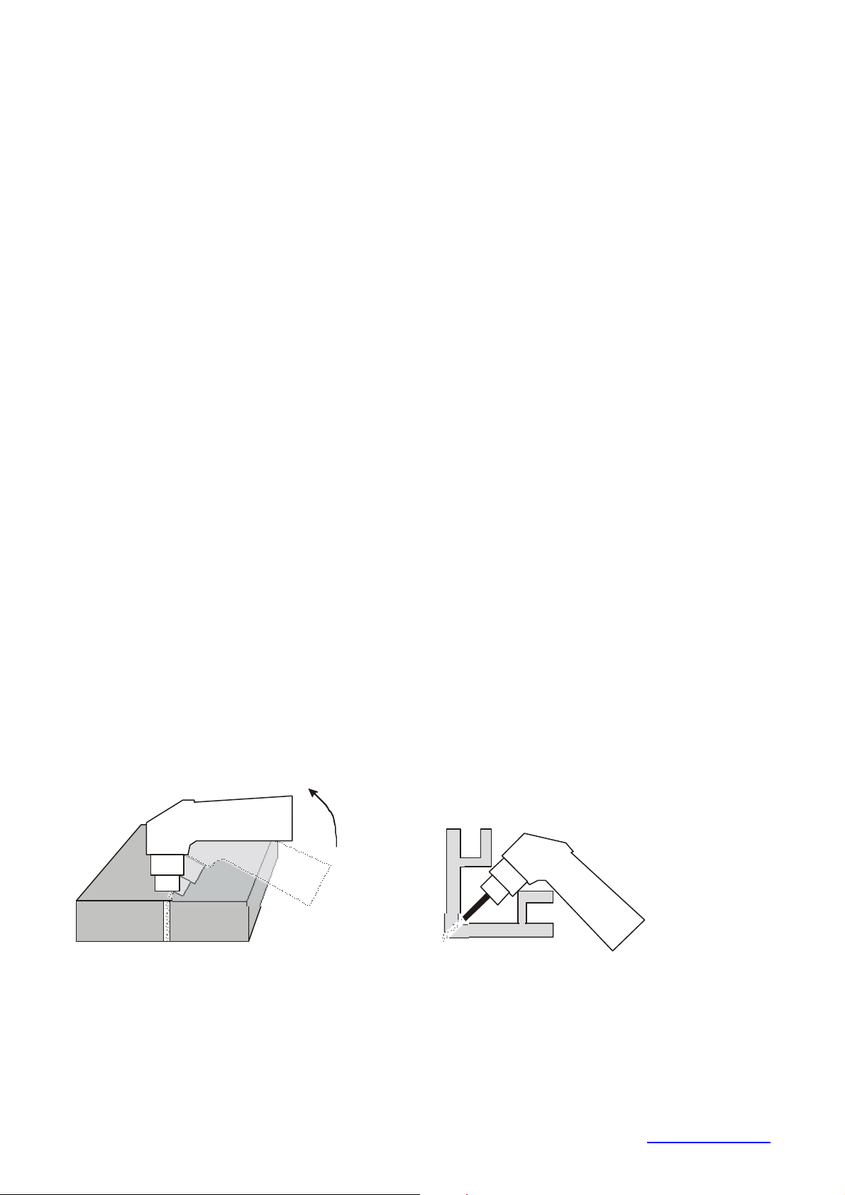
8. We recommend starting cutting at the edge of the material. If needed to
start from the centre of the material, or to cut hole into the material, slightly
tilt the torch head and gradually it straighten into a vertical position so the
spraying material would not damage the cutting tip (see Figure 4). This
workflow must always be followed, if the thickness of material is above 3
mm.
9. In case of cutting in the corner or around the corner (see Figure 5), use the
long electrode and cutting tip. The cutting power while using the Long
cutting tip is decreased.
Fig. 4 Fig. 5
ALFA IN a.s ©
www.alfain.eu
Page 14

14/17
IMPORTANT RULES
1. The pilot arc burning time should be limited only to the time necessary. It
lowers the wear of the cutting tips and electrodes.
2. Never turn off the main switch immediately after finishing cutting but
always leave time to run cooling cycle to cool down the torch. Immediate
turn-off only in case of emergency.
3. Ensure a good el. contact of the work lead clamps and cutting material.
4. Check and timely exchange cutting tips and the electrodes. Lifetime of
these parts is highly dependent on compliance with the principles of good
cutting.
5. Disconnect the machine from the mains before replacing the torch
consumable parts.
6. Unplug the machine from the mains before any intervention inside the
machine.
7. In case of low air pressure or disconnected air input never press the torch
trigger. It can cause the torch damage.
8. HOMER Plasmacut 39 is adapted for use with torch SCB 50. This
combination comply with EN 60974-7 Article 10.1.4. Using any other type
and design of a torch must be approved by ALFA IN a.s.
9. Imperfect capture of condensate would cause its elimination in the area of
the cutting tip and it would prevent ignition of the pilot arc.
SOURCES OF POOR QUALITY CUTS
Shallow penetration of the cut
1. The cutting speed is too high. Make sure the slope of the cutting arc does
not exceed about 15° (see Figure 6).
2. High wear of the cutting tip or electrode (see Figure 7).
3. Too large thickness of material and not adequately chosen value of current
and diameter of the cutting tip.
4. Bad contact between the work lead clamps and material.
Cutting arc is unstable, goes off and "shoots"
1. Worn out cutting tip or electrode
2. High pressure
3. Impurities in the pressure air
4. not captured water condensate
Conical cut
1. If there is a false cut (see Figure 8) turn off the machine, release the shield
cup and rotate the cutting tip about 1/4 and again try to cut.
2. Damaged cutting tip and electrode.
3. The position of the torch is not perpendicular to the material.
4. Too large distance from the cutting tip to the material.
ALFA IN a.s ©
www.alfain.eu
Page 15

15/17
o
Max 15
Fig. 6 Fig. 7 Fig. 8
9. MAINTENANCE
1. A great care should be taken to the cutting torch. The molten material
sprays while cutting. This sputter contaminates the interior space of the
torch. The worn parts (consumables) of a plasma torch should be regularly
maintained and timely exchanged. Regularly check the condition of
diffuser channels (see diagram of the torch). If contaminated, you must
clean it with a pressure air or to replace the diffuser. Poor state of the
diffuser has a negative impact on the quality of cutting and causes very
strong interference that may cause the collapse of the machine control
electronics or influence the surrounding devices. If the cable bundle of the
torch is worn out it must be replaced immediately - danger of electrical
shock.
2. Disconnect the HOMER from the mains supply voltage before
disassembling.
3. Special maintenance is not necessary for the control unit parts in the
plasma cut machine. If these parts are damaged for any reason,
replacement is recommended.
CAUTION
4. Do not blow air into the plasma cut during cleaning. Blowing air into the
plasma cut can cause metal particles to interfere with sensitive electronic
components and cause damage to the welder.
5. To clean the plasma cut, disconnect it from the mains supply voltage then
open the enclosure and use a vacuum cleaner to remove any accumulated
dirt and dust. The plasma cut should also be wiped clean. If necessary,
solvents that are recommended for cleaning electrical apparatus may be
used.
6. Troubleshooting and repairing of HOMER equipment should only be
carried out only by suitably qualified or competent person.
7. A ‘competent person’ must be a person who has acquired through training,
qualification or experience, or a combination of them, the knowledge and
ALFA IN a.s ©
www.alfain.eu
Page 16

16/17
skills enabling that person to safely carry out a risk assessment and repairs
to the electrical equipment in question.
8. The person carrying out the servicing needs and repairs must know what
to look at, what to look for and what to do.
10. STATEMENT OF WARRANTY
1. In accordance with the warranty periods stated below, ALFA IN guarantees
the proposed product to be free from defects in material or workmanship
when operated in accordance with the written instructions as defined in
this operating manual.
2. ALFA IN products are manufactured for use by commercial and industrial
users and trained personnel with experience in the use and maintenance
of electrical welding and cutting equipment.
3. ALFA IN will repair or replace, at its discretion, any warranted parts or
components that fail due to defects in material or workmanship within the
warranty period. The warranty period begins on the date of sale to the end
user.
4. If warranty is being sought, please contact your ALFA IN product supplier
for the warranty repair procedure.
5. ALFA IN warranty will not apply to:
a. Equipment that has been modified by any other party other than
ALFA IN’s own service personnel or with prior written consent
obtained from ALFA IN Service Department.
b. Equipment that has been used beyond the specifications established
in the operating manual.
c. Installation not in accordance with the installation/operating manual.
d. Any product that has been subjected to abuse, misuse, negligence
or accident.
e. Failure to clean and maintain (including lack of lubrication,
maintenance and protection), the machine as set forth in the
operating, installation or service manual.
6. Within this operating manual are details regarding the maintenance
necessary to ensure trouble free operation.
7. Validity condition of warranty is, that the cutting machine must be used
only with the torch, which is said in this manual.
NOTE
8. Warranty repairs must be performed by either an ALFA IN Service Centre,
an ALFA IN distributor or an Authorised Service Agent approved by the
company ALFA IN.
9. As a warranty list serves proof of purchase (invoice) on which is the serial
number of the machine, eventually a warranty list on the last page of this
manual.
ALFA IN a.s ©
www.alfain.eu
Page 17

17/17
and year of sale:
11. DISPOSAL
Only for EU countries. Do not dispose of electric tools together
with household waste material.
In accordance with European Council Directive 2002/96/EC on
electrical and electronic equipment waste and its
implementation in accordance with national law, electric tools
that have reached the end of their service life must be collected
separately and returned to an environmentally compatible
recycling facility.
12. WARRANTY LIST
As a warranty list serves proof of purchase (invoice) on which is the serial
number of the machine, eventually a warranty list below, which is filled in by an
authorized dealer.
Serial number:
Day, month (written in words)
Stamp and dealer signature:
ALFA IN a.s ©
www.alfain.eu
 Loading...