

Page 1
Montage- und
Bedienungsanleitung
Mounting instruction and
operating manual
Regensensor S. 2
Rain Sensor p. 33
HmIP-SRD
Page 2

Lieferumfang
Anzahl Bezeichnung
1 Homematic IP Regensensor
2 Montagehalterungen
2 Dübel 5 mm
2 Schrauben 3,0 x 30 mm
2 Kabelbinder
1 Torxschlüssel
1 Beiblatt mit Sicherheitshinweisen
1 Bedienungsanleitung
Dokumentation © 2020 eQ-3 AG, Deutschland
Alle Rechte vorbehalten. Ohne schriftliche Zustimmung des
Herausgebers darf diese Anleitung auch nicht auszugsweise in
irgendeiner Form reproduziert werden oder unter Verwendung
elektronischer, mechanischer oder chemischer Verfahren vervielfältigt oder verarbeitet werden.
Es ist möglich, dass die vorliegende Anleitung noch drucktechnische Mängel oder Druckfehler aufweist. Die Angaben in dieser
Anleitung werden jedoch regelmäßig überprüft und Korrekturen
in der nächsten Ausgabe vorgenommen. Für Fehler technischer
oder drucktechnischer Art und ihre Folgen übernehmen wir keine
Haftung.
Alle Warenzeichen und Schutzrechte werden anerkannt.
Printed in Hong Kong
Änderungen im Sinne des technischen Fortschritts können ohne
Vorankündigung vorgenommen werden.
154918
Version 1.0 (04/2020)
Page 3
1
A
B
C
E
D
C
Page 4
2
F
G
H
3
4x
Page 5
4
2
1
1
2
5
1
2
15 cm
Page 6
6
1
2
7
Page 7

8
9
A
+ / ~
DC- / AC-IN
B
+ / ~
DC- / AC-IN
/ ~
/ ~
Page 8
2x
10
HAP
Homematic IP
11
Page 9
12
2x
1
2
Page 10
13
2x
1
2
Page 11
14
1
4
2x
2
3
Page 12
15
4 s
16
4 s
Page 13

Inhaltsverzeichnis
1 Hinweise zur Anleitung ................................................. 14
2 Gefahrenhinweise .......................................................... 14
3 Funktion und Geräteübersicht ....................................16
4 Allgemeine Systeminformationen .............................. 17
5 Inbetriebnahme .............................................................. 17
5.1 Auswahl der Spannungsversorgung ................................ 17
5.2 Spannungsversorgung herstellen.....................................18
5.3 Anlernen ............................................................................... 20
5.4 Montagehinweise ............................................................... 22
5.4.1 Montage an ebenen Flächen ............................... 24
5.4.2 Montage an einem runden Gegenstand ........... 25
6 Fehlerbehebung .............................................................26
6.1 Befehl nicht bestätigt ......................................................... 26
6.2 Duty Cycle ........................................................................... 26
6.3 Fehlercodes und Blinkfolgen ............................................27
7 Wiederherstellung der Werkseinstellungen ..............29
8 Wartung und Reinigung ............................................... 30
9 Allgemeine Hinweise zum Funkbetrieb .................... 30
10 Technische Daten ..........................................................31
13
Page 14
Hinweise zur Anleitung
1 Hinweise zur Anleitung
Lesen Sie diese Anleitung sorgfältig, bevor Sie Ihre
Homematic IP Geräte in Betrieb nehmen. Bewahren Sie
die Anleitung zum späteren Nachschlagen auf! Wenn Sie
das Gerät anderen Personen zur Nutzung überlassen,
übergeben Sie auch diese Anleitung.
Benutzte Symbole:
Achtung!
Hier wird auf eine Gefahr hingewiesen.
Hinweis.
Dieser Abschnitt enthält zusätzliche wichtige Informationen!
2 Gefahrenhinweise
Das Gerät enthält keine durch den Anwender zu
wartenden Teile. Im Fehlerfall lassen Sie das Gerät
von einer Fachkraft prüfen.
Bei Sach- oder Personenschäden, die durch unsachgemäße Handhabung oder Nichtbeachten
der Gefahrenhinweise verursacht werden, übernehmen wir keine Haftung. In solchen Fällen erlischt jeder Gewährleistungsanspruch! Für Folgeschäden übernehmen wir keine Haftung!
14
Page 15
Gefahrenhinweise
Aus Sicherheits- und Zulassungsgründen (CE) ist
das eigenmächtige Umbauen und/oder Verändern des Gerätes nicht gestattet.
Das Gerät ist kein Spielzeug! Erlauben Sie Kindern
nicht damit zu spielen. Lassen Sie das Verpackungsmaterial nicht achtlos liegen. Plastikfolien/
-tüten, Styroporteile etc. können für Kinder zu
einem gefährlichen Spielzeug werden.
Verwenden Sie das Gerät nicht, wenn es von außen erkennbare Schäden, z. B. am Gehäuse oder
an den Bedienelementen bzw. eine Funktionsstörung aufweist. Lassen Sie das Gerät im Zweifelsfall
von einer Fachkraft prüfen.
Das Gerät ist für den Einsatz im Umfeld von
Wohnbereichen, Geschäfts- und Gewerbebereichen sowie in Kleinbetrieben bestimmt.
Jeder andere Einsatz, als der in dieser Bedienungsanleitung beschriebene, ist nicht bestimmungsgemäß und führt zu Gewährleistungs- und
Haftungsausschluss.
15
Page 16

Funktion und Geräteübersicht
3 Funktion und Geräteübersicht
Der Homematic IP Regensensor erkennt über die integrierte Sensorfläche bereits kleinste Mengen von Regen oder
Schnee. Bei einsetzendem Niederschlag übermittelt er diese
Information an angelernte Homematic IP Geräte sowie die
Homematic IP Smartphone-App. So kann zum Beispiel die
Markise in Verbindung mit einem HomematicIP Rollladen
aktor automatisch eingefahren werden. Über die Warnung
in der App und eine Push-Nachricht auf dem Smartphone
kann bei Regen schnell reagiert werden, um mögliche Schä
den bspw. durch geönete Dachfenster zu vermeiden.
Eine integrierte Sensorheizung sorgt dafür, dass die Sensoroberfläche unverzüglich trocknet. Damit werden
Funktionseinschränkungen durch Tau- und Eisbildung
verhindert. Dank des großen Temperaturbereichs und des
wassergeschützten Gehäuses (IP44) ist der Einsatz auch
unter extremen Bedingungen von -20 bis +55 °C möglich.
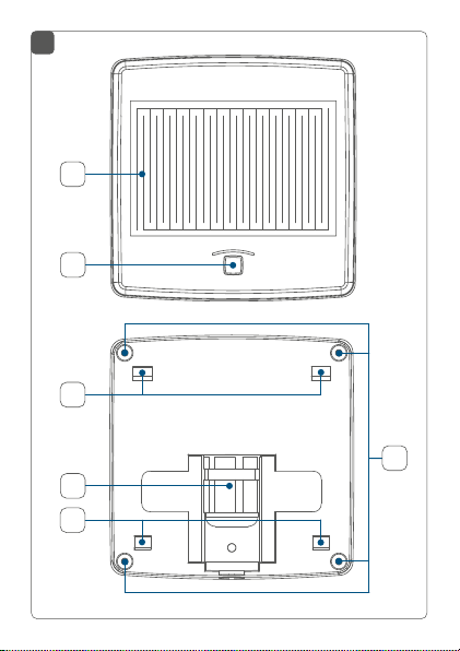
Geräteübersicht (s. Abbildung 1+2):
(A) Sensorfläche
(B) Systemtaste (Anlerntaste und LED)
(C) Verrastungen für Montagehalterungen
(D) Kabelverschraubung für die Anschlussleitung
(E) Verschraubungen Gehäusedeckel
(F) Zubehör: Montagehalterung 45 Grad
(G) Zubehör: Montagehalterung 0 Grad
(H) Kabeldurchführung (optional)
16
-
-
Page 17

Allgemeine Systeminformationen
4 Allgemeine Systeminformationen
Dieses Gerät ist Teil des Homematic IP Smart-HomeSystems und kommuniziert über das Homematic IP
Funkprotokoll. Alle Geräte des Systems können komfortabel und individuell per Smartphone über die Homematic IP App konfiguriert werden. Alternativ haben Sie
die Möglichkeit, Homematic IP Geräte über die Zentrale CCU2/CCU3 oder in Verbindung mit vielen Partnerlösungen zu betreiben. Welcher Funktionsumfang
sich innerhalb des Systems im Zusammenspiel mit weiteren Komponenten ergibt, entnehmen Sie bitte dem
Homematic IP Anwenderhandbuch. Alle technischen
Dokumente und Updates finden Sie stets aktuell unter
www.homematic-ip.com.
5 Inbetriebnahme
5.1 Auswahl der Spannungsversorgung
Die Spannungsversorgung des Regensensors erfolgt über
ein separates Netzteil (nicht im Lieferumfang enthalten).
Die Basisanforderungen für dieses Netzteil sind:
• Sicherheits-Schutzkleinspannung (SELV)
• Spannung: 10-19 V
AC/50 Hz (mind. 400 mA)
12V
• Leitungslänge max. 30 m (mind. 0,2 mm)
DC (mind. 320 mA) oder
17
Page 18

Inbetriebnahme
5.2 Spannungsversorgung herstellen
Zur Gewährleistung der elektrischen Sicherheit
muss es sich bei der speisenden Quelle um eine
Sicherheits-Schutzkleinspannung handeln.
Beachten Sie die auf dem Gerät angegebene Abisolierlänge der anzuschließenden Leiter.
Zugelassene Leitungsquerschnitte zum Anschluss an den
Regensensor sind:
Starre Leitung [mm2] Flexible Leitung ohne
0,2-1,5 0,2-1,5
Um den Regensensor ins Homematic IP System integrieren zu können, müssen Sie ihn zunächst über ein geeignetes Netzteil mit Spannung versorgen. Gehen Sie dazu
wie folgt vor:
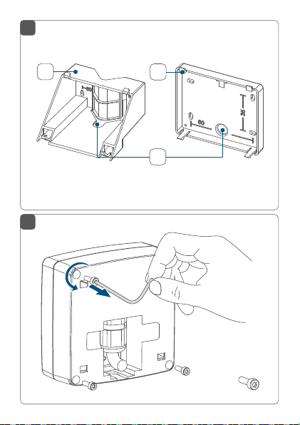
• Lösen Sie die vier Schrauben (E) auf der Rückseite
des Gehäuses mit dem beiliegenden Torxschlüssel (s. Abbildung 3).
• Nehmen Sie den Gehäusedeckel ab.
• Brechen Sie bei Bedarf die vorperforierte Kabeldurchführung, um die Montage zu erleichtern
und anschließend die Leitung des Netzteils hindurchzuführen.
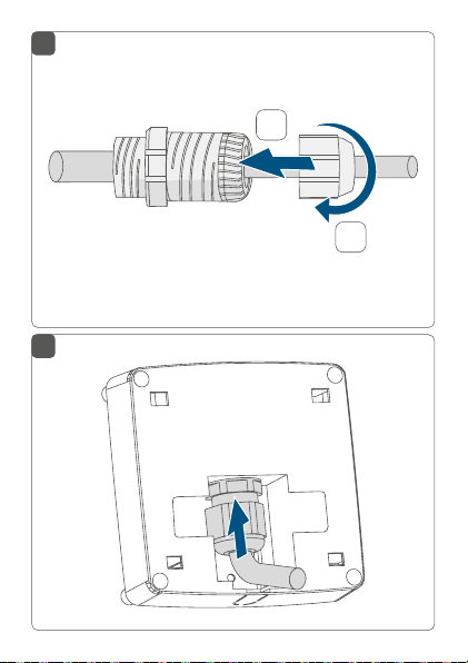
• Schrauben Sie die Mutter und die Gegenmutter
18
Aderendhülse [mm2]
Page 19

Inbetriebnahme
der mitgelieferten Kabelverschraubung (D) ab (s.
Abbildung 4).
• Führen Sie die Zuleitung durch die Mutter (s. Ab-
bildung 5).
• Führen Sie die Zuleitung so durch die Önung der
Kabelverschraubung, dass die Mutter anschließend wieder aufgedreht werden kann.
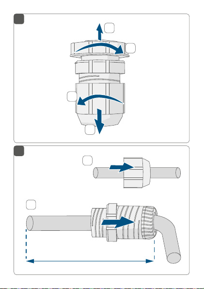
• Lassen Sie die ersten 15 cm der Leitung überstehen und drehen Sie die Mutter unterhalb von
15cm auf der Kabelverschraubung fest (s. Abbil-
dung 5+6).
• Führen Sie die Leitung mit der Kabelverschraubung durch die dafür vorgesehene Gehäuseönung (s. Abbildung 7).
• Führen Sie die Gegenmutter über das Ende der
Leitung und schrauben Sie sie auf der Kabelverschraubung fest (s. Abbildung 8).
Zum Festziehen oder auch zum Lösen der Mutter
können Sie optional einen Maulschlüssel verwenden (s. Abbildung 9).
• Schließen Sie die Leitung an die Anschlussklemmen am Gehäusedeckel an (s. Abbildung 8).
Zum Anschließen und auch zum Lösen der Leiter
ist der weiße Betätigungsdrücker oben auf den
Klemmen zu drücken.
19
Page 20

Inbetriebnahme
• Setzen Sie den Gehäusedeckel wieder auf und verschließen Sie das Gehäuse mittels der Schrauben.
• Versorgen Sie das Gerät über das Netzteil mit
Spannung.
5.3 Anlernen
Bitte lesen Sie diesen Abschnitt erst vollständig,
bevor Sie mit dem Anlernen beginnen.
Richten Sie zunächst Ihren Homematic IP Access
Point über die Homematic IP App ein, um weitere
Homematic IP Geräte im System nutzen zu können. Weitere Informationen dazu finden Sie in der
Bedienungsanleitung des Access Points.
Sie können das Gerät an den Access Point oder an
die Zentrale CCU2/CCU3 anlernen. Weitere Infor
mationen dazu entnehmen Sie bitte dem Homematic IP Anwenderhandbuch (zu finden im Downloadbereich unter www.homematic-ip.com).
Damit das Gerät in Ihr System integriert werden und mit
anderen Homematic IP Geräten kommunizieren kann,
muss es zunächst an den Homematic IP Access Point
angelernt werden.
Zum Anlernen gehen Sie wie folgt vor:
• Önen Sie die Homematic IP App auf Ihrem
Smartphone.
20
-
Page 21

Inbetriebnahme
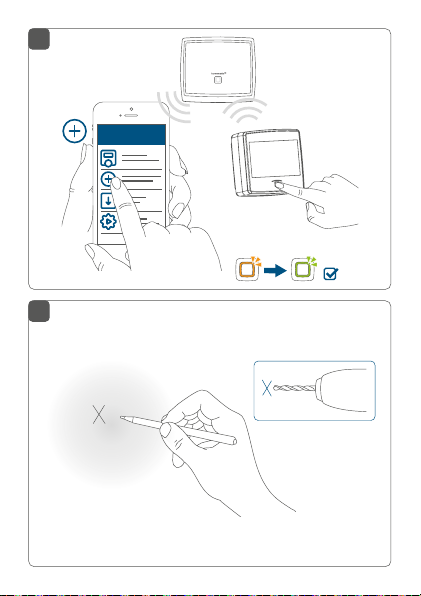
• Wählen Sie den Menüpunkt „Gerät anlernen“ aus
(s. Abbildung 10).
• Nach dem Herstellen der Spannungsversorgung
über ein geeignetes Netzteil, ist der Anlernmodus
ist für 3 Minuten aktiv.
Sie können den Anlernmodus manuell für weitere
3 Minuten starten, indem Sie die Systemtaste (B)
kurz drücken (s. Abbildung 10).
• Das Gerät erscheint automatisch in der Homematic IP App.
• Zur Bestätigung geben Sie in der App die letzten
vier Ziern der Gerätenummer (SGTIN) ein oder
scannen Sie den QR-Code. Die Gerätenummer
finden Sie auf dem Aufkleber im Lieferumfang
oder direkt am Gerät.
• Warten Sie, bis der Anlernvorgang abgeschlossen
ist.
• Zur Bestätigung eines erfolgreichen Anlernvorgangs leuchtet die LED (B) grün (s. Abbildung 10).
Das Gerät ist nun einsatzbereit.
• Leuchtet die LED rot, versuchen Sie es erneut.
• Vergeben Sie in der App einen Namen für das Gerät und ordnen Sie es einem Raum zu.
21
Page 22

Inbetriebnahme
5.4 Montagehinweise
Montieren Sie das Gerät so, dass es nicht herabfallen und Schäden herbeiführen kann.
Installieren Sie das Gerät nicht als höchsten Punkt
im freien Gelände (z. B. auf Gebäuden oder Masten). Es besteht Blitzschlaggefahr! Bei Montage
an Gebäuden sind die Vorschriften des Blitzschutzes einzuhalten.
Montieren Sie das Gerät so, das es keinen mechischen Belastungen und dem Einfluss von Vibrationen ausgesetzt ist.
Wählen Sie den Montageort so, dass das Gerät zu
Wartungszwecken erreichbar ist.
Achten Sie bei der Auswahl des Montageortes auf
den Verlauf elektrischer Leitungen bzw. auf vorhandene Versorgungsleitungen.
Betreiben Sie das Gerät nur im geschlossenen
Zustand.
Die Gehäuserückseite verfügt über zwei Ausbrechönungen zum Önen von Entwässerungslöchern. Bei Bedarf sind diese mit einem
spitzen Gegenstand vollständig zu önen. Der
22
Page 23

Inbetriebnahme
dabei entstehende Grat ist zu entfernen. Das Gerät sollte im 45-Grad-Winkel montiert werden,
damit die Feuchtigkeit durch die Ausbrechönungen ablaufen kann und das Gerät nicht durch
Eindringen von Feuchtigkeit beschädigt wird.
Der Montageort sollte so beschaen sein, dass
der Regensensor im 45-Grad-Winkel angebracht
werden kann. An geraden Flächen (wie z. B. der
Hauswand) kann dafür die 45-Grad-Halterung (F)
verwendet werden. Für Flächen, die schon im
richtigen Winkel sind, kann die 0-Grad-Halterung
(G) eingesetzt werden.
Montagehalterung 45 Grad
Verwendung bei geraden Flächen (wie z. B. an einer Hauswand) oder für die Montage an
einem Rohr.
Montagehalterung 0 Grad
Verwendung bei Flächen, die schon
im 45-Grad-Winkel sind.
23
Page 24

Inbetriebnahme
5.4.1 Montage an ebenen Flächen
Um das Gerät zu montieren, gehen Sie wie folgt vor:
• Wählen Sie einen geeigneten Montageort aus.
• Wählen Sie je nach Beschaenheit der Montagefläche eine der mitgelieferten Montagehalterungen (F oder G) aus.
• Halten Sie die Montagehalterung an die gewünschte Position.
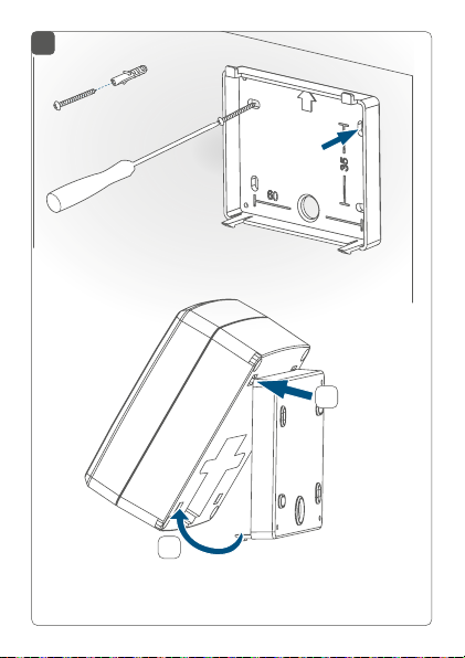
• Zeichnen Sie anhand der verwendeten Montagehalterung (die Lochabstände können Sie den Beschriftungen auf der Halterung entnehmen) zwei
Bohrlöcher mit einem Stift an der gewünschten
Position an (s. Abbildung 11). Je nach Beschaenheit des Untergrundes können Sie zwischen vier
Schraublöchern wählen.
• Bohren Sie die vorgezeichneten Löcher (s. Abbil-
dung 11).
Bei Steinwänden verwenden Sie einen 5 mm
Bohrer für die Dübel. Bei Holzwänden können Sie
die Löcher mit einem 1,5 mm Bohrer vorbohren,
um das Eindrehen der Schrauben zu erleichtern.
• Montieren Sie die Montagehalterung durch Eindrehen der mitgelieferten Dübel und Schrauben
(s. Abbildung 12 oder 13).
• Führen Sie die Leitung des Netzteils bei Bedarf
durch die Kabelönung der Montagehalterung.
24
Page 25

Inbetriebnahme
• Setzen Sie das Gerät zuerst auf die oberen, dann
auf die unteren Rastnasen der montierten Wandhalterung auf, bis es vollständig eingerastet ist (s.
Abbildung 12 oder 13).
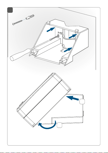
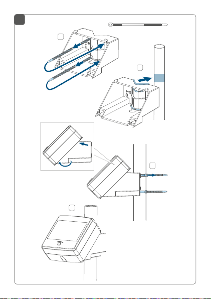
5.4.2 Montage an einem runden Gegenstand
Für die Befestigung des Regensensors an einem runden
Gegenstand (z. B. an einem Edelstahlmast), können Sie
die 45-Grad-Halterung (F) und die beiliegenden Kabelbinder verwenden.
• Führen Sie die Kabelbinder durch die dafür vorgesehenen Önungen in der 45-Grad-Halterung
(s. Abbildung 14).
• Halten Sie die Halterung an den Gegenstand, an
dem Sie sie befestigen wollen.
• Führen Sie die Kabelbinder von hinten durch die
parallel liegenden Önungen wieder nach vorne
und ziehen Sie sie um den Gegenstand zu (s. Ab-
bildung 14).
• Führen Sie die Leitung des Netzteils bei Bedarf
durch die Kabelönung der Montagehalterung.
• Setzen Sie das Gerät zuerst auf die oberen, dann
auf die unteren Rastnasen der montierten Wandhalterung auf, bis es vollständig eingerastet ist (s.
Abbildung 14).
25
Page 26

Fehlerbehebung
6 Fehlerbehebung
6.1 Befehl nicht bestätigt
Bestätigt mindestens ein Empfänger einen Befehl nicht,
leuchtet zum Abschluss der fehlerhaften Übertragung die
Geräte-LED (B) rot auf. Grund für die fehlerhafte Übertragung kann eine Funkstörung sein (s. „1 Hinweise zur
Anleitung“ auf Seite 14). Die fehlerhafte Übertragung
kann folgende Ursachen haben:
• Empfänger nicht erreichbar,
• Empfänger kann Befehl nicht ausführen (Lastausfall, mechanische Blockade etc.) oder
• Empfänger defekt.
6.2 Duty Cycle
Der Duty Cycle beschreibt eine gesetzlich geregelte Begrenzung der Sendezeit von Geräten im 868 MHz Bereich. Das Ziel dieser Regelung ist es, die Funktion aller im
868 MHz Bereich arbeitenden Geräte zu gewährleisten.
In dem von uns genutzten Frequenzbereich 868 MHz beträgt die maximale Sendezeit eines jeden Gerätes 1 % einer Stunde (also 36 Sekunden in einer Stunde). Die Geräte
dürfen bei Erreichen des 1 %-Limits nicht mehr senden,
bis diese zeitliche Begrenzung vorüber ist. Gemäß dieser
Richtlinie, werden Homematic IP Geräte zu 100 % normenkonform entwickelt und produziert.
Im normalen Betrieb wird der Duty Cycle in der Regel
nicht erreicht. Dies kann jedoch in Einzelfällen bei der Inbetriebnahme oder Erstinstallation eines Systems durch
26
Page 27

Fehlerbehebung
vermehrte und funkintensive Anlernprozesse der Fall sein.
Eine Überschreitung des Duty Cycle Limits wird durch ein
langes rotes Blinken der Geräte-LED (B) angezeigt und
kann sich durch temporär fehlende Funktion des Gerätes
äußern. Nach kurzer Zeit (max. 1 Stunde) ist die Funktion
des Gerätes wiederhergestellt.
6.3 Fehlercodes und Blinkfolgen
Blinkcode Bedeutung Lösung
Kurzes oranges
Blinken
1x langes
grünes
Leuchten
1x langes rotes
Leuchten
Funkübertragung/
Sendeversuch/
Datenübertragung
Vorgang
bestätigt
Vorgang
fehlgeschlagen oder Duty
Cycle-Limit
erreicht
Warten Sie, bis
die Übertragung
beendet ist.
Sie können mit
der Bedienung
fortfahren.
Versuchen Sie
es erneut (s. „6.1
Befehl nicht bestätigt“ auf Seite 26
oder „6.2 Duty
Cycle“ auf Seite
26).
27
Page 28

Fehlerbehebung
Kurzes oranges
Blinken
(alle 10 s)
Langes und
kurzes oranges
Blinken (im
Wechsel)
6x langes rotes
Blinken
1x oranges,
1x grünes
Leuchten (nach
Einlegen der
Batterien)
28
Anlernmodus
aktiv
Geben Sie die
letzten vier Ziern
der GeräteSeriennummer zur
Bestätigung ein (s.
„5.3 Anlernen“ auf
Seite 20).
Aktualisierung
der Gerätesoftware
Warten Sie, bis das
Update beendet
ist.
(OTAU)
Gerät defekt Achten Sie auf die
Anzeige in Ihrer
App oder wenden
Sie sich an Ihren
Fachhändler.
Testanzeige Nachdem die Test-
anzeige erloschen
ist, können Sie
fortfahren.
Page 29

Wiederherstellung der Werkseinstellungen
Kurzes grünes
Blinken
Initiale Regenerkennung
(bei aktivierter
Visualisierung)
Diese Funktion
ist standardmäßig
deaktiviert und
kann für Testzwecke bei der ersten
Inbetriebnahme
aktiviert werden.
7 Wiederherstellung der
Werkseinstellungen
Die Werkseinstellungen des Geräts können wiederhergestellt werden. Dabei gehen alle Einstellungen verloren.
Um die Werkseinstellungen des Geräts wiederherzustellen, gehen Sie wie folgt vor:
• Drücken Sie für 4 s auf die Systemtaste (B), bis
die LED (B) schnell orange zu blinken beginnt (s.
Abbildung 15).
• Lassen Sie die Systemtaste wieder los.
• Drücken Sie die Systemtaste erneut für 4 s, bis die
LED grün aufleuchtet (s. Abbildung 16).
• Lassen Sie die Systemtaste wieder los, um das
Wiederherstellen der Werkseinstellungen abzuschließen.
Das Gerät führt einen Neustart durch.
29
Page 30

Wartung und Reinigung
8 Wartung und Reinigung
Das Gerät ist wartungsfrei. Überlassen Sie eine
Reparatur einer Fachkraft.
Reinigen Sie das Gerät mit einem weichen, sauberen,
trockenen und fusselfreien Tuch. Verwenden Sie keine
lösemittelhaltigen Reinigungsmittel, das Kunststogehäuse und die Beschriftung können dadurch angegrien
werden.
9 Allgemeine Hinweise zum
Funkbetrieb
Die Funk-Übertragung wird auf einem nicht exklusiven
Übertragungsweg realisiert, weshalb Störungen nicht
ausgeschlossen werden können. Weitere Störeinflüsse
können durch Schaltvorgänge, Elektromotoren oder defekte Elektrogeräte hervorgerufen werden.
Die Reichweite in Gebäuden kann stark von der
im Freifeld abweichen. Außer der Sendeleistung
und den Empfangseigenschaften der Empfänger
spielen Umwelteinflüsse wie Luftfeuchtigkeit
neben baulichen Gegebenheiten vor Ort eine
wichtige Rolle.
30
Page 31

Technische Daten
Hiermit erklärt die eQ-3 AG, Maiburger Str. 29, 26789
Leer, Deutschland, dass der Funkanlagentyp Homematic IP HmIP-SRD der Richtlinie 2014/53/EU entspricht.
Der vollständige Text der EU-Konformitätserklärung
ist unter der folgenden Internetadresse verfügbar:
www.homematic-ip.com
10 Technische Daten
Geräte-Kurzbezeichnung: HmIP-SRD
Versorgungsspannung: 10-19 V
Stromaufnahme: max. 400 mA
Leistungsaufnahme im
Ruhebetrieb: 144 mW
Schutzart: IP44
Leitungsart und -querschnitt: starre und flexible Lei-
Leitungseinführungsönung: 4,5-10 mm
Umgebungstemperatur: -20 bis +55 °C
Abmessungen (B x H x T): 89 x 89 x 41 mm
Gewicht: 125 g
Funk-Frequenzband: 868,0-868,6 MHz
869,4-869,65 MHz
Max. Funk-Sendeleistung: 10 dBm
Empfängerkategorie: SRD Category 2
DC (max. 320 mA)
oder 12 V
AC/50 Hz (max.
400 mA)
tung ohne Aderendhülse,
0,2-1,5 mm²
31
Page 32

Technische Daten
Typ. Funk-Freifeldreichweite: 200 m
Duty Cycle: < 1 % pro h/< 10 % pro h
Technische Änderungen vorbehalten.
Entsorgungshinweis
Gerät nicht im Hausmüll entsorgen! Elektronische Geräte sind entsprechend der Richtlinie
über Elektro- und Elektronik-Altgeräte über die
örtlichen Sammelstellen für Elektronik-Altgeräte
zu entsorgen.
Konformitätshinweis
Das CE-Zeichen ist ein Freiverkehrszeichen, das
sich ausschließlich an die Behörden wendet und
keine Zusicherung von Eigenschaften beinhaltet.
Bei technischen Fragen zum Gerät wenden Sie
sich bitte an Ihren Fachhändler.
32
Page 33

Package contents
Quantity Description
1 Homematic IP Rain Sensor
2 Mounting brackets
2 Plugs 5 mm
2 Screws 3.0 x 30 mm
2 Cable tie
1 Torx key
1 Supplement sheet with safety instructions
1 User manual
Documentation © 2020 eQ-3 AG, Germany
All rights reserved. Translation from the original version in German. This manual may not be reproduced in any format, either in
whole or in part, nor may it be duplicated or edited by electronic,
mechanical or chemical means, without the written consent of
the publisher.
Typographical and printing errors cannot be excluded. However,
the information contained in this manual is reviewed on a regular
basis and any necessary corrections will be implemented in the
next edition. We accept no liability for technical or typographical
errors or the consequences thereof.
All trademarks and industrial property rights are acknowledged.
Printed in Hong Kong
Changes may be made without prior notice as a result of technical advances.
154918 (web)
Version 1.0 (04/2020)
33
Page 34

Table of contents
1 Information about this manual....................................35
2 Hazard information ........................................................35
3 Function and device overview ....................................37
4 General system information ........................................38
5 Start-up ............................................................................38
5.1 Selecting the power supply unit ...................................... 38
5.2 Establish power supply ...................................................... 39
5.3 Teaching-in ...........................................................................41
5.4 Notes on installation .......................................................... 42
5.4.1 Mounting on plane surfaces ................................ 44
5.4.2 Mounting on a round object ............................... 45
6 Troubleshooting ............................................................ 46
6.1 Command not confirmed ................................................. 46
6.2 Duty cycle ............................................................................47
6.3 Error codes and flashing sequences .............................. 48
7 Restore factory settings ............................................... 49
8 Maintenance and cleaning .......................................... 50
9 General information about radio operation ............ 50
10 Technical specifications ................................................ 51
34
Page 35

Information about this manual
1 Information about this manual
Read this manual carefully before beginning operation
with your Homematic IP components. Keep the manual
so you can refer to it at a later date if you need to. If you
hand over the device to other persons for use, hand over
this manual as well.
Symbols used:
Attention!
This indicates a hazard.
Please note:
This section contains important additional
information.
2 Hazard information
The device does not contain any parts that can be
maintained by the user. In the event of an error,
have the device checked by an expert.
We do not assume any liability for damage to
property or personal injury caused by improper
use or the failure to observe the hazard
information. In such cases, any claim under
warranty is extinguished! For consequential
damages, we assume no liability!
35
Page 36

Hazard information
For safety and licensing reasons (CE),
unauthorized change and/or modification of the
device is not permitted.
The device is not a toy; do not allow children to
play with it. Do not leave packaging material lying
around. Plastic films/bags, pieces of polystyrene,
etc. can be dangerous in the hands of a child.
Do not use the device if there are signs of damage
to the housing or operating elements, for
example, or if it demonstrates a malfunction. If
you have any doubts, have the device checked by
an expert.
The device is only intended for use within
residential, business and commercial areas as
well as in small enterprises.
Using the device for any purpose other than that
described in this operating manual does not fall
within the scope of intended use and shall
invalidate any warranty or liability.
36
Page 37

Function and device overview
3 Function and device overview
The Homematic IP Rain Sensor detects even the smallest
amounts of rain or snow via the integrated sensor area.
As soon as rainfall begins, the sensor transmits the
information to connected Homematic IP devices as well
as the Homematic IP smartphone app. Thus, for example
the awning can be retracted automatically in connection
with a Homematic IP Shutter Actuator. The warning via the
app and push-notification on the smartphone can be used
to react early in the event of rain to prevent any damage
caused by open roof windows, for example.
The integrated sensor heating ensures that the sensor
area dries immediately. This avoids functional limitations
caused by dew and ice formation. Thanks to the wide
temperature range and waterproof housing (IP44), it can
be used even under extreme conditions of -20 to +55 °C.
Device overview (see figure 1+2):
(A) Sensor area
(B) System button (teach-in button and LED)
(C) Mounting bracket latch
(D) Cable glands for connecting cable
(E) Housing cover gland
(F) Accessory components: Mounting bracket 45
degrees
(G) Accessory components: Mounting bracket 0 degrees
(H) Cable bushing (optional)
37
Page 38

General system information
4 General system information
This device is part of the Homematic IP smart home
system and works with the Homematic IP radio protocol.
All devices of the system can be configured comfortably
and individually with the Homematic IP smartphone
app. Alternatively, you can operate the Homematic IP
devices via the Central Control Unit CCU2/CCU3 or in
connection with various partner solutions. The available
functions provided by the system in combination with
other components are described in the Homematic IP
User Guide. All current technical documents and updates
are provided at www.homematic-ip.com.
5 Start-up
5.1 Selecting the power supply unit
The rain sensor is operated via a separate power supply
unit (not included in the scope of supply).
The basic requirements to the power supply unit are:
• Safety extra-low voltage (SELV)
• Voltage: 10-19 V
AC/50 Hz (400 mA min.)
12V
• Cable length 30 m max. (at least 0.2 mm)
38
DC (320 mA min.) or
Page 39

Start-up
5.2 Establish power supply
In order to ensure that the equipment is
electrically safe, the feeding source must be a
safety extra-low voltage.
Please note the insulation stripping length of the
conductor to be connected, indicated on the
device.
Permitted cable cross sections for connecting to the rain
sensor are:
rigid cable [mm2]
0.2.-1.5 0.2.-1.5
To integrate the rain sensor into your Homematic IP
system, power has to be supplied via an appropriate
power supply unit. Therefore, proceed as follows:
• Loosen the four screws (E) on the back of the
housing using the Torx key supplied (see figure 3).
• Remove the housing cover.
• If necessary, remove the perforated cable
bushing to facilitate installation. Then, lead the
power supply cable through it.
• Unscrew the nut and the locknut of the supplied
cable gland (D) (see figure 4).
• Lead the supply cable through the nut (see figure
5).
flexible cable without ferrule [mm2]
39
Page 40

Start-up
• Lead the supply cable through the opening of the
cable gland so that the nut can be screwed on
again afterwards.
• Extend the first 15 cm of the cable and tighten the
nut below 15cm on the cable gland (see figure
5+6).
• Lead the cable with the cable gland through the
housing opening provided for it (see figure 7).
• Lead the locknut over the end of the cable and
screw it onto the cable gland (see figure 8).
To tighten or loosen the nut, you can optionally
use an open-end wrench (see figure 9).
• Connect the cable to the connecting terminals
on the housing cover (see figure 8).
To connect or loosen the conductor, the white
actuation lever at the top of the clamp has to be
pressed.
• Place the housing cover back on and close the
device using the screws.
• Provide power supply for the device using the
power supply unit.
40
Page 41

Start-up
5.3 Teaching-in
Read this entire section before starting the teachin procedure.
First set up your Homematic IP Access Point via
the Homematic IP app to enable operation of
other Homematic IP devices within your system.
For further information, refer to the operating
manual of the Access Point.
You can connect the device either to the Access
Point or to the Homematic Central Control Unit
CCU2/CCU3. For detailed information, refer to the
Homematic IP User Guide, available for download
in the download area of www.homematic-ip.com.
To integrate the device into your system and enable it to
communicate with other Homematic IP devices, it has to
be connected to your Homematic IP Access Point first.
To connect it, proceed as follows:
• Open the Homematic IP app on your smartphone.
• Select the menu item “Teach-in device” (see
figure 10).
• After establishing supply voltage via an
appropriate power supply unit the teach-in mode
remains activated for 3 minutes.
41
Page 42

Start-up
You can manually start the teach-in mode for
another 3 minutes by pressing the system button
(B) shortly (see figure 10).
• Your device will automatically appear in the
Homematic IP app.
• To confirm, enter the last four digits of the device
number (SGTIN) in your app or scan the QR code.
Therefore, see the sticker supplied or attached to
the device.
• Wait until the connection is completed.
• If connection of the device was successful, the
LED (B) lights up green (see figure 10). The device
is now ready for use.
• If the LED lights up red, please try again.
• In the app, give the device a name and allocate
it to a room.
5.4 Notes on installation
The device must be mounted in such a way that it
cannot fall down or cause damage.
Do not install the device so that it is the highest
point in an outdoor area (e.g. on buildings or
masts). This creates a risk of lightning strikes.
When installing the device on buildings, lightning
protection regulations must be observed.
42
Page 43

Start-up
The device must be mounted so that it is
protected from mechanical loads and the eects
of vibrations.
Select an installation site at which you can access
the device for maintenance.
When selecting the installation location, check
for electrical wires and power supply cables.
Do operate the device only when its closed.
There are two break-out openings at the back
side of the device for opening drainage holes. If
required, they can be fully opened using a pointed
object. Any burr resulting from that has to be
removed. The device should be mounted in a 45
degree angle so that moisture can drain through
the break-out openings and the unit is not
damaged by incoming moisture.
The mounting location should be constructed in
that way that the rain sensor can be installed in a
45 degree angle. For even surfaces (such as a
house wall) the 45 degree bracket (F) can be
used. For surfaces that are already at the correct
angle, the 0 degree bracket (G) can be used.
43
Page 44

Start-up
Mounting bracket 45 degrees
Used for plane surfaces (such
as on a house wall) or for
mounting on a pipe.
Mounting bracket 0 degrees
Used for surfaces that are already at
a 45 degree angle.
5.4.1 Mounting on plane surfaces
To install the device, proceed as follows:
• Choose a site for installation.
• Select one of the supplied mounting brackets
depending on the condition of the mounting
surface (F or G).
• Position the mounting bracket to the desired
location.
• Mark two bore holes with the mounting bracket
used with a pen at the desired position (the
hole spacing can be seen from the labels on
44
Page 45

Start-up
the bracket) (see figure 11). Depending on the
condition of the surface you can choose between
four screw holes.
• Drill the marked holes (see fig. 11).
If you are working with a stone wall, drill the
marked two 5 mm holes and insert the plugs
supplied. If you are using a wooden wall, you can
pre-drill 1.5 mm holes to make screws easier to
insert.
• Use the supplied screws and plugs to fasten the
mounting bracket (see figure 12 or 13).
• If necessary, lead the cable of the power supply
unit through the cable opening of the mounting
bracket.
• Place the device first on the upper and then on
the lower lugs of the mounted wall bracket until
it is fully engaged (see figure 12 or 13).
5.4.2 Mounting on a round object
To attach the rain sensor to a round object (e.g. a stainless
steel pipe), you can use the 45 degree bracket (F) and the
included cable ties.
• Lead the cable ties trough the openings provided
in the 45 degree bracket (see figure 14).
• Hold the bracket to the object to which you want
to attach it.
45
Page 46

Troubleshooting
• Lead the cable ties from behind through the
parallel openings and pull them forward again
around the object (see figure 14).
• If necessary, lead the cable of the power supply
unit through the cable opening of the mounting
bracket.
• Place the device first on the upper and then on
the lower lugs of the mounted wall bracket until
it is fully engaged (see figure 14).
6 Troubleshooting
6.1 Command not confirmed
If at least one receiver does not confirm a command,
the device LED (B) lights up red at the end of the failed
transmission process. The failed transmission may be
caused by radio interference (see “1 Information about
this manual” on page 35). The failed transmission may
also be caused by the following:
• Receiver cannot be reached.
• Receiver is unable to execute the command (load
failure, mechanical blockade, etc.).
• Receiver is defective.
46
Page 47

Troubleshooting
6.2 Duty cycle
The duty cycle is a legally regulated limit of the
transmission time of devices in the 868 MHz range. The
aim of this regulation is to safeguard the operation of all
devices working in the 868 MHz range.
In the 868 MHz frequency range we use, the maximum
transmission time of any device is 1% of an hour (i.e. 36
seconds in an hour). Devices must cease transmission
when they reach the 1% limit until this time restriction
comes to an end. Homematic IP devices are designed
and produced with 100% conformity to this regulation.
During normal operation, the duty cycle is not usually
reached. However, repeated and radio-intensive teachin processes mean that it may be reached in isolated
instances during start-up or initial installation of a system.
If the duty cycle is exceeded, this is indicated by one long
red flashing of the device LED (B), and may manifest itself
in the device temporarily working incorrectly. The device
starts working correctly again after a short period (max.
1 hour).
47
Page 48

Troubleshooting
6.3 Error codes and flashing sequences
Flashing code Meaning Solution
Short orange
flashing
1x long green
lighting
1x long red
lighting
Short orange
flashing
(every 10 s)
Long and short
orange flashing
(alternating)
48
Radio transmission/send
attempt/data
transmission
Transmission
confirmed
Transmission
failed or duty
cycle limit is
reached
Teach-in mode
active
Update of device software
(OTAU)
Wait until the
transmission is
completed.
You can continue
operation.
Please try again
(see sec. “6.1
Command not
confirmed” on
page 46 or “6.2
Duty cycle” on
page 47).
Enter the last four
numbers of the
device serial number to confirm (see
“5.3 Teaching-in”
on page 41).
Wait until the update is completed.
Page 49

Restore factory settings
6x long red
flashing
1x orange, 1x
green lighting
(after inserting
batteries)
Short green
flashing
Device
defective
Test display Once the test dis-
Initial rain
detection
(with activated
visualisation)
Have a look at your
app for error message or contact
your retailer.
play has stopped,
you can continue.
This function is
deactivated by
default and can be
activated for test
purposes during
initial set-up.
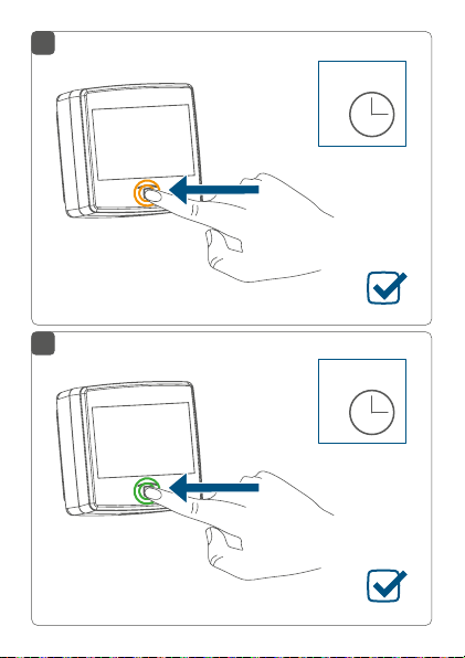
7 Restore factory settings
The factory settings of the device can be restored.
If you do this, you will lose all your settings.
To restore the factory settings of the device, proceed as
follows:
• Press and hold down the system button (B) until
the LED (B) quickly starts flashing orange (see
figure 15).
• Release the system button again.
49
Page 50

Maintenance and cleaning
• Press and hold down the system button again
for 4 seconds, until the LED lights up green (see
figure 16).
• Release the system button to finish the procedure.
The device will perform a restart.
8 Maintenance and cleaning
The product does not require any maintenance.
Enlist the help of an expert to carry out any
repairs.
Clean the device using a soft, lint-free cloth that is clean
and dry. Do not use any detergents containing solvents,
as they could corrode the plastic housing and label.
9 General information about radio
operation
Radio transmission is performed on a non-exclusive
transmission path, which means that there is a possibility
of interference occurring.
Interference can also be caused by switching operations,
electrical motors or defective electrical devices.
50
Page 51

Technical specifications
The range of transmission within buildings can
dier greatly from that available in the open air.
Besides the transmitting power and the reception
characteristics of the receiver, environmental
factors such as humidity in the vicinity have an
important role to play, as do on-site structural/
screening conditions.
Hereby, eQ-3 AG, Maiburger Str. 29, 26789 Leer/Germany
declares that the radio equipment type Homematic IP
Rain Sensor (HmIP-SRD) is in compliance with Directive
2014/53/EU. The full text of the EU declaration of
conformity is available at the following internet address:
www.homematic-ip.com
10 Technical specifications
Device short name: HmIP-SRD
Supply voltage: 10-19 V
Current consumption: 400 mA max.
Standby power consumption:
144 mW
Degree of protection: IP44
Cable type and cross section: rigid and flexible cable
DC (320 mA max.)
AC/50 Hz (400 mA
or 12 V
max.)
without ferrule,
0.2-1.5 mm²
51
Page 52

Technical specifications
Cable entry opening: 4.5-10 mm
Ambient temperature: -20 to +55 °C
Dimensions (W x H x D): 89 x 89 x 41 mm
Weight: 125 g
Radio frequency band: 868.0-868.6 MHz
869.4-869.65 MHz
Maximum radiated power: 10 dBm
Receiver category: SRD category 2
Typical open area RF range: 200 m
Duty cycle: < 1 % per h/< 10 % per h
Subject to technical changes.
Instructions for disposal
Do not dispose of the device with regular
domestic waste! Electronic equipment must be
disposed of at local collection points for waste
electronic equipment in compliance with the
Waste Electrical and Electronic Equipment
Directive.
Information about conformity
The CE sign is a free trading sign addressed
exclusively to the authorities and does not
include any warranty of any properties.
For technical support, contact your specialist
dealer.
52
Page 53

Kostenloser Download der Homematic IP App!
Free download of the Homematic IP app!
Bevollmächtigter des Herstellers:
Manufacturer’s authorised representative:
eQ-3 AG
Maiburger Straße 29
26789 Leer / GERMANY
www.eQ-3.de
 Loading...