

Page 1
Installations- und
Bedienungsanleitung
Installation and
operating manual
Dimmaktor für Hutschienenmontage – 3-fach
Dimming Actuator for DIN rail
mount – 3 channels
HmIP-DRDI3
S. 2
p. 39
Page 2

Lieferumfang
Anzahl Bezeichnung
1 Homematic IP Dimmaktor für
1 Bedienungsanleitung
Dokumentation © 2019 eQ-3 AG, Deutschland
Alle Rechte vorbehalten. Ohne schriftliche Zustimmung des
Herausgebers darf diese Anleitung auch nicht auszugsweise in
irgendeiner Form reproduziert werden oder unter Verwendung
elektronischer, mechanischer oder chemischer Verfahren vervielfältigt oder verarbeitet werden.
Es ist möglich, dass die vorliegende Anleitung noch drucktechnische Mängel oder Druckfehler aufweist. Die Angaben in dieser
Anleitung werden jedoch regelmäßig überprüft und Korrekturen
in der nächsten Ausgabe vorgenommen. Für Fehler technischer
oder drucktechnischer Art und ihre Folgen übernehmen wir keine
Haftung.
Alle Warenzeichen und Schutzrechte werden anerkannt.
Printed in Hong Kong
Änderungen im Sinne des technischen Fortschritts können ohne
Vorankündigung vorgenommen werden.
154436 (web)
Version 1.1 (05/2020)
Hutschienenmontage – 3-fach
Page 3
1
A
B
C
D
F
I
J
E
I
H
G
Page 4

2
OFF
3
1
2
Page 5
4
5
Page 6
6
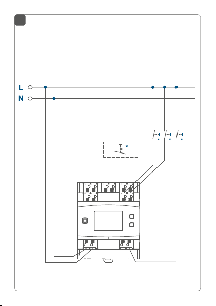
Anschluss von verschiedenen Lasten (Ausgänge) und
Versorgungsspannung Kanal 1 und 2
Connection of dierent loads (outputs) and supply
voltage channel 1 and 2
Page 7
7
Anschluss von Tastern/Schaltern (Eingänge) und
Geräte-Versorgungsspannung
Connection of push-buttons/switches (inputs) and
device supply voltage
Page 8
8
ON
9
HAP
Homematic IP
Page 9
101112
Page 10
13
4 s
Page 11
14
4 s
Page 12

Inhaltsverzeichnis
1 Hinweise zur Anleitung ................................................. 13
2 Gefahrenhinweise .......................................................... 13
3 Funktion und Geräteübersicht ....................................19
4 Allgemeine Systeminformationen ..............................21
5 Inbetriebnahme ..............................................................22
5.1 Installationshinweise .......................................................... 22
5.2 Montage und Installation .................................................. 24
5.3 Anlernen ................................................................................27
6 Bedienung ........................................................................29
7 Fehlerbehebung ............................................................. 31
7.1 Fehlercodes und Blinkfolgen ............................................31
7.2 Befehl nicht bestätigt ......................................................... 32
7.3 Duty Cycle ........................................................................... 33
8 Wiederherstellung der Werkseinstellungen ..............34
9 Wartung und Reinigung ................................................34
10 Allgemeine Hinweise zum Funkbetrieb .....................35
11 Technische Daten ..........................................................36
12
Page 13
Hinweise zur Anleitung
1 Hinweise zur Anleitung
Lesen Sie diese Anleitung sorgfältig, bevor Sie Ihr Homematic IP Gerät in Betrieb nehmen. Bewahren Sie die Anleitung zum späteren Nachschlagen auf!
Wenn Sie das Gerät anderen Personen zur Nutzung überlassen, übergeben Sie auch diese Anleitung.
Benutzte Symbole:
Achtung!
Hier wird auf eine Gefahr hingewiesen.
Hinweis. Dieser Abschnitt enthält zusätzliche
wichtige Informationen.
2 Gefahrenhinweise
Önen Sie das Gerät nicht. Es enthält keine durch
den Anwender zu wartenden Teile. Das Önen
birgt die Gefahr eines Stromschlages. Lassen Sie
das Gerät im Fehlerfall von einer Fachkraft prüfen.
Aus Sicherheits- und Zulassungsgründen (CE) ist
das eigenmächtige Umbauen und/oder Verändern des Geräts nicht gestattet.
13
Page 14
Gefahrenhinweise
Verwenden Sie das Gerät nicht, wenn es von außen erkennbare Schäden, z. B. am Gehäuse, an
Bedienelementen oder an den Anschlussbuchsen
ausweist. Lassen Sie das Gerät im Zweifelsfall von
einer Fachkraft prüfen.
Betreiben Sie das Gerät nur in trockener sowie
staubfreier Umgebung, setzen Sie es keinem Einfluss von Feuchtigkeit, Vibrationen, ständiger
Sonnen- oder anderer Wärmeeinstrahlung, übermäßiger Kälte und keinen mechanischen Belastungen aus.
Das Gerät ist kein Spielzeug! Erlauben Sie Kindern
nicht damit zu spielen. Lassen Sie das Verpackungsmaterial nicht achtlos liegen. Plastikfolien/
-tüten, Styroporteile etc. können für Kinder zu
einem gefährlichen Spielzeug werden.
Bei Sach- oder Personenschäden, die durch unsachgemäße Handhabung oder Nichtbeachten
der Gefahrenhinweise verursacht werden, übernehmen wir keine Haftung. In solchen Fällen erlischt jeder Gewährleistungsanspruch! Für Folgeschäden übernehmen wir keine Haftung!
14
Page 15
Gefahrenhinweise
Der Aktor ist Teil der Gebäudeinstallation. Bei der
Planung und Errichtung sind die einschlägigen
Normen und Richtlinien des Landes zu beachten.
Der Betrieb des Geräts ist ausschließlich am
230 V/50 Hz-Wechselspannungsnetz zulässig.
Arbeiten am 230-V-Netz dürfen nur von einer
Elektrofachkraft (nach VDE 0100) erfolgen. Dabei
sind die geltenden Unfallverhütungsvorschriften
zu beachten. Zur Vermeidung eines elektrischen
Schlages am Gerät, schalten Sie bitte die Netzspannung frei (Sicherungsautomat abschalten).
Bei Nichtbeachtung der Installationshinweise
können Brand oder andere Gefahren entstehen.
An die Anschlussklemmen der Ein- und Ausgänge,
inkl. der Nebenstelleneingänge, dürfen keine
SELV-/PELV-Stromkreise angeschlossen werden.
Beachten Sie beim Anschluss an die
Geräteklemmen die hierfür zulässigen Leitungen
und Leitungsquerschnitte.
Die angeschlossenen Verbraucher müssen über
eine ausreichende Isolierung verfügen.
Eine Überlastung kann zur Zerstörung des Geräts,
zu einem Brand oder zu einem elektrischen
Schlag führen.
15
Page 16
Gefahrenhinweise
Beachten Sie vor Anschluss eines Verbrauchers
technischen Daten, insbesondere die maximal
zulässige Schaltleistung der Lastkreise und Art des
anzuschließenden Verbrauchers. Belasten Sie den
Aktor nur bis zur angegebenen Leistungsgrenze.
Für den sicheren Betrieb muss das Gerät in einen
Stromkreisverteiler entsprechend VDE 0603, DIN
43871 (Niederspannungsunterverteilung (NSUV)),
DIN 18015-x eingebaut werden. Die Montage muss
auf einer Tragschiene (Hutschiene, DIN-Rail) lt.
60715 erfolgen. Installation und Verdrahtung
EN
sind entsprechend VDE 0100 (VDE 0100-410, VDE
0100-510 usw.) durchzuführen. Es sind die Vor
schriften der Technischen Anschlussbestimmungen
(TAB) des Energieversorgers zu berücksichtigen.
Vor Einbau und Anschluss des Geräts freischalten
und spannungsführende Teile in der Umgebung
abdecken.
Gefahr durch elektrischen Schlag. Gerät ist nicht
zum Freischalten geeignet. Auch bei ausgeschaltetem Ausgang ist die Last nicht galvanisch vom
Netz getrennt.
Keine Leuchten mit integriertem Dimmer anschließen. Gerät kann beschädigt werden.
16
die
-
Page 17
Gefahrenhinweise
Gefahr durch elektrischen Schlag. Vor Arbeiten
am Gerät oder vor Auswechseln von Leuchtmitteln Netzspannung freischalten und Sicherungsautomaten abschalten.
Der Dimmaktor ist ausschließlich für Glühlampen
sowie für Hochvolt-Halogenlampen und Nieder
volt- Halogenlampen mit elektronischen Transformatorensowie dimmbare LED-Lampen geeignet!
Keine LED- oder Kompaktleuchtstoampen anschließen, die nicht ausdrücklich zum Dimmen
geeignet sind. Gerät kann beschädigt werden.
Setzen Sie beim Betrieb mit elektronischen Vorschaltgeräten nur Transformatoren ein, die den
Anforderungen nach DIN EN 61347-1 sowie DIN
EN 61047 entsprechen.
Schließen Sie am Dimmaktor nur ohmsche und
kapazitive Lampenlasten und keine Fernseher,
R,C
Computer, Motoren etc. an.
Das Gerät kann zur Vermeidung von Helligkeitsschwankungen Rundsteuersignale erkennen.
Trotzdem kann kurzzeitiges Flackern des Leuchtmittels auf Grund von Rundsteuersignalen nicht
vollständig ausgeschlossen werden.
-
17
Page 18
Gefahrenhinweise
Geräte mit elektronischen Netzteilen (z. B. Hochvolt-LED-Leuchtmittel) stellen keine ohmschen
Lasten dar. Sie können Einschaltströme von über
100 A erzeugen. Schalten solcher Verbraucher führt
zu vorzeitigem Verschleiß des Aktors. Wir empfeh
len in solchen Fällen die Verwendung von Einschaltstrombegrenzern an den Schaltausgängen.
Das Gerät ist nur für den Einsatz in Wohnbereichen, Geschäfts- und Gewerbebereichen sowie
in Kleinbetrieben bestimmt.
-
Bei Einsatz in einer Sicherheitsanwendung ist das
Gerät/System in Verbindung mit einer USV (unter
brechungsfreie Stromversorgung) zu betreiben,
um einen möglichen Netzausfall zu überbrücken.
Jeder andere Einsatz, als der in dieser Bedienungsanleitung beschriebene, ist nicht bestimmungsgemäß und führt zu Gewährleistungs- und
Haftungsausschluss.
18
-
Page 19

Funktion und Geräteübersicht
3 Funktion und Geräteübersicht
Der Homematic IP Dimmaktor – 3-fach lässt sich einfach auf einer Hutschiene in einem Stromkreisverteiler
montieren. Einmal installiert, schaltet und dimmt er angeschlossene Leuchten über drei unabhängige Kanäle.
Im Homematic IP System kann der Dimmaktor die angeschlossenen Leuchten komfortabel über angelernte
Funk-Taster, Funk-Fernbedienungen oder über die kostenlose Homematic IP Smartphone-App schalten und
dimmen. Über angeschlossene konventionelle Taster
oder Schalter ist zudem eine direkte Bedienung möglich.
Der Dimmaktor ermöglicht das Dimmen von
• normalen Glühlampen,
• Hochvolt-Halogenlampen,
• Niedervolt-Halogenlampen mit elektronischem
Trafo,
• dimmbaren Energiesparlampen
• dimmbaren LED-Lampen
*1
Der nutzbare Dimmbereich ist meist stark eingeschränkt.
*2
Ein korrektes Dimmverhalten mit beliebigen LED-Lampen ist
nicht garantiert.
*1
und
*2
.
19
Page 20
Funktion und Geräteübersicht
1 1
1
1
1
RX
1 1
RX
TX
1 1
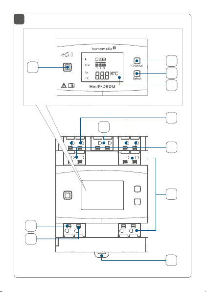
Geräteübersicht (s. Abbildung 1):
(A) Systemtaste (Anlerntaste und LED)
(B) Channel-Taste
(C) Select-Taste
(D) LC-Display
(E) Anschlussklemmen für Taster/Schalter Kanal 1-3
(F) Anschluss
(G) Verrastung für die Hutschienenmontage
Anschlussklemme Außenleiter (Geräteversor-
(H)
gung/Kanal 3)
(I) Anschlussklemme Neutralleiter
(J) Anschlussklemmen für den Verbraucher (Last)
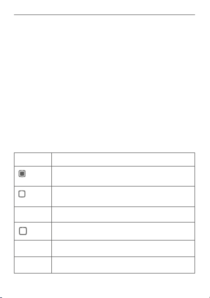
Displayübersicht (s. Abbildung 1):
Symbol Bedeutung
klemmen für Außenleiter (Kanal 1 und 2)
Kanal eingeschaltet
Kanal ausgeschaltet
Eingang nicht betätigt
Eingang betätigt
Daten werden empfangen
Daten werden gesendet
20
Page 21

Allgemeine Systeminformationen
Prozentangabe (eingeschaltet, wenn
der Schaltzustand oder der Duty-Cycle
angezeigt wird)
Temperaturangabe (eingeschaltet, wenn
Temperatur angezeigt wird)
4 Allgemeine Systeminformationen
Dieses Gerät ist Teil des Homematic IP Smart-HomeSystems und kommuniziert über das Homematic IP
Funkprotokoll. Alle Geräte des Systems können komfortabel und individuell per Smartphone über die Homematic IP App konfiguriert werden. Alternativ haben Sie
die Möglichkeit, Homematic IP Geräte über die Zentrale CCU2/CCU3 oder in Verbindung mit vielen Partnerlösungen zu betreiben. Welcher Funktionsumfang
sich innerhalb des Systems im Zusammenspiel mit weiteren Komponenten ergibt, entnehmen Sie bitte dem
Homematic IP Anwenderhandbuch. Alle technischen
Dokumente und Updates finden Sie stets aktuell unter
www.homematic-ip.com.
21
Page 22

Inbetriebnahme
5 Inbetriebnahme
5.1 Installationshinweise
Bitte notieren Sie sich vor der Installation die auf
dem Gerät angebrachte Gerätenummer (SGTIN)
und den Verwendungszweck, damit Sie das Gerät
im Nachhinein leichter zuordnen können. Alternativ steht die Gerätenummer auch auf dem beiliegenden QR-Code-Aufkleber.
Hinweis! Installation nur durch Personen mit
einschlägigen elektrotechnischen Kenntnissen
und Erfahrungen!*
Durch eine unsachgemäße Installation gefährden Sie
• Ihr eigenes Leben;
• das Leben der Nutzer der elektrischen Anlage.
Mit einer unsachgemäßen Installation riskieren Sie
schwere Sachschäden, z. B. durch Brand. Es droht für Sie
die persönliche Haftung bei Personen- und Sachschäden.
Wenden Sie sich an einen Elektroinstallateur!
Erforderliche Fachkenntnisse für die Installation:
*
Für die Installation sind insbesondere folgende Fachkenntnisse erforderlich:
• Die anzuwendenden „5 Sicherheitsregeln“:
Freischalten; gegen Wiedereinschalten sichern;
Spannungsfreiheit feststellen; Erden und Kurzschließen;
benachbarte, unter Spannung stehende Teile abdecken
22
Page 23

Inbetriebnahme
oder abschranken;
• Auswahl des geeigneten Werkzeuges, der Messgeräte
und ggf. der persönlichen Schutzausrüstung;
• Auswertung der Messergebnisse;
• Auswahl des Elektroinstallationsmaterials zur Sicherstellung der Abschaltbedingungen;
• IP-Schutzarten;
• Einbau des Elektroinstallationsmaterials;
• Art des Versorgungsnetzes (TN-System, IT-System,
TT-System) und die daraus folgenden Anschlussbedingungen (klassische Nullung, Schutzerdung, erforderliche
Zusatzmaßnahmen etc.).
Beachten Sie bei der Installation die Gefahrenhinweise gemäß „2 Gefahrenhinweise“ auf Seite 13.
Beachten Sie die auf dem Gerät angegebene Abisolierlänge der anzuschließenden Leiter.
Zugelassene Leitungsquerschnitte zum Anschluss an den
Schaltaktor sind:
Starre Leitung [mm2] Flexible Leitung ohne
Aderendhülse [mm2]
0,75-2,5 0,75-2,5
23
Page 24

Inbetriebnahme
5.2 Montage und Installation
Bitte lesen Sie diesen Abschnitt erst vollständig,
bevor Sie mit der Installation beginnen.
Die Laststromkreise müssen mit einem Leitungsschutzschalter gemäß EN60898-1 (Auslösecharakteristik B oder C, max. 16 A Nennstrom, min.
6 kA Abschaltvermögen, Energiebegrenzungsklasse 3) abgesichert sein.
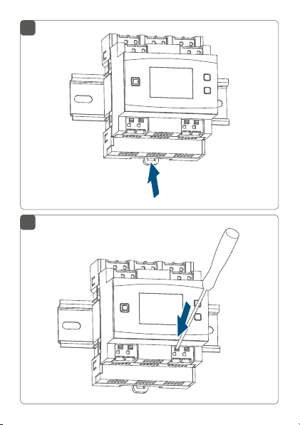
Für die Installation des Dimmaktors auf einer Hutschiene
im Stromkreisverteiler gehen Sie wie folgt vor:
• Schalten Sie den Stromkreisverteiler frei (s. Ab-
bildung 2) und decken ggf. spannungsführende
Teile ab (s. Sicherheitsregeln).
• Entfernen Sie die Abdeckung des Stromkreisverteilers.
• Setzen Sie den Dimmaktor auf die Hutschiene
auf (s. Abbildung 3). Achten Sie darauf, dass die
Schrift auf dem Gerät und im Display für Sie lesbar ist und die Anschlussklemmen der Ka näle 1
und 3 oben liegen.
• Achten Sie darauf, dass die Rastfeder (G) komplett
einrastet und das Gerät fest auf der Schiene sitzt
(s. Abbildung 4).
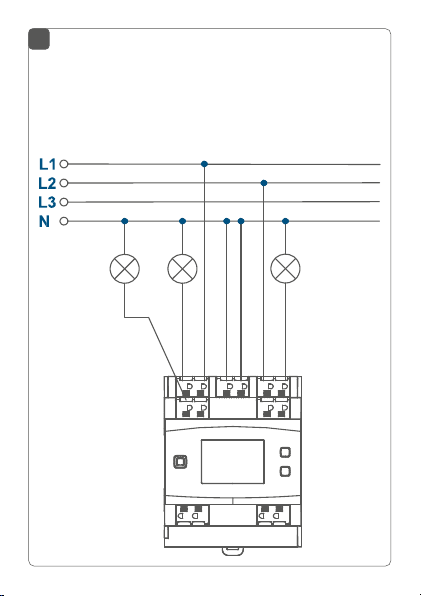
• Verdrahten Sie das Gerät gemäß den Anschlusszeichnungen in Abbildung 6 oder 7.
• Schließen Sie den Außenleiter an die Klemme (F
24
Page 25

Inbetriebnahme
und H), die gedimmte Phase (zum Verbraucher)
an die Klemmen (J) sowie den Neutralleiter an
die entsprechenden Klemmen (I) an (s. Abbildung
6+7). Es können beliebige Außenleiter (L1, L2, L3)
angeschlossen werden.
Die Eigenversorgung des Dimmaktors sowie die
Versorgung des dritten Kanals erfolgt über die
Klemmen L/3L und N/3N.
Die Anschlüsse des Neutralleiters (I) sind geräteintern nicht miteinander verbunden. Daher müssen
alle drei Klemmen (1N, 2N, N/3N) an den Neutrallei
ter angeschlossen werden. Falls die drei Lampenstromkreise über separate Fehlerstrom-Schutzschalter abgesichert werden, müssen auch jeweils
getrennte Neutralleiter angeschlossen werden.
Der Anschluss für den Außenleiter ist mit einem
Pfeil in Richtung Gerätemitte und die geschaltete
Phase mit einem Pfeil nach außen gekennzeichnet. Zum Anschließen und auch zum Lösen der
Leiter ist der weiße Betätigungsdrücker oben auf
den Klemmen zu drücken (s. Abbildung 5).
Die Netzklemmen dürfen nur zum Anschluss der
Netzspannung an das Gerät bzw. zum Anschluss
von Verbrauchern an das Gerät verwendet werden.
25
Page 26

Inbetriebnahme
Das Weiterverbinden (Durchschleifen) von Leitern über die Netzklemmen des Geräts zu anderen Geräten ist nicht erlaubt!
• Schließen Sie externe Taster/Schalter an die An-
schlussklemme IN1 bis IN3 (E) an (s. Abbildung 7).
• Setzen Sie die Abdeckung des Stromkreisverteilers wieder auf.
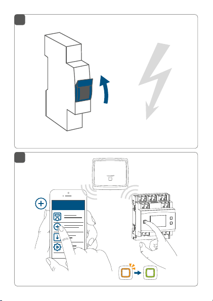
• Schalten Sie die Haussicherung wieder ein (s. Ab-
bildung 8), um den Anlernmodus des Geräts zu
aktivieren (s. „5.3 Anlernen“ auf Seite 27).
Nach der Installation und vor dem Anlernen des Geräts an die App stehen Ihnen bereits einfache Bedienfunktionen (z. B. für Testzwecke) direkt am Gerät zur Verfügung („6 Bedienung“ auf Seite 29).
Die kleinste anwählbare Dimmstufe muss so eingestellt sein, dass das angeschlossene Leuchtmittel
in dieser Betriebsart noch sichtbar leuchtet. Diese
kleinste Dimmstufe ist auf einen Wert von 5 % (Re
ferenzwert für eine 25-W-Glühlampe). voreingestellt. Sollten Sie Glühlampen mit anderen Leistungen oder keine Glühlampen (sondern z. B.
LED-Lampen) verwenden, kann es notwendig sein,
den Parameter entsprechend zu ändern.
26
-
Page 27

Inbetriebnahme
5.3 Anlernen
Bitte lesen Sie diesen Abschnitt erst vollständig,
bevor Sie mit dem Anlernen beginnen.
Richten Sie zunächst Ihren Homematic IP Access
Point über die Homematic IP App ein, um weitere
Homematic IP Geräte im System nutzen zu können. Ausführliche Informationen dazu finden Sie
in der Bedienungsanleitung des Access Points.
Sie können das Gerät an den Access Point oder an
die Zentrale CCU2/CCU3 anlernen. Weitere Informationen dazu entnehmen Sie bitte dem Homematic IP Anwenderhandbuch (zu finden im Downloadbereich unter www.homematic-ip.com).
Damit das Gerät in Ihr System integriert und per kostenloser Homematic IP App gesteuert werden kann, muss es
an den Homematic IP Access Point angelernt werden.
Zum Anlernen des Geräts gehen Sie wie folgt vor:
• Önen Sie die Homematic IP App auf Ihrem
Smartphone.
• Wählen Sie den Menüpunkt „Gerät anlernen“ aus.
• Nach dem Einschalten der Haussicherung ist der
Anlernmodus des Aktors für 3 Minuten aktiv.
27
Page 28

Inbetriebnahme
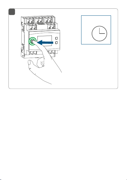
Sie können den Anlernmodus manuell für weitere
3 Minuten starten, indem Sie die Systemtaste (A)
kurz drücken (s. Abbildung 9).
• Das Gerät erscheint automatisch in der Homematic IP App.
• Zur Bestätigung geben Sie in der App die letzten
vier Ziern der Gerätenummer (SGTIN) ein oder
scannen Sie den QR-Code. Die Gerätenummer
finden Sie auf dem Aufkleber im Lieferumfang
oder direkt am Gerät.
• Warten Sie, bis der Anlernvorgang abgeschlossen
ist.
• Zur Bestätigung eines erfolgreichen Anlernvorgangs leuchtet die LED (A) grün. Das Gerät ist nun
einsatzbereit.
• Leuchtet die LED rot, versuchen Sie es erneut.
• Wählen Sie die gewünschte Lösung für Ihr Gerät
aus.
• Vergeben Sie in der App einen Namen für das Gerät und ordnen Sie es einem Raum zu.
28
Page 29

Bedienung
6 Bedienung
Über die folgenden Tasten stehen Ihnen einfache Bedienfunktionen direkt am Gerät zur Verfügung:
• Systemtaste (A)
• Channel-Taste (B)
• Select-Taste (C)
• externe Taster/Schalter (E)
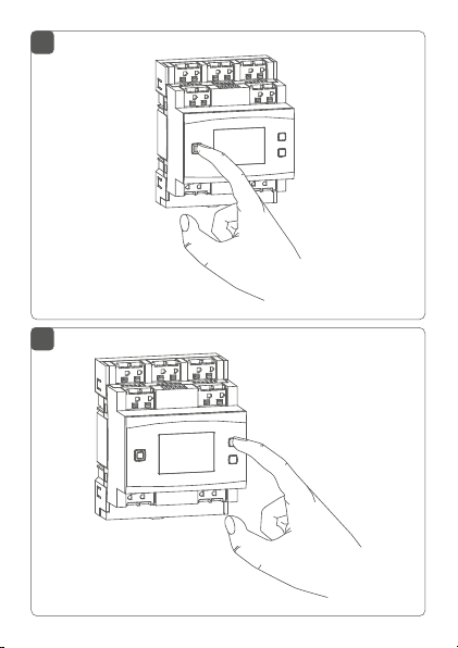
Systemtaste
Durch kurzes Drücken der Systemtaste (s. Abbildung 10)
können Sie die LCD-Hintergrundbeleuchtung aktivieren.
Channel-Taste
Durch kurzes Drücken der Channel-Taste (s. Abbildung
11) können Sie den gewünschten Kanal auswählen. Bei
jeder Betätigung wird ein Kanal weitergeschaltet.
Der ausgewählte Kanal wird durch Blinken des Symbols
gekennzeichnet. Der aktuelle Zustand des ausgewählten
Kanals (0 oder 100 %) wird im LC-Display angezeigt.
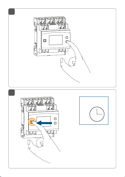
Select-Taste
Wenn Sie über die Channel-Taste einen Kanal ausgewählt
haben (s. Channel-Taste), können Sie durch kurzes Drücken der Select-Taste (s. Abbildung 12) den Zustand des
Ausgangskanals (z. B. 0 oder 100%) auswählen. Bei jeder
Betätigung wird ein Zustand weitergeschaltet. Bei den
Eingangskanälen wird durch Drücken der Select-Taste
ein kurzer Tastendruck für den ausgewählten Eingang
29
Page 30

Bedienung
simuliert. Die verknüpften Aktoren können so geschaltet
werden. Diese Funktion steht nicht zur Verfügung, wenn
der Eingang für Schaltkontakte konfiguriert ist.
Wenn Sie zuvor keinen Kanal ausgewählt haben, können
Sie durch kurzes Drücken der Select-Taste die folgenden
Anzeigen im LC-Display auswählen:
• Duty-Cycle des Dimmaktors (in %)
• Temperatur im Schaltaktor (in °C)
• Leere Anzeige
Das Dimmen des eingestellten Kanals ist nicht
über die Select-Taste möglich.
Externe Taster/Schalter
Mit den externen Tastern/Schaltern kann jeder Kanal direkt ein- bzw. ausgeschaltet und gedimmt werden.
• Kurzer Tastendruck des Tasters: Der zugehörige
Ausgang ändert seinen Zustand (0 oder 100 %).
• Langer Tastendruck des Tasters: Der zugehörige
Ausgang dimmt hoch (0 zu 100 %) oder runter
(100 zu 0 %).
• Umlegen des Schalters: Der zugehörige Ausgang
ändert seinen Zustand (0 oder 100 %).
30
Page 31

7 Fehlerbehebung
7.1 Fehlercodes und Blinkfolgen
Blinkcode/
LCD-Anzeige
Kurzes oranges
Blinken (alle
10 s)
6x langes rotes
Blinken
1x oranges
und 1x grünes
Leuchten
E10 Temperatur zu
Bedeutung Lösung
Anlernmodus
aktiv
Gerät defekt Achten Sie auf die
Testanzeige Nachdem die
hoch
Geben Sie die
letzten vier Ziern
der GeräteSeriennummer zur
Bestätigung ein (s.
„5.3 Anlernen“ auf
Seite 27).
Anzeige in Ihrer
App oder wenden
Sie sich an Ihren
Fachhändler.
Testanzeige
erloschen ist,
können Sie
fortfahren.
Reduzieren Sie die
angeschlossene Last
und lassen Sie das
Gerät abkühlen.
Fehlerbehebung
31
Page 32

Fehlerbehebung
E12* Kanal über-
lastet
Beachten Sie die
maximale Schaltleistung und reduzieren Sie die an den
betroenen Kanal
angeschlossene Last
entsprechend.
E13* Kommuni-
kation mit
Dimmerkanal
gestört
E17* Firmware-
Update für
Dimmerkanal
steht zur
Übertragung
an
Kontrollieren Sie die
Spannungsversorgung des betroenen Kanals.
Starten Sie den
Dimmaktor neu, um
die Übertragung des
Updates zu starten.
Ohne Update kann
der Kanal nicht weiter
verwendet werden.
*Diese Fehlercodes sind kanalbezogen. Sie werden immer im Wechsel mit der betroenen Kanalnummer angezeigt. Die Kanalnummer
wird mit einem vorangestellten C dargestellt (C1 bis C3).
7.2 Befehl nicht bestätigt
Bestätigt mindestens ein Empfänger einen Befehl nicht,
leuchtet zum Abschluss der fehlerhaften Übertragung
die LED (A) rot auf. Grund für die fehlerhafte Übertragung
kann eine Funkstörung sein (s. „10 Allgemeine Hinweise
32
Page 33

Fehlerbehebung
zum Funkbetrieb“ auf Seite 35). Die fehlerhafte Übertragung kann folgende Ursachen haben:
• Empfänger nicht erreichbar,
• Empfänger kann Befehl nicht ausführen (Lastausfall, mechanische Blockade etc.) oder
• Empfänger defekt.
7.3 Duty Cycle
Der Duty Cycle beschreibt eine gesetzlich geregelte Begrenzung der Sendezeit von Geräten im 868 MHz-Bereich. Das Ziel dieser Regelung ist es, die Funktion aller im
868 MHz-Bereich arbeitenden Geräte zu gewährleisten.
In dem von uns genutzten Frequenzbereich 868 MHz beträgt die maximale Sendezeit eines jeden Geräts 1 % einer
Stunde (also 36 Sekunden in einer Stunde). Die Geräte
dürfen bei Erreichen des 1 %-Limits nicht mehr senden,
bis diese zeitliche Begrenzung vorüber ist. Gemäß dieser
Richtlinie, werden Homematic IP Geräte zu 100 % normenkonform entwickelt und produziert.
Im normalen Betrieb wird der Duty Cycle in der Regel
nicht erreicht. Dies kann jedoch in Einzelfällen bei der Inbetriebnahme oder Erstinstallation eines Systems durch
vermehrte und funkintensive Anlernprozesse der Fall sein.
Eine Überschreitung des Duty Cycle-Limits wird durch
ein langes rotes Leuchten der LED (A) angezeigt und
kann sich durch temporär fehlende Funktion des Geräts
äußern. Nach kurzer Zeit (max. 1 Stunde) ist die Funktion
des Geräts wiederhergestellt.
33
Page 34

Wiederherstellung der Werkseinstellungen
8 Wiederherstellung der
Werkseinstellungen
Die Werkseinstellungen des Geräts können wiederhergestellt werden. Dabei gehen alle Einstellungen verloren.
Um die Werkseinstellungen des Geräts wiederherzustellen, gehen Sie wie folgt vor:
• Drücken Sie für 4 s auf die Systemtaste (A), bis
die LED (A) schnell orange zu blinken beginnt (s.
Abbildung 13).
• Lassen Sie die Systemtaste wieder los.
• Drücken Sie die Systemtaste erneut für 4 s, bis die
LED grün aufleuchtet (s. Abbildung 14).
• Lassen Sie die Systemtaste wieder los, um das
Wiederherstellen der Werkseinstellungen abzuschließen. Das Gerät führt einen Neustart durch.
9 Wartung und Reinigung
Das Gerät ist wartungsfrei. Überlassen Sie eine Wartung oder Reparatur einer Fachkraft.
Schalten Sie vor Ausbau des Geräts unbedingt die
Netzspannung frei (Sicherungsautomat abschalten)! Arbeiten am 230 V-Netz dürfen nur von einer Elektro-Fachkraft (nach VDE 0100) erfolgen.
34
Page 35

Allgemeine Hinweise zum Funkbetrieb
Reinigen Sie das Gerät mit einem weichen, sauberen,
trockenen und fusselfreien Tuch. Verwenden Sie keine
lösemittelhaltigen Reinigungsmittel, das Kunststogehäuse und die Beschriftung können dadurch angegrien
werden.
10 Allgemeine Hinweise zum Funk-
betrieb
Die Funk-Übertragung wird auf einem nicht exklusiven
Übertragungsweg realisiert, weshalb Störungen nicht
ausgeschlossen werden können. Weitere Störeinflüsse
können hervorgerufen werden durch Schaltvorgänge,
Elektromotoren oder defekte Elektrogeräte.
Die Reichweite in Gebäuden kann stark von der
im Freifeld abweichen. Außer der Sendeleistung
und den Empfangseigenschaften der Empfänger
spielen Umwelteinflüsse wie Luftfeuchtigkeit neben baulichen Gegebenheiten vor Ort eine wichtige Rolle.
Hiermit erklärt die eQ-3 AG, Maiburger Str. 29, 26789
Leer, Deutschland, dass der Funkanlagentyp Homematic IP HmIP-DRDI3 der Richtlinie 2014/53/EU entspricht. Der vollständige Text der EU-Konformitätserklärung ist unter der folgenden Internetadresse verfügbar:
www.homematic-ip.com
35
Page 36

Technische Daten
11 Technische Daten
Geräte-Kurzbezeichnung:
Versorgungsspannung: 230 V~/50 Hz
Stromaufnahme: 0,9 A max. (Ausgang Ka-
Leistungsaufnahme
Ruhebetrieb: 0,5 W typ. (Displaybe-
Kanal 1 bis 2
Versorgungsspannung: 230 V~/50 Hz
Stromaufnahme: 0,88 A
Leistungsaufnahme
im Ruhebetrieb: 0,4 W
Kanal 1 bis 3
Minimallast: 3 VA
Maximale Schaltleistung: 200 VA
Dimmverfahren: Phasenabschnitt
Kontaktart: Halbleiterschaltelement,
Verlustleistung des Geräts
für Wärmeberechnung: max. 7,5 W
Leitungsart und -querschnitt: starre und flexible Leitung,
Installation: auf Tragschiene (Hut-
36
HmIP-DRDI3
nal3: 200 VA)
leuchtung aus, Ausgang
Kanal 3 aus)
ɛ-Kontakt
0,75-2,5 mm²
schiene, DIN-Rail) gemäß
Page 37

Technische Daten
Schutzart: IP20
EN60715
Umgebungstemperatur: -5 bis +40 °C
Abmessungen (B x H x T): 72 x 90 x 69 mm (4 TE)
Gewicht: 200 g
Funk-Frequenzband: 868,0-868,60 MHz
869,4-869,65 MHz
Max. Funk-Sendeleistung: 10 dBm
Empfängerkategorie: SRD category 2
Typ. Funk-Freifeldreichweite: 190 m
Duty Cycle: < 1 % pro h/< 10 % pro h
Technische Änderungen vorbehalten.
Lastart Kanal 1-3
Glühlampenlast 200 W
Lampen mit internem Vorschaltge-
rät (LED/Kompaktleuchtstoampe)
100 W
HV-Halogenlampen 200 W
Elektronische Transformatoren für
NV-Halogenlampen
200 W
37
Page 38

Technische Daten
Entsorgungshinweis
Gerät nicht im Hausmüll entsorgen! Elektronische Geräte sind entsprechend der Richtlinie
über Elektro- und Elektronik-Altgeräte über die
örtlichen Sammelstellen für Elektronik-Altgeräte
zu entsorgen.
Konformitätshinweis
Das CE-Zeichen ist ein Freiverkehrszeichen, das
sich ausschließlich an die Behörden wendet und
keine Zusicherung von Eigenschaften beinhaltet.
Bei technischen Fragen zum Gerät wenden Sie
sich bitte an Ihren Fachhändler.
38
Page 39

Package contents
Quantity Description
1 Homematic IP Dimming Actuator
1 User manual
Documentation © 2019 eQ-3 AG, Germany
All rights reserved. Translation from the original version in German. This manual may not be reproduced in any format, either in
whole or in part, nor may it be duplicated or edited by electronic,
mechanical or chemical means, without the written consent of
the publisher.
Typographical and printing errors cannot be excluded. However,
the information contained in this manual is reviewed on a regular
basis and any necessary corrections will be implemented in the
next edition. We accept no liability for technical or typographical
errors or the consequences thereof.
All trademarks and industrial property rights are acknowledged.
Printed in Hong Kong
Changes may be made without prior notice as a result of technical advances.
154436 (web)
Version 1.1 (05/2020)
for DIN rail mount – 3 channels
39
Page 40

Table of Contents
1 Information about this manual....................................41
2 Hazard information ........................................................41
3 Function and device overview ....................................47
4 General system information ....................................... 49
5 Start-up ........................................................................... 49
5.1 Installation instructions ..................................................... 49
5.2 Mounting and installation ..................................................51
5.3 Teaching-in ..........................................................................54
6 Operation .........................................................................56
7 Troubleshooting .............................................................58
7.1 Error codes and flashing sequences .............................. 58
7.2 Command not confirmed ................................................. 59
7.3 Duty cycle ........................................................................... 60
8 Restore factory settings ................................................ 61
9 Maintenance and cleaning ........................................... 61
10 General information about radio operation .............62
11 Technical specifications ................................................63
40
Page 41

Information about this manual
1 Information about this manual
Please read this manual carefully before beginning
operation with your Homematic IP component. Keep the
manual so you can refer to it at a later date if you need to.
If you hand over the device to other persons for use, hand
over this manual as well.
Symbols used:
Attention!
This indicates a hazard.
Please note: This section contains important
additional information.
2 Hazard information
Do not open the device. It does not contain any
parts that can be maintained by the user. There is
a risk of electric shock if the device is opened. If
you have any doubts, have the device checked by
an expert.
For safety and licensing reasons (CE),
unauthorized change and/or modification of the
device is not permitted.
41
Page 42

Hazard information
Do not use the device if there are signs of damage
to the housing, control elements or connecting
sockets, for example. If you have any doubts,
have the device checked by an expert.
The device may only be operated in dry and dustfree environment and must be protected from
the eects of moisture, vibrations, solar or other
methods of heat radiation, excessive cold and
mechanical loads.
The device is not a toy; do not allow children to
play with it. Do not leave packaging material lying
around. Plastic films/bags, pieces of polystyrene,
etc. can be dangerous in the hands of a child.
We do not assume any liability for damage to
property or personal injury caused by improper
use or the failure to observe the hazard
information. In such cases, any claim under
warranty is extinguished! For consequential
damages, we assume no liability!
The actuator is part of the building installation.
The relevant national standards and directives
must be taken into consideration during planning
and set-up. The device has been designed solely
for operation on a 230V/50 Hz AC supply.
42
Page 43

Hazard information
Only qualified electricians (to VDE 0100) are
permitted to carry out work on the 230 V mains.
Applicable accident prevention regulations must
be complied with whilst such work is being
carried out. To avoid electric shocks from the
device, please disconnect the
the miniature circuit-breaker).
mains voltage (trip
Non-compliance
with the installation instructions can cause fire or
introduce other hazards.
No SELV/PELV circuits may be connected to the
terminals of the inputs and outputs, including the
extension inputs.
When connecting to the device terminals, take
the permissible cables and cable cross sections
into account.
Connected loads require sucient insulation.
Exceeding this capacity could lead to the
destruction of the device, fires or electric shocks.
Please take the technical data
(in particular the
maximum permissible switching capacity of the
load circuits and the type of load to be connected)
into account before connecting a load. Do
exceed the capacity specified for the device.
not
43
Page 44

Hazard information
For secure operation, the device has to be
installed in a power distribution panel according
to VDE 0603, DIN 43871 (low-voltage subdistribution board), DIN 18015-x. The installation
must be carried out on a mounting rail (DIN rail)
according to EN 60715. Installation and wiring
have to be performed according to VDE 0100
(VDE 0100-410, VDE 0100-510 etc.). Please
consider the technical connection requirements
(TAB) of your energy supplier.
Before installation and connection of the device,
mains voltage must be disconnected and live
parts in the surrounding must be covered.
Risk of electric shock. Device has not been
designed to support safety disconnection. Also in
case of disconnected output, the load is not
isolated from the mains.
Do not connect lights with integrated dimmer.
Device may be damaged.
Risk of electric shock. Before starting to work on
the device or exchanging lamps, disconnect
mains voltage and switch o the miniature
circuit-breaker.
44
Page 45

Hazard information
The dimming actuator is only suitable for light
bulbs and high-voltage and low-voltage halogen
lamps with electronic transformers as well as
dimmable LED lamps!
Do not connect LED or compact fluorescent
lamps which are not expressly suitable for
dimming. Device may be damaged.
For operation with electronic ballasts, only use
transformers that meet the requirements of DIN
EN 61347-1 and DIN EN 61047.
Please only connect ohmic and capacitive lamp
loads to the dimming actuator, and no televisions,
R,C
computers, motors etc.
In order to avoid changes in the level of
brightness, the device is able to detect ripple
control signals. However, short-time flickering of
the light source due to ripple control signals
cannot be completely excluded.
45
Page 46

Hazard information
Devices with electronic power supply units (e.g.
high voltage LED light sources) are no ohmic
loads. They can generate inrush currents with
more than 100 A. Switching such kind of loads
may lead to premature wear of the actuator. In
such cases, we recommend to use switch-on
current limiters at the switching outputs.
The device may only be operated within domestic
environment, in business and trade areas as well
as in small enterprises.
If you use the device/system in a security
application it has to be operated in connection
with an UPS (uninterruptible power supply) in
order to bridge possible power failure.
Using the device for any purpose other than that
described in this operating manual does not fall
within the scope of intended use and shall
invalidate any warranty or liability.
46
Page 47

Function and device overview
3 Function and device overview
The Homematic IP Dimming Actuator – 3 channels
can be easily installed on a DIN rail within a distribution
board. Once installed, it switches and dims connected
luminaries via three independent channels.
In the Homematic IP system, the dimming actuator can
switch and dim the connected luminaries comfortably via
connected wireless push-buttons, remote controls or via
the free Homematic IP Smartphone app. Furthermore,
direct operation can be realised via connected
conventional push-buttons or switches.
The dimming actuator enables dimming of
• normal incandescent lamps,
• high-voltage halogen lamps,
• low-voltage halogen lamps with electronic
transformers,
• dimmable energy-saving lamps
• dimmable LED lamps
*1
The usable dimming range is usually extremely restricted.
*2
It is not guaranteed that the dimming behaviour will be
performed correctly with any kind of LED lamps.
*2
*1
and
.
47
Page 48

Function and device overview
1 1
1
1
1
RX
1 1
RX
TX
1 1
Device overview (see figure 1):
(A) System button (teach-in button and LED)
(B) Channel button
(C) Select button
(D) LC display
(E) Connecting terminal for push-button/switch
channel 1-3
(F) Connecting
terminals for phase conductor (channel
1 and 2)
(G) DIN rail lock
Connecting terminals for phase conductor (power
(H)
supply/channel 3)
(I) Connecting terminal neutral conductor
(J) Connecting terminals for the consumer (load)
Display overview (see figure 1):
Symbol Meaning
Channel switched on
Channel switched o
Input not activated
Input activated
Receiving data
Transmitting data
48
Percentage (indicated, if switching status
or duty cycle are displayed)
Temperature indication (indicated, if
temperature is displayed)
Page 49

General system information
4 General system information
This device is part of the Homematic IP smart home
system and works with the Homematic IP radio protocol.
All devices of the system can be configured comfortably
and individually with the Homematic IP smartphone
app. Alternatively, you can operate the Homematic IP
devices via the Central Control Unit CCU2/CCU3 or in
connection with various partner solutions. The available
functions provided by the system in combination with
other components are described in the Homematic IP
User Guide. All current technical documents and updates
are provided at www.homematic-ip.com.
5 Start-up
5.1 Installation instructions
Before installation, please note the device
number (SGTIN) labelled on the device as well as
the exact application purpose in order to make
later allocation easier. You can also find the
device number on the QR code sticker supplied.
Please note! Only to be installed by persons with
the relevant electro-technical knowledge and
experience!*
49
Page 50

Start-up
Incorrect installation can put
• your own life at risk;
• and the lives of other users of the electrical system.
Incorrect installation also means that you are running the
risk of serious damage to property, e.g. because of a fire.
You may be personally liable in the event of injuries or
damage to property.
Contact an electrical installer!
*Specialist knowledge required for installation:
The following specialist knowledge is particularly important during
installation:
• The “5 safety rules” to be used:
Disconnect from mains; Safeguard from switching on
again; Check that system is de-energised; Earth and
short circuit; Cover or cordon o neighbouring live parts;
• Select suitable tool, measuring equipment and, if
necessary, personal safety equipment;
• Evaluation of measuring results;
• Selection of electrical installation material for
safeguarding shut-o conditions;
• IP protection types;
• Installation of electrical installation material;
• Type of supply network (TN system, IT system, TT
system) and the resulting connecting conditions
(classical zero balancing, protective earthing, required
additional measures etc.).
Please observe the hazard information in section
“2 Hazard information” on page 41 during
installation.
50
Page 51

Start-up
Please note the insulation stripping length of the
conductor to be connected, indicated on the
device.
Permitted cable cross sections for connecting to the
switch actuator are:
rigid cable [mm2] flexible cable
without ferrule [mm2]
0.75.-2.5 0.75.-2.5
5.2 Mounting and installation
Please read this entire section before starting to
install the device.
The load current circuits have to be secured by a
cable protection switch in accordance with
EN60898-1 (tripping characteristic B or C, max.
16 A rated current, min. 6kA interrupting rating,
energy limiting class 3).
To install the dimming actuator on a DIN rail within a
distribution board, please proceed as follows:
• Disconnect the power distribution panel from the
mains (see figure 2) and, if necessary, cover any
live parts (see safety rules).
• Remove the cover from the power distribution
panel.
51
Page 52

Start-up
• Place the dimming actuator onto the DIN rail (see
fig. 3). Make sure that you can read the letters on
the device and display and that the connecting
terminals of channel 1 and 3 are at the top.
• Make sure that the catch spring (G) engages
properly and that the device is securely seated on
the rail (see figure 4).
• Wire the device according to the connecting
diagrams in figure 6 or 7.
• Connect the phase conductor to the
corresponding terminals (F and H), the dimmed
phase (to the consumer) to terminal (J) as well
as the neutral conductor to the terminals (I) (see
figure 6+7). You can connect any types of phase
conductors (L1, L2, L3).
The self-supply of the dimming actuator as well
as the supply of the third channel are established
via terminals L/3L and N/3N.
The connections of the neutral conductor (I) are
not connected to each other within the device.
Therefore, all three terminals (1N, 2N, N/3N) must
be connected to the neutral conductor. If three
lamp circuits are fused via separate residualcurrent circuit breakers, separate neutral
conductors must be connected as well.
52
Page 53

Start-up
The phase conductor connection is marked with
an arrow pointing to the centre of the device, the
switched phase conductor with an arrow pointing
towards outside. To connect or loosen the
conductor, the white actuation lever at the top of
the clamp has to be pressed (see figure 5).
The network terminals may be used only for
connecting the power supply to the device or for
connecting loads to the device.
The connection
(looping through) of conductors via the network
terminals of the device to other devices is not
permitted!
• Connect external push-buttons or switches to
connecting terminal IN1 to IN3 (E) (see fig. 7):
• Replace the cover of the power distribution panel.
• Switch the fuse of the power circuit on again (see
figure 8) to activate the teach-in mode of the
device (see “5.3 Teaching-in” on page 54).
After installation and before connecting the device
to the app, basic operating functions (e.g. for test
purposes) are available directly on the device (“6
Operation” on page 56).
53
Page 54

Start-up
The lowest selectable dimming level must be set
so that the connected lamp is still visibly
illuminated in this operating mode. The lowest
dimming level is preset to a value of 5 % (reference
value for a 25 W incandescent lamp). When using
incandescent lamps with other wattages or no
incandescent lamps (like LED lamps, for example),
it may be necessary to change the parameter
accordingly.
5.3 Teaching-in
Read this entire section before starting the
teach-in procedure.
First set up your Homematic IP Access Point via
the Homematic IP app to enable operation of
other Homematic IP devices within your system.
For further information, refer to the operating
manual of the Access Point.
You can connect the device either to the Access
Point or to the Homematic Central Control Unit
CCU2/CCU3. For detailed information, refer to
the Homematic IP User Guide, available for
download in the download area of
www.homematic-ip.com.
54
Page 55

Start-up
To integrate the device into your system and to enable
control via the free Homematic IP app, you must teach-in
the device to your Homematic IP Access Point first.
To teach-in the device, please proceed as follows:
• Open the Homematic IP app on your smartphone.
• Select the menu item “Teach-in device”.
• After power supply is established, the teach-in
mode will be active for 3 minutes.
You can manually start the teach-in mode for
another 3 minutes by pressing the system button
(A) briefly (see figure 9).
• Your device will automatically appear in the
Homematic IP app.
• To confirm, enter the last four digits of the device
number (SGTIN) in your app or scan the QR code.
Therefore, see the sticker supplied or attached to
the device.
• Wait until the connection is completed.
• If connecting was successful, the LED (A) lights
up green. The device is now ready for use.
• If the LED lights up red, please try again.
• Select the desired solution for your device.
• In the app, give the device a name and allocate
it to a room.
55
Page 56

Operation
6 Operation
Via the following push-buttons, simple operating
functions are available directly on the device:
• system button (A)
• channel button (B)
• select button (C)
• external push-buttons/switches (E)
System button
By pressing the system button briefly (see figure 10), you
can activate the LCD background light.
Channel button
By pressing the channel button briefly (see figure 11) you
can select the desired channel. With each button press,
you can switch to the next channel.
The selected channel is indicated by the flashing symbol.
The current state of the selected channel (0 or 100 %) is
indicated on the display.
Select button
After selecting a channel via the channel button (see
‘Channel button’), you can select the status of the output
channel by briefly pressing the select button (see figure
12) (e.g. 0 or 100%). With a button press, you can switch
to the next status. For the input channels, pressing the
Select key simulates a short button press for the selected
input channel. Connected actuators can be switched.
56
Page 57

Operation
This function is not available if the input has been
configured for switch contacts.
If you have not selected a channel previously, you can
select the following options in the LC display by pressing
the Select button briefly:
• Duty cycle of the dimming actuator (in %)
• Temperature inside switch actuator (in °C)
• Empty display
It is not possible to dim the set channel using the
“Select” key.
External push-button/switch
With external push-buttons/switches, each channel can
be directly switched on or o or dimmed.
• Short button press of the push-button: The
corresponding channel changes its status (0 or
100 %).
• Long button press of the push-button: The
corresponding output dims up (0 to 100%) or
down (100 to 0%).
• Turning over the switch: The corresponding
channel changes its status (0 or 100 %).
57
Page 58

Troubleshooting
7 Troubleshooting
7.1 Error codes and flashing sequences
Flashing code /
LC display
Short orange
flashing (every
10 s)
6x long red
flashing
1x orange and
1 x green
lighting
E10 Temperature
58
Meaning Solution
Teach-in
mode active
Device
defective
Test display Once the test
too high
Enter the last four
numbers of the
device serial number
to confirm (see “5.3
Teaching-in” on
page 54).
Have a look at
your app for error
message or contact
your retailer.
display has stopped,
you can continue.
Reduce the
connected load and
let the device cool
down.
Page 59

Troubleshooting
E12* Channel
overloaded
Observe the
maximum switching
capacity and reduce
the load connected
to the channel
accordingly.
E13* Communi-
cation failure
with dimming
channel
E17* Firmware
update for
dimming
channel
available for
transmission
Check the power
supply of the
corresponding
channel.
Restart the dimming
actuator to begin
with the transfer of
the update. Without
update, the channel
is no longer available
for operation.
*These error codes are channel-related. They are always displayed
alternating with the relevant channel number. The channel number
is displayed with a prefix C (C1 to C3).
7.2 Command not confirmed
If at least one receiver does not confirm a command,
the device LED (A) lights up red at the end of the failed
transmission process. The failed transmission may be
caused by radio interference (see “10 General information
about radio operation” on page 62). The failed
59
Page 60

Troubleshooting
transmission may also be caused by the following:
• Receiver cannot be reached.
• Receiver is unable to execute the command (load
failure, mechanical blockade, etc.).
• Receiver is defective.
7.3 Duty cycle
The duty cycle is a legally regulated limit of the
transmission time of devices in the 868 MHz range. The
aim of this regulation is to safeguard the operation of all
devices working in the 868 MHz range.
In the 868 MHz frequency range we use, the maximum
transmission time of any device is 1% of an hour (i.e. 36
seconds in an hour). Devices must cease transmission
when they reach the 1% limit until this time restriction
comes to an end. Homematic IP devices are designed
and produced with 100% conformity to this regulation.
During normal operation, the duty cycle is not usually
reached. However, repeated and radio-intensive teachin processes mean that it may be reached in isolated
instances during start-up or initial installation of a system.
If the duty cycle is exceeded, this is indicated by one long
red lighting of the device LED (A) , and may manifest itself
in the device temporarily working incorrectly. The device
starts working correctly again after a short period (max.
1 hour).
60
Page 61

Restore factory settings
8 Restore factory settings
The factory settings of the device can be restored.
If you do this, you will lose all your settings.
To restore the factory settings of the device, proceed as
follows:
• Press and hold down the system button (A) for 4
seconds until the LED (A) quickly starts flashing
orange (see figure 13).
• Release the system button.
• Press and hold down the system button again
for 4 seconds, until the LED lights up green (see
figure 14).
• Release the system button to finish the procedure.
The device will perform a restart.
9 Maintenance and cleaning
The product does not require any maintenance.
Enlist the help of an expert to carry out any
maintenance or repairs.
The mains voltage must be disconnected before
the device is removed (trip the miniature circuitbreaker). Only qualified electricians (to VDE 0100)
are permitted to carry out work on the 230 V
mains.
61
Page 62

General information about radio operation
Clean the device using a soft, lint-free cloth that is clean
and dry. Do not use any detergents containing solvents,
as they could corrode the plastic housing and label.
10 General information about radio
operation
Radio transmission is performed on a non-exclusive
transmission path, which means that there is a possibility
of interference occurring. Interference can also be
caused by switching operations, electrical motors or
defective electrical devices.
The range of transmission within buildings can
dier greatly from that available in the open air.
Besides the transmitting power and the reception
characteristics of the receiver, environmental
factors such as humidity in the vicinity have an
important role to play, as do on-site structural/
screening conditions.
Hereby, eQ-3 AG, Maiburger Str. 29, 26789 Leer/Germany
declares that the radio equipment type Homematic IP
HmIP-DRDI3 is in compliance with Directive 2014/53/
EU. The full text of the EU declaration of conformity
is available at the following internet address:
www.homematic-ip.com
62
Page 63

Technical specifications
11 Technical specifications
Device short name:
Supply voltage: 230 V~/50 Hz
Current consumption: 0.9 A max. (output
Standby power consumption: 0.5 W typically (display
Channel 1 to 2
Supply voltage: 230 V~/50 Hz
Current consumption: 0.88 A
Standby power consumption: 0.4 W
Channel 1 to 3
Minimum load: 3 VA
Maximum switching capacity: 200 VA
Dimming method: Reverse phase control
Contact type: Semiconductor switching
Power loss of the device
for thermal calculation: 7.5 W max.
Cable type and cross section: rigid and flexible cable,
Installation: mounting rail (DIN rail)
Degree of protection: IP20
Ambient temperature: -5 to +40 °C
Dimensions (W x H x D): 72 x 90 x 69 mm
HmIP-DRDI3
channel 3: 200 VA)
lights o, output channel
3 o)
element, ɛ contact
0.75-2.5 mm²
according to EN 60715
63
Page 64

Technical specifications
Weight: 200 g
(4 WM width)
Radio frequency band: 868.0-868.60 MHz
869.4-869.65 MHz
Maximum radiated power: 10 dBm
Receiver category: SRD category 2
Typ. open area RF range: 190 m
Duty cycle: < 1 % per h/< 10 % per h
Subject to technical changes.
Load type Channel 1-3
incandescent lamp load 200 W
self-ballasted lamps
(LED/compact fluorescent lamp)
100 W
HV halogen lamps 200 W
electronic transformers for
NV halogen lamps
200 W
Instructions for disposal
Do not dispose of the device with regular
domestic waste! Electronic equipment must be
disposed of at local collection points for waste
electronic equipment in compliance with the
Waste Electrical and Electronic Equipment
Directive.
64
Page 65

Technical specifications
Information about conformity
The CE sign is a free trading sign addressed
exclusively to the authorities and does not
include any warranty of any properties.
For technical support, contact your specialist
dealer.
65
Page 66

Kostenloser Download der Homematic IP App!
Free download of the Homematic IP app!
Bevollmächtigter des Herstellers:
Manufacturer’s authorised representative:
eQ-3 AG
Maiburger Straße 29
26789 Leer / GERMANY
www.eQ-3.de
 Loading...