

Page 1
Installations- und Bedienungsanleitung
D
RS485 Busabschluss-Widerstand
HMW-Sys-Tm
RS485 Busabschluss-Widerstand
Hutschienenmontage
HMW-Sys-Tm-DR Seite 4 - 12
GB
Installation and Operating Manual
RS485 bus terminator
HMW-Sys-Tm
RS485 bus terminator
for mounting on DIN rails
HMW-Sys-Tm-DR Page 14 - 22
Page 2

1. Ausgabe Deutsch 07/2007
Dokumentation © 2007 eQ-3 Ltd., Hong Kong
Alle Rechte vorbehalten. Ohne schriftliche
Zustimmung des Herausgebers darf dieses
Handbuch auch nicht auszugsweise in irgendeiner
Form reproduziert werden oder unter Verwendung
elektronischer, mechanischer oder chemischer
Verfahren vervielfältigt oder verarbeitet werden.
Es ist möglich, dass das vorliegende Handbuch
noch drucktechnische Mängel oder Druckfehler
aufweist. Die Angaben in diesem Handbuch werden
jedoch regelmäßig überprüft und Korrekturen in
der nächsten Ausgabe vorgenommen. Für Fehler
technischer oder drucktechnischer Art und ihre
Folgen übernehmen wir keine Haftung.
Alle Warenzeichen und Schutzrechte werden
anerkannt.
Printed in Hong Kong
Änderungen im Sinne des technischen Fortschritts
können ohne Vorankündigung vorgenommen
werden.
75221 / V 1.0
2
Page 3

1. English edition 07/2007
Documentation © 2007 eQ-3 Ltd., Hong Kong
All rights reserved. No parts of this manual may
be reproduced or processed in any form using
electronic, mechanical or chemical processes in part
or in full without the prior explicit written permission
of the publisher.
It is quite possible that this manual has printing
errors or defects. The details provided in this manual
are checked regularly and corrections are done in
the next edition. We do not assume any liability for
technical or printing errors.
All registered trade marks and copyrights are
acknowledged.
Printed in Hong Kong
We reserve the right to make changes due to
technical advancements without prior notice.
75221 / V 1.0
3
Page 4

Inhaltsverzeichnis
1 Hinweise zu dieser Anleitung . . . . . . . . . . . . . 5
2 Gefahrenhinweise
3 Funktion
4 Allgemeine Systeminformation zu
HomeMatic . . . . . . . . . . . . . . . . . . . . . . . . . . . 9
5 Installation
6 Wartung und Reinigung
7 Technische Daten
4
. . . . . . . . . . . . . . . . . . . . . . 5
. . . . . . . . . . . . . . . . . . . . . . . . . . . . . . 6
. . . . . . . . . . . . . . . . . . . . . . . . . . . . 9
. . . . . . . . . . . . . . . . 11
. . . . . . . . . . . . . . . . . . . . . 12
Page 5
1 Hinweise zu dieser Anleitung
Lesen Sie diese Anleitung sorgfältig, bevor Sie ihre
HomeMatic Komponenten in Betrieb nehmen.
Bewahren Sie die Anleitung zum späteren
Nachschlagen auf!
Wenn Sie das Gerät anderen Personen zur
Nutzung überlassen, übergeben Sie auch diese
Bedienungsanleitung.
Benutzte Symbole:
Achtung! Hier wird auf eine Gefahr
hingewiesen.
Hinweis. Dieser Abschnitt enthält zusätzliche
wichtige Informationen!
2 Gefahrenhinweise
Der Betrieb des Gerätes ist ausschließlich an
24 V Gleichspannung zulässig.
Betreiben Sie das Gerät nur in Innenräumen und
vermeiden Sie den Einfluss von Feuchtigkeit, Staub
sowie Sonnen- oder andere Wärmebestrahlung.
5
Page 6

Öffnen Sie das Gerät nicht, es enthält keine durch
den Anwender zu wartenden Teile.
Beachten Sie die Installationsvorschriften für
Installationen in Verteilersystemen.
Beachten Sie beim Anschluss an die
Geräteklemmen die hierfür zulässigen Leitungen und
Leitungsquerschnitte.
3 Funktion
Beim Betrieb drahtgebundener HomeMatic
Komponenten ist ein Abschlusswiderstand
zwingend notwendig um den Bus auf den
richtigen Pegel zu bringen und damit eine sichere
Kommunikation zu gewährleisten.
6
Page 7
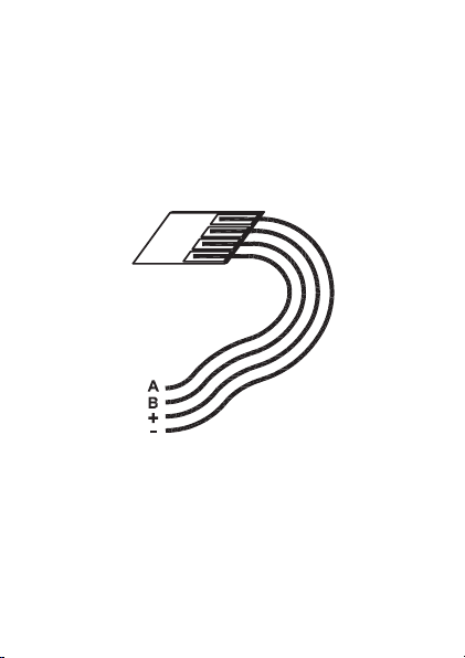
HMW-Sys-Tm
Die Montage des Moduls erfolgt an einer beliebigen
Stelle am Bus. Die Aderlängen des HMW-SysTm sind für den Anschluss an eines der RS485Hutschienenmodule optimiert.
A – Busanschluss A
B – Busanschluss B
+/- - Spannungsversorgung 24 V
7
Page 8
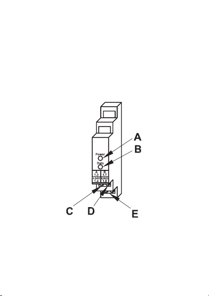
HMW-Sys-Tm-DR
Der Busabschlusswiderstand zur Hutschienenmontage
zeigt zusätzlich das Vorhandensein der Betriebsspannung für das HMW-System und die Übertragung
von Daten auf dem Bus mit Leuchtdioden an.
Die Montage des Moduls erfolgt auf einer StandardHutschiene innerhalb von Haus- und Unterverteilungen.
Es belegt dabei eine Montagebreite von 1 TE.
A – Kontrollleuchte Betriebsspannung
B – Kontrollleuchte Datenverkehr
C – Busanschluss A-Klemme
D – Busanschluss B-Klemme
E – Klemmen Spannungsversorgung 24 V
8
Page 9

4 Allgemeine Systeminformation
zu HomeMatic
Dieses Gerät ist Teil des HomeMatic
Haussteuersystems.
Weitere Anschlusshilfen entnehmen Sie bitte dem
HomeMatic Systemhandbuch.
Alle technischen Dokumente und Updates finden Sie
stets aktuell unter www.HomeMatic.com.
5 Installation
Voraussetzung für den Betrieb des
Moduls ist eine stabilisierte 24-VGleichspannungsversorgung. Hier empfiehlt
sich der Einsatz des Netzteils HMW-SysPS7-DR. Der Anschluss an den Bus und die
Versorgungsspannung kann an beliebiger Stelle im
Bus erfolgen.
Achten Sie darauf, dass die A- und die B-
Busleitung nicht vertauscht werden. Dies
kann zum Ausfall der Kommunikation führen. Achten
Sie beim Anschluss der Versorgungsspannung strikt
auf den polaritätsrichtigen Anschluss!
9
Page 10

HM-Sys-TM:
Schalten Sie die Busspannungsversorgung
ab. Schließen Sie den Abschlusswiderstand
an die Busklemmen und den
Spannungsversorgungsanschluss eines beliebigen
Moduls am Bus entsprechend nachfolgender
Anschlusstabelle an.
Ader Klemme
Schwarz GND
Rot + 24 V
Grün A
Gelb B
Lassen Sie keine offenen Leitungsenden am
Anschluss liegen!
HM-Sys-TM-DR:
Schalten Sie die Busspannungsversorgung
ab. Isolieren Sie die Drahtenden der
Stromversorgungsleitung und der Busleitung auf
eine Länge von 8 mm ab, ohne dabei die blanke
Ader zu verletzen. Beachten Sie die zugelassenen
Leitungsquerschnitte!
10
Page 11

Zugelassene Leitungsquerschnitte.
starre Leitung [mm2] flexible Leitung mit
Aderendhülse [mm2]
0,14 – 2,50 0,14 – 1,5
Setzen Sie das Modul auf die Hutschiene auf und
verriegeln Sie es mit der Schiene.
Achten Sie dabei darauf, dass die Rastfeder
komplett einrastet und das
Gerät fest auf der Schiene sitzt.
Verbinden Sie Busleitung und 24 V
Versorgungsleitung polrichtig gemäß
Klemmenbeschriftung auf dem Modul.
6 Wartung und Reinigung
Das Produkt ist wartungsfrei. Überlassen Sie eine
Reparatur einer Fachkraft.
11
Page 12

7 Technische Daten
HMW-Sys-Tm
Betriebsspannung: 24 V DC
Stromaufnahme: ca. 1 mA
Abm. (B x H x T): ca. 14 x 22 x 5 mm
HMW-Sys-Tm-DR
Betriebsspannung: 24 V DC
Stromaufnahme: max. 30 mA
Gehäuseabmessungen: Standard-
Entsorgungshinweis
Gerät nicht im Hausmüll entsorgen!
Elektronische Geräte sind entsprechend
der Richtlinie über Elektro- und ElektronikAltgeräte über die örtlichen Sammelstellen
für Elektronik-Altgeräte zu entsorgen.
Das CE-Zeichen ist ein Freiverkehrszeichen,
das sich ausschließlich an die Behörden
wendet und keine Zusicherung von Eigenschaften
beinhaltet.
12
Hutschienengehäuse mit
1 TE Breite
87 x 18 x 64 mm
(H x B x T)
Page 13

13
Page 14

Table of Contents
1 Information concerning these instructions . 15
2 Hazard information
3 Function
4 General system information on HomeMatic
5 Installation
6 Maintenance and cleaning
7 Technical specifications
14
. . . . . . . . . . . . . . . . . . . . . . . . . . . . . 16
. . . . . . . . . . . . . . . . . . . . 15
19
. . . . . . . . . . . . . . . . . . . . . . . . . . . 19
. . . . . . . . . . . . . . 21
. . . . . . . . . . . . . . . . 22
Page 15

1 Information concerning these
instructions
Read these instructions carefully before beginning
operation with your HomeMatic components.
Keep the instructions handy for later consultation!
Please hand-over the operating manual as well
when you hand-over the device to other persons
for use.
Symbols used:
Attention! This indicates a hazard.
Note. This section contains additional
important information!
2 Hazard information
Operating the device is only permitted with
24 V d.c. power.
This device is to be operated indoors only and keep
away from the influences of humidity, dust and
sunshine or other radiating heat sources.
15
Page 16

Do not open the device. It does not contain any
parts to be maintained by the user.
Observe the installation instructions for
installations in distribution systems.
Make sure that the specified wiring and wire crosssections are used when connecting to device
terminals.
3 Function
When operating HomeMatic components that must
be wired, a termination resistor is required to keep
the bus at the proper level and therefore guarantee
secure communication.
16
Page 17

HMW-Sys-Tm
Installing the module can be done anywhere on
the bus. The wire lengths of the HMW-Sys-Tm are
optimized for connecting to one of the RS485 DIN
rail modules.
A – Bus connection A
B – Bus connection B
+/- - Power supply 24 V
17
Page 18

HMW-Sys-Tm-DR
The bus termination resistor for mounting on DIN rails
also indicates the existence of the operational power
for the HMW system and the transmission of data on
the bus with LEDs.
The installation of the module is done on a standard
DIN rail within the main and sub-divisions.It occupies
an installation width of 1 unit.
A – Operating voltage indicator lamp
B – Data traffic indicator lamp
C – A-terminal bus connection
D – B-terminal bus connection
E – Terminal Power supply 24 V
18
Page 19

4 General system information on
HomeMatic
This device is a component of the HomeMatic Home
Control System.
Further information on connections are provided in
the HomeMatic System Manual.
All current technical documents and updates are
provided under www.HomeMatic.com.
5 Installation
The prerequisite for operating the module is a
stabilized 24 V d.c. supply voltage.
The use of an HMW-Sys-PS7-DR power supply is
recommended here.
The connection to the bus and the power supply
can be done in any position on the bus.
Make sure that the A and B bus lines
are not swapped. This could lead to the
communication failing. Be careful and make sure
that the polarity is correct when connecting the
supply voltage!
19
Page 20

HM-Sys-TM:
Switch the power supply to the bus off.
Connect the termination resistor to the bus terminals
and the power supply connection of any module on
the bus according to the following connection table.
Wire Terminal
Black GND
Red + 24 V
Green A
Yellow B
Do not leave any open wire ends around the
connection!
HM-Sys-TM-DR:
Switch the power supply to the bus off. Insulate the
wire ends of the power supply line and the bus line
to a length of 8 mm without damaging the actual
wire.
Observe the specified wire cross-sections!
20
Page 21

Permitted wire cross-sections.
Rigid wire [mm2] Flexible wire with end
0.14 – 2.50 0.14 – 1.5
Position the module on the DIN rail and lock it in
place.
Make sure that the spring latch is completely
latched and that the device is seated solidly
on the rail.
Connect the bus line and the 24 V supply line,
ensuring that the polarity is correct, according to the
terminal labeling on the module.
sleeve [mm2]
6 Maintenance and cleaning
This product is maintenance-free. Repairs are only
to be done by trained professionals.
21
Page 22

7 Technical specifications
HMW-Sys-Tm
Operating voltage: 24 V DC
Current consumption: approx. 1 mA
Dim. (W x H x D): approx. 14 x 22 x 5 mm
HMW-Sys-Tm-DR
Operating voltage: 24 V DC
Current consumption: max. 30 mA
Housing dimensions: Standard DIN rail
87 x 18 x 64 mm
(H x W x D)
Instructions for disposal
Do not dispose off the device as part of
household garbage! Electronic devices are
to be disposed of in accordance with the
guidelines concerning electrical and electronic
devices via the local collecting point for old
electronic devices.
The CE sign is a free trade sign addressed
exclusively to the authorities and does not
include any warranty of any properties.
22
housing with 1 TE wide
Page 23

23
Page 24

eQ-3 AG
Maiburger Straße 29
D-26789 Leer
www.eQ-3.com
 Loading...