


Installations- und
Bedienungsanleitung (S. 2)
Installation and
Operating Manual (p. 20)
RS485 Schließerkontakt 12 Eingänge
Hutschienmontage:
RS485 12-channel shutter contact
for mounting on DIN rails:
HMW-Sen-SC-12-DR

1. Ausgabe Deutsch 03/2009
Dokumentation © 2009 eQ-3 Ltd., Hong Kong
Alle Rechte vorbehalten. Ohne schriftliche Zustimmung des Herausgebers darf dieses Handbuch auch
nicht auszugsweise in irgendeiner Form reproduziert
werden oder unter Verwendung elektronischer, mechanischer oder chemischer Verfahren vervielfältigt
oder verarbeitet werden.
Es ist möglich, dass das vorliegende Handbuch
noch drucktechnische Mängel oder Druckfehler
aufweist. Die Angaben in diesem Handbuch werden
jedoch regelmäßig überprüft und Korrekturen in der
nächsten Ausgabe vorgenommen. Für Fehler technischer oder drucktechnischer Art und ihre Folgen
übernehmen wir keine Haftung.
Alle Warenzeichen und Schutzrechte werden anerkannt.
Printed in Hong Kong
Änderungen im Sinne des technischen Fortschritts
können ohne Vorankündigung vorgenommen
werden.
84666 / V 1.00
2

Inhaltsverzeichnis
1 Hinweise zu dieser Anleitung .............4
2 Gefahrenhinweise ......................4
3 Funktion ..............................6
4 Allgemeine Systeminformation
zu HomeMatic ......................... 7
5 Allgemeine Hinweise zum Bussystem ......7
5.1 Allgemeine Hinweise zur Installation .......7
5.2 Topologie des Bussystems ...............9
6 Installation ............................7
7 Funktions-Zuordnung der
Schaltkontakt-Eingänge ................14
7.1 Anlernen von Schaltkontakt-Eingängen ....14
7.2 Verwendung des Gerätes ............... 15
8 Wartung und Reinigung.................16
9 Technische Daten...................... 17
3
1 Hinweise zu dieser Anleitung
Lesen Sie diese Anleitung sorgfältig, bevor Sie ihre
HomeMatic-Komponenten in Betrieb nehmen.
Bewahren Sie die Anleitung zum späteren Nachschlagen auf!
Wenn Sie das Gerät anderen Personen zur Nutzung
überlassen, übergeben Sie auch diese Bedienungsanleitung.
Benutzte Symbole:
Achtung! Hier wird auf eine Gefahr hingewiesen.
Hinweis. Dieser Abschnitt enthält zusätzliche
wichtige Informationen!
2 Gefahrenhinweise
Die beschriebenen Geräte sind Teil einer
Gebäudeinstallation. Bei der Planung und
Errichtung von Elektrischen Anlagen sind die einschlägigen Normen und Richtlinien des Landes zu
beachten, in dem die Anlage installiert wird.
4
Der Betrieb des Gerätes ist ausschließlich mit einer
Gleichspannung von 24 V (Schutzkleinspannung)
zulässig.
Arbeiten in Installationsbereichen mit Netzspannung
dürfen nur durch eine Elektro-Fachkraft (nach VDE
0100) erfolgen. Dabei sind die geltenden Unfallverhütungsvorschriften zu beachten.
Bei Nichtbeachtung der Installationshinweise können Brand- oder andere Gefahren entstehen.
Betreiben Sie das Gerät nur in Innenräumen und
vermeiden Sie den Einfluss von Feuchtigkeit, Staub
sowie Sonnen- oder andere Wärmebestrahlung.
Öffnen Sie das Gerät nicht, es enthält keine
durch den Anwender zu wartenden Teile.
Beachten Sie beim Anschluss an die Geräteklemmen die hierfür zulässigen Leitungen und Leitungsquerschnitte.
Beachten Sie die Installationsvorschriften für
Installationen in Verteilersystemen.
5

3 Funktion
• 12Schaltkontakt-Eingänge.
• UmfangreicheKongurationsmöglichkeiten
über die HomeMatic-Zentrale.
NichtüchtigerSpeicherfürKongurationsdaten.
•
• MontageaufeinerStandard-Hutschieneinner-
halb von Vertei lungen.
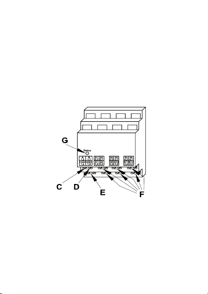
(C) - Bus A
(D) - Bus B
(E) – Busspannungsversorgung
(F) – Klemmen Schaltkontakt-Eingänge
(G) – Status LED
6

4 Allgemeine Systeminformation
zu HomeMatic
Dieses Gerät ist Teil des HomeMatic-Haussteuersystems.
AlleGerätewerdenmiteinerStandardkonguration
ausgeliefert. Darüber hinaus ist die Funktion des
Gerätes über ein Programmiergerät und Software
kongurierbar.WelcherweitergehendeFunktionsumfang sich damit ergibt, und welche Zusatzfunktionen sich im HomeMatic-System im Zusammenspiel
mit weiteren Komponenten ergeben, entnehmen Sie
bittedergesondertenKongurationsanleitungoder
dem HomeMatic-Systemhandbuch.
AlletechnischenDokumenteundUpdatesndenSie
stets aktuell unter www.HomeMatic.com.
5 Allgemeine Hinweise zum
Bussystem
5.1 Allgemeine Hinweise zur Installation
Grundsätzlich kann man die Anschlüsse der
HMW-Komponenten in zwei Gruppen einteilen. In
die Lastseite und in die Steuerseite (24-V- Span-
7

nungsversorgung, Taster- und Schaltereingänge,
RS485-Bus). Der Schließerkontakt-Sensor verfügt
aufgrund seiner Aufgabe, die Schaltzustände der
angeschlossenen Kontakte zu erfassen, lediglich
über die Steuerseite.
Steuerseite
Auf der Steuerseite kommt lediglich ungefährliche
Schutzkleinspannung zum Einsatz. Für die Verdrahtung der Steuerseite brauchen hier keine netzspannungsfesten Leitungen verwendet zu werden. Es
empehltsichdieVerwendungvonFernmelde-Installationsleitung oder vergleichbarer Steuerleitung.
Zu beachten ist allerdings, dass diese Leitungen
generell getrennt von jeglichen 230-V-führenden
Leitungen, entsprechend den VDE-Richtlinien, zu
verlegen sind. Dabei ist ein Mindestabstand von 8
mm zwischen beiden Leitungsarten zu beachten.
Beim Anschluss des RS485-Busses sind die
A-Klemmen (1.3), die B-Klemmen (1.7), die
24-V-Spannungs versorgung und die Masseklemmen
(1.8) der Module einer Unterverteilung (max.
127 Stück) jeweils miteinander zu verbinden.
Beim Einsatz mehrerer Module ist ein Busabschluss
erforderlich.
8

InformationenzumAnschlussndenSieinder
jeweiligen Bedienungsanleitung.
5.2 Topologie des Bussystems
Aus Gründen der Übersicht sollten die HMW-Komponenten immer gruppenweise in Unterverteilungen
montiert werden. Wie viele Unterverteilungen angemessen sind, hängt dabei von der Art und Größe
des zu realisierenden Projektes ab und ist individuell
festzulegen.
Es ist auf jeden Fall zu empfehlen, auf jeder Etage
mindestens eine Unterverteilung zu installieren. Bei
größeren Gebäuden kann es auch sinnvoll sein,
mehrere Verteilungen pro Etage (z. B. separat für
jeden Flur) vorzusehen. Entsprechend sind alle Lastund Steuerleitungen sternförmig zu den entsprechenden Unterverteilungen zu führen. Die Stromversorgung erfolgt über das Hutschienen-Netzteil
HMW-Sys-PS7-DR oder ein anderes, entsprechend
der Anzahl und Gesamtstromaufnahme aller
vorhandenen Module in der jeweiligen Unterverteilung dimensioniertes 24 V-Netzteil. Wenn eine
zentrale Programmierung und Steuerung über die
HomeMatic-Zentrale erfolgen soll, sollten die HMW-
9

Busleitungen der einzelnen Unterverteilungen sowie
die vom Steuer-PC bzw. einer Zentrale kommende
Leitung an einem unter räumlichen Gesichtspunkten
günstigen Ort zusammengeführt werden, um eine
Trennung der einzelnen Busabschnitte zu erreichen
und ggf. eine Fehlersuche zu vereinfachen. Üblicherweise ist dies der Raum, in dem die Zentrale des
HomeMatic-Systems installiert wird.
6 Installation
Beachten Sie die Installationsvorschriften für
Installationen in Verteilersystemen.
Setzen Sie das Hutschienengerät auf die Hutschiene
auf und verriegeln Sie es.
Achten Sie dabei darauf, dass die Rastfeder
komplett einrastet und das Gerät fest auf der
Schiene sitzt.
Isolieren Sie die Drahtenden der Leitungen zu den
Schaltkontakten, zum Netzteil und der Busleitung
auf eine Länge von 8 mm ab, ohne dabei die blanke
Ader zu verletzen. Beachten Sie die zugelassenen
Leitungsquerschnitte!
10
Vergewissern Sie sich, dass alle Anschlüsse
fest und sicher in den Installationsklemmen
xiertsind.
Verdrahten Sie die Hutschienenmodule zur Busspannungsversorgung (Klemmen 1.4 und 1.8) mit
dem Netzteil. Achten Sie dabei strikt auf den polaritätsrichtigen Anschluss an den Klemmen.
Schließen Sie die Schaltkontakte jeweils zwi-
schen GND (Klemme 1.8) und dem jeweiligen
Eingang (S1 bis S12, Klemmen 2.3, 2.4, 2.7, 2.8, 3.3,
3.4, 3.7, 3.8, 4.3, 4.4, 4.7, 4.8) an.
Die maximale Leitungslänge vom Schalt-
kontakt zum Modul ist je nach verwendeter
Leitung unterschiedlich. Es sollte jedoch eine Länge
von 50 m nicht überschritten werden. Es sind nur
Kontakte einzusetzen, die die in den technischen
Daten dieser Anleitung genannten Grenzwerte des
Kontaktwiderstandes aufweisen.
Niemals die Schaltkontakt-Eingänge mit
Spannungen beschalten!
11

Klemmenbelegung siehe nächste Seite
12

1.3 RS485-Bus (Bus A)
1.7 RS485-Bus (Bus B)
1.4 Spannungsversorgung 24 V / DC
1.8
Spannungsversorgung Masseanschluss
2.3 Schaltkontakt-Eingang S1
2.7 Schaltkontakt-Eingang S2
3.3 Schaltkontakt-Eingang S3
3.7 Schaltkontakt-Eingang S4
4.3 Schaltkontakt-Eingang S5
4.7 Schaltkontakt-Eingang S6
2.4 Schaltkontakt-Eingang S7
2.8 Schaltkontakt-Eingang S8
3.4 Schaltkontakt-Eingang S9
3.8 Schaltkontakt-Eingang S10
4.4 Schaltkontakt-Eingang S11
4.8 Schaltkontakt-Eingang S12
Zugelassene Leitungsquerschnitte
starre Leitung [mm2]
flexible Leitung mit
Aderendhülse [mm
0,14 – 2,50 0,14 – 1,5
2
]
13

7 Funktions-Zuordnung der
Schaltkontakt-Eingänge
Die 12 Schaltkontakt-Eingänge des
HMW-Sen-SC-12-DR lassen sich nur über die
HomeMatic-Zentrale anderen HomeMatic-Komponenten zuordnen, es sind keine direkten Verknüpfungen mit anderen Komponenten möglich.
Da dieses Gerät keine Bedienelemente besitzt,
erfolgtjeglicheBedienungundKongurationüber
die Bedienoberfläche „HomeMatic WebUI”, die als
Web-Anwendersoftware auf der als Web-Server
arbeitenden HomeMatic-Zentrale läuft.
Nach dem nachfolgend beschriebenen Anlernvorgang steht das Gerät im HomeMatic-System zur
Verfügung.
7.1 Anlernen von Schaltkontakt-Eingängen
Für das Anlernen des Gerätes bzw. dessen angeschlossener Schaltkontakte sind zwei Methoden
verfügbar:
Die erste Möglichkeit besteht darin, dass nach der
Installation einer der angeschlossenen Schaltkon-
14

takte erstmalig geschlossen wird. Damit lernt die
HomeMatic-Zentrale, die den RS485-Bus ständig
abfragt, das Gerät automatisch an.
Die zweite Möglichkeit besteht darin, den Anlernmodus für HomeMatic-Wired-Geräte (Variante 2)
über die Funktion „Geräte anlernen” -> „Geräte
suchen” der Bedienoberfläche „HomeMatic WebUI“
zu aktivieren.
7.2 Verwendung des Gerätes
NachdemAnlernenundderKongurationander
HomeMatic-Zentrale kann das Gerät zur Erstellung
von Programmabläufen (mit der HomeMatic WebUI)
verwendet werden. Diese Programmabläufe sind
zentral gesteuerte Geräteverknüpfungen, bei denen
zwei oder mehrere Geräte über die zwischengeschaltete HomeMatic-Zentrale miteinander kommunizieren. Sender und Empfänger kommunizieren
jeweils nur mit der Zentrale, es besteht keine direkte
Verbindung zwischen den einzelnen Geräten. Die
Zentrale übernimmt die gesamte Steuerung. Daher
ist das Gerät in den zugehörigen Kanallisten zur
Erstellung einer solchen Verknüpfung nicht gelistet.
Da sich aber alle Funktionalitäten einer solchen
direkten Verknüpfung auch mittels einer oben be-
15

schriebenen Zentralenverknüpfung abbilden lassen,
stellt dies keine Einschränkung dar.
Ist bei der Anwendung nur die Information über den
aktuellen Zustand eines Schaltkontaktes interessant, so kann dieser im Untermenü „Status“ der
HomeMatic WebUI abgerufen werden.
8 Wartung und Reinigung
Das Produkt ist wartungsfrei. Überlassen Sie eine
Reparatur einer Fachkraft.
16

9 Technische Daten
Kommunikation:
– Schnittstelle: RS485-Bus
– Protokoll: HomeMatic Wired
Steuereingänge: 12 unabhängige Kontakt-
(Schutzkleinspannung)
Grenzwerte des Kontaktwiderstandes:
–
Kontakt geöffnet: R ≥ 80 kΩ
–
Kontakt geschlossen: R ≤ 5 kΩ
Spannungsversorgung: 24 V (20 V bis 30 V) /
DC (SELV)
Stromaufnahme: 20 mA
Anschlüsse: Klemmanschlüsse
Zugelassene Leitungsquerschnitte für
–
starre Leitung: 0,14 mm² bis 2,50 mm²
–
flexible Leitung mit
Aderendhülse: 0,14 mm² bis 1,5 mm²
Montageart: TS35Prolschienelt.
Gehäuseabmessungen: 87 x 72 x 65 mm (H x B x T)
Standard-Hutschienen-
eingänge, massebezogen
EN 50022 (Standard Hutschiene, DIN Rail)
gehäuse mit 4 TE Breite
17

Entsorgungshinweis:
Gerät nicht im Hausmüll entsorgen! Elektro-
nische Geräte sind entsprechend der Richt-
linie über Elektro- und Elektronik-Altgeräte
über die örtlichen Sammelstellen für Elektronik-Altgeräte zu entsorgen.
Das CE-Zeichen ist ein Freiverkehrszeichen,
das sich ausschließlich an die Behörden
wendet und keine Zusicherung von Eigenschaften
beinhaltet.

19

1st English edition 03/2009
Documentation © 2009 eQ-3 Ltd. Hong Kong
All rights reserved. No parts of this manual may
be reproduced or processed in any form using
electronic, mechanical or chemical processes in part
or in full without the prior explicit written permission
of the publisher. It is quite possible that this manual
has printing errors or defects. The details provided
in this manual are checked regularly and corrections
are done in the next edition. We do not assume any
liability for technical or printing errors.
All registered trade marks and copyrights are
acknowledged.
Printed in Hong Kong We reserve the right to make
changes due to technical advancements without
prior notice.
84666 / V 1.00
20

Table of contents
1 Information about this manual ............4
2 Hazard information .....................4
3 Function .............................. 6
4 General system information
about HomeMatic ......................7
5 General information about the bus system .. 7
5.1 General information about installation ......7
5.2 Topology of the bus system ..............9
6 Installation ............................7
7 Functional assignment of the
switch contact inputs ..................14
7.1 Teaching-in switch contact inputs ........14
7.2 Using the device ......................15
8 Maintenance and cleaning ..............16
9 Technical data ........................17
21
1 Information about this manual
Read this manual carefully before starting to use
your HomeMatic components.
Keep the manual handy so you can refer to it at a
later date!
If you hand over the device to other persons for use,
please hand over the operating manual as well.
Symbols used:
Attention! This indicates a hazard.
Note. This section contains additional
important information!
2 Hazard information
The devices described are part of a building
installation. When planning and setting up
electrical installations, the standards and guidelines
which are applicable in the country in which the
equipment is installed must be complied with.
22
The device must only be operated using a 24 V DC
voltage (safety extra-low voltage).
Onlyqualiedelectricians(toVDE0100)arepermitted to carry out work in installation areas where
mains voltage is present. Applicable accident prevention regulations must be complied with whilst
such work is being carried out.
Noncompliance with the installation instructions
cancausereorintroduceotherhazards.
The device may only be operated indoors and must
be protected from the effects of damp and dust, as
well as solar or other methods of heat radiation.
Do not open the device: it does not contain
any components that need to be serviced by
the user.
When connecting to the device terminals, take the
permissible cables and cable cross sections into
account.
Refer to the relevant installation regulations
when performing installations in distribution
systems.
23
3 Function
• 12switchcontactinputs
• Extensivecongurationoptionsavailablevia
the HomeMatic central control unit
Non-volatilememoryforcongurationdata
•
• MountedonastandardDINrailwithin
distribution boards
(C) – Bus A
(D) – Bus B
(E) – Bus power supply
(F) – Terminals of the switch contact inputs
(G) – Status LED
24

4 General system information
about HomeMatic
This device is part of the HomeMatic home control
system.
Alldevicesaredeliveredinastandardconguration.
Thefunctionalityofthedevicecanalsobecong-
ured with a programming device and software. The
additional functions that can be made available in
this way and the supplementary functions provided
by the HomeMatic system when it is combined with
other components are described in the separate
CongurationInstructionsandintheHomeMatic
System Manual.
All current technical documents and updates are
provided at www.HomeMatic.com.
5 General information about
the bus system
5.1 General information about installation
The connections of the HMW components can
basically be divided into two groups: the load side
and the control side (24 V power supply, pushbutton
25

and switch inputs, RS485 bus). As the purpose of
the shutter contact sensor is to detect the switching
states of the connected contacts, it only features
the control side.
Control side
On the control side, however, only non-hazardous
safety extra-low voltages are used. Since there is
electrical isolation between the load and control
sides in the module, no mains power capable wires
have to be used. Using interior telecommunications
wiring or comparable control wiring is recommended. Make sure however, that the wires of the load
and the control side are separated conforming with
VDE regulations within the sub-distribution. Keep a
minimum spacing of 8 mm between the two types
of wiring.
When connecting the RS485 bus, the A terminals
(1.3), the B terminals (1.7), the 24 V power supply
and the common terminals (ground) (1.8) of the
modules on a sub-distribution board (127 components maximum) must be connected to one another.
If several modules are being used, a bus terminator
is required.
26

Youcanndinformationabouttheconnectionprocedure in the relevant operating manual.
5.2 Topology of the bus system
In order to retain a clear overview, the HMW components should always be installed on sub-distribution
boards in groups. The appropriate number of
sub-distribution boards will depend on the type and
scope of the project being carried out and must be
determined on an individual basis.
However, we do recommend that at least one
sub-distribution board is always installed on each
floor. For larger buildings it may make more sense
to provide several distribution boards on every floor
(a separate one for each corridor, for example). Accordingly, all load and control cables must be routed
to the corresponding sub-distribution boards in a
starconguration.PowerissuppliedbytheHMW-
Sys-PS7-DR DIN rail-mounted power supply unit or
by another 24 V power supply unit that is dimensioned in accordance with the total number of modules available in the corresponding sub-distribution
board and with the total power consumed by those
modules. If programming and control is to be carried
out centrally via the HomeMatic central control unit,
27

the HMW bus cables from the individual sub-distribution boards, as well as the cable originating from
the control PC or a CCU must converge at a suitable
point determined by the building in question. This
enables the individual bus segments to be kept
separate from one another and facilitates troubleshooting. The point where these cables converge
will usually be in the room where the HomeMatic
central control unit is installed.
6 Installation
Refer to the relevant installation regulations
when performing installations in distribution
systems.
Place the DIN rail-mounting device onto the DIN rail
and lock it in position.
Make sure that the locating springs engage
properly and that the device is securely
seated on the rail.
Strip 8 mm from the ends of the cables leading to
the switch contacts and the power supply unit, as
well as from the bus cable, without damaging the
28

exposed wires. Observe the permissible cable cross
sections.
Make sure that all connections are tight and
secured in the installation terminals.
Wire the DIN rail-mounting modules for the bus
power supply (terminals 1.4 and 1.8) to the power
supply unit, ensuring that the correct polarity is
strictly observed at the terminals.
Connect the switch contacts from GND
(terminal 1.8) to the relevant input (S1 to S12,
terminals 2.3, 2.4, 2.7, 2.8, 3.3, 3.4, 3.7, 3.8, 4.3, 4.4,
4.7 and 4.8).
The maximum cable length between the
switch contact and the module will differ,
depending on the type of cable used. However, a
length of 50 m should not be exceeded. Only use
contacts that comply with the contact resistance
limits stated in the “Technical data” section of this
manual.
Never connect any power supply to the
switch contact inputs.
29

See the next page for terminal assignments.
30

1.3 RS485 bus (bus A)
1.7 RS485 bus (bus B)
1.4 24 V DC power supply
1.8
Connection to common terminal
(ground) power supply
2.3 Switch contact input S1
2.7 Switch contact input S2
3.3 Switch contact input S3
3.7 Switch contact input S4
4.3 Switch contact input S5
4.7 Switch contact input S6
2.4 Switch contact input S7
2.8 Switch contact input S8
3.4 Switch contact input S9
3.8 Switch contact input S10
4.4 Switch contact input S11
4.8 Switch contact input S12
Permissible cable cross sections
Rigid cable [mm2]
Flexible cable with
ferrule [mm
0.14 – 2.50 0.14 – 1.5
2
]
31

7 Functional assignment of the
switch contact inputs
The 12 switch contact inputs on the HMW-Sen-SC12-DR can only be assigned to other HomeMatic
components by means of the HomeMatic central
control unit, they cannot be connected to other
components directly.
Since this device does not feature any control elements,alloperationandcongurationworkisperformed via the “HomeMatic WebUI” user interface
that runs as web user software on the HomeMatic
central control unit, which in turn works as a web
server.
Once the teach-in procedure described below has
been carried out, the device will be available in the
HomeMatic system.
7.1 Teaching-in switch contact inputs
There are two ways of teaching-in the device and/or
the switch contacts connected to it:
Withtherstoption,oneoftheconnectedswitch
contacts is closed as soon as installation has been
32

carried out. The HomeMatic central control unit,
which is constantly querying the RS485 bus, then
teaches the device in automatically.
With the second option, you activate teach-in mode
for HomeMatic wired devices (version 2) by selecting the function in the “HomeMatic WebUI” user
interface.
7.2 Using the device
Oncetheteach-inprocedureandcongurationhave
been completed on the HomeMatic central control
unit, the device can be used to create program
sequences. These program sequences are centrally
controlled device connections by means of which
two or more devices communicate with one another
via the HomeMatic central control unit, which is
located between the devices. The transmitter and
receiver only communicate with the central control
unit, there is no direct connection between the
individual devices. All control tasks are performed
by the central control unit. That is why the device
does not appear in the associated channel lists for
creating such a link.
However, since all the functions provided by a direct
link can also be performed by means of the CCU
33

connection described above, this does not restrict
operation in any way.
If a user is only interested in the current status of a
switch contact, this information can be called up in
the HomeMatic WebUI “Status” sub-menu.
8 Maintenance and cleaning
The product does not require any maintenance.
Enlist the help of an expert to carry out any repairs.
34

9 Technical data
Communication:
– Interface: RS485 bus
– Protocol: HomeMatic Wired
Control inputs: 12 independent contact
Contact resistance limits:
– Contact open
– Contact closed
Power supply: 24 V (20 V to 30 V)
DC (SELV)
Current consumption: 20 mA
Connections: Spring-cage connections
Permissible cable cross sections
– Rigid cable
– Flexible cable with
ferrule: 0.14 mm² to 1.5 mm²
Type of installation: TS 35 mounting rail as
Housing dimensions: 87 x 72 x 65 mm (H x W x D),
standard DIN rail housing
: R ≥ 80 kΩ
: 0.14 mm² to 2.50 mm²
inputs, single-ended (safe
extra-low voltage)
: R ≤ 5 kΩ
per EN 50022 (standard
mounting rail, DIN rail)
with width of 4 WM
35
Instructions for disposal:
Do not dispose of the device with regular
domestic waste. Electronic devices must be
disposed of in accordance with the Waste
Electrical and Electronic Equipment Directive via local
disposal points for electronic waste.
The CE sign is a free trade sign addressed
exclusively to the authorities and does not
include any warranty of any properties.
eQ-3 AG
Maiburger Straße 29
D-26789 Leer
www.eQ-3.com
36
 Loading...