

Installations- und
D
Bedienungsanleitung
RS485 4fach I/O-Modul
Unterputzmontage
HMW-IO-4-FM Seite 4 - 16
Installation and
GB
Operating Manual
RS485 4 channel I/O module
flush-mount
HMW-IO-4-FM
Seite 18 - 30

1. Ausgabe Deutsch 07/2007
Dokumentation © 2007 eQ-3 Ltd., Hong Kong
Alle Rechte vorbehalten. Ohne schriftliche Zustimmung des Herausgebers darf dieses Handbuch auch
nicht auszugsweise in irgendeiner Form reproduziert
werden oder unter Verwendung elektronischer, mechanischer oder chemischer Verfahren vervielfältigt
oder verarbeitet werden.
Es ist möglich, dass das vorliegende Handbuch
noch drucktechnische Mängel oder Druckfehler
aufweist. Die Angaben in diesem Handbuch werden
jedoch regelmäßig überprüft und Korrekturen in der
nächsten Ausgabe vorgenommen. Für Fehler technischer oder drucktechnischer Art und ihre Folgen
übernehmen wir keine Haftung.
Alle Warenzeichen und Schutzrechte werden anerkannt.
Printed in Hong Kong
Änderungen im Sinne des technischen Fortschritts
können ohne Vorankündigung vorgenommen
werden.
75243 / V 1.0
2

1. English edition 07/2007
Documentation © 2007 eQ-3 Ltd., Hong Kong
All rights reserved. No parts of this manual may be
reproduced or processed in any form using electronic, mechanical or chemical processes in part or
in full without the prior explicit written permission of
the publisher.
It is quite possible that this manual has printing errors or defects. The details provided in this manual
are checked regularly and corrections are done in
the next edition. We do not assume any liability for
technical or printing errors.
All registered trade marks and copyrights are
acknowledged.
Printed in Hong Kong
We reserve the right to make changes due to technical advancements without prior notice.
75243 / V 1.0
3

Inhaltsverzeichnis
1 Hinweise zu dieser Anleitung . . . . . . . . . . . . . 5
2 Gefahrenhinweise
3 Funktion
Allgemeine Systeminformation
4
Allgemeine
5
Allgemeine
5.1
5.2 Topologie des Bussystems
6 Installation
7 Zuordnung von Tastereingängen
und Aktorkanäle . . . . . . . . . . . . . . . . . . . . . . 13
7.1 Anlernen von Tastereingängen
an Aktorkanäle . . . . . . . . . . . . . . . . . . . . . . . 13
7.2 Aufheben der Zuordnung von
Tastereingängen zu Aktorkanälen . . . . . . . . 15
8 Wartung und Reinigung
9 Technische Daten
4
. . . . . . . . . . . . . . . . . . . . . . 5
. . . . . . . . . . . . . . . . . . . . . . . . . . . . . . 6
zu HomeMatic 8
Hinweise zum Bussystem . . . . . . 9
Hinweise zur Installation . . . . . . . 9
. . . . . . . . . . . . . . 10
. . . . . . . . . . . . . . . . . . . . . . . . . . . 12
. . . . . . . . . . . . . . . . 16
. . . . . . . . . . . . . . . . . . . . . 16
1 Hinweise zu dieser Anleitung
Lesen Sie diese Anleitung sorgfältig, bevor Sie ihre
HomeMatic Komponenten in Betrieb nehmen.
Bewahren Sie die Anleitung zum späteren Nachschlagen auf!
Wenn Sie das Gerät anderen Personen zur Nutzung
überlassen, übergeben Sie auch diese Bedienungsanleitung.
Benutzte Symbole:
Achtung! Hier wird auf eine Gefahr hingewiesen.
Hinweis. Dieser Abschnitt enthält zusätzliche
wichtige Informationen!
2 Gefahrenhinweise
Betreiben Sie das Gerät nur in Innenräumen
und vermeiden Sie den Einfluss von Feuchtigkeit, Staub sowie Sonnen- oder andere Wärmebestrahlung.
5

3 Funktion
• 4 Anschlüsse wahlweise als Eingänge oder als
Ausgänge (über die HomeMatic-Zentrale)
• Als Eingang konfigurierte Kanäle frei Konfigu
rierbar und beliebigen Aktorkanälen (auch von
anderen Modulen) zuweisbar.
• An einem als Eingang konfigurierten Kanal
sind beliebig viele potentialfreie Taster parallel
anschließbar.
•
Nichtflüchtiger Speicher für Konfigurationsdaten.
6
-
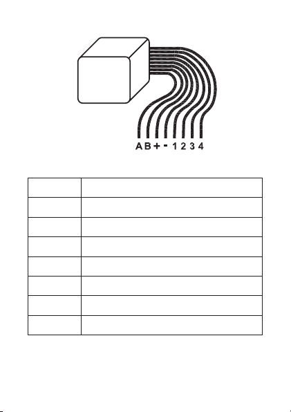
Herausgeführte Adern:
A Bus A
B Bus B
+ Busspannungsversorgung +
- Busspannungsversorgung -
1 Kanal 1
2 Kanal 2
3 Kanal 3
4 Kanal 4
7

4 Allgemeine Systeminformation
zu HomeMatic
Dieses Gerät ist Teil des HomeMatic Haussteuersystems.
Alle Geräte werden mit einer Standardkonfiguration
ausgeliefert. Darüber hinaus ist die Funktion des
Gerätes über ein Programmiergerät und Software
konfigurierbar. Welcher weitergehende Funktionsumfang sich damit ergibt, und welche Zusatzfunktionen sich im HomeMatic System im Zusammenspiel
mit weiteren Komponenten ergeben, entnehmen Sie
bitte der gesonderten Konfigurationsanleitung oder
dem HomeMatic Systemhandbuch.
Alle technischen Dokumente und Updates finden Sie
stets aktuell unter www.HomeMatic.com.
8

5 Allgemeine Hinweise zum
Bussystem
5.1 Allgemeine Hinweise zur Installation
Grundsätzlich kann man die Anschlüsse der HMWKomponenten in zwei Gruppen einteilen. In die
Lastseite und in die Steuerseite (24 V- Spannungs
versorgung, Tastereingänge, RS485-Bus).
Lastseite
Da lastseitig typischerweise 230 V-Netzverbraucher
geschaltet werden, ist hier der Einsatz von VDEgerechten Installationsleitungen, wie beispielsweise
NYM-Leitung etc., erforderlich. Die Leitungsquerschnitte richten sich nach den gängigen VDEVorschriften und betragen für Installationen im
Nennlastbereich der Aktoren 1,5 mm2.
Steuerseite
Auf der Steuerseite hingegen kommt lediglich
ungefährliche Schutzkleinspannung zum Einsatz.
Da innerhalb der Module eine galvanische Trennung
zwischen Last und Steuerseite besteht, brauchen
hier keine netzspannungsfesten Leitungen verwendet zu werden. Es empfiehlt sich die Verwendung
-
9

von Fernmelde-Installationsleitung oder vergleichbarer Steuerleitung. Zu beachten ist allerdings, dass
die Leitungen von Last und Steuerseite innerhalb
der Unterverteilung getrennt entsprechend den VDERichtlinien zu verlegen sind. Dabei ist ein Mindestabstand von 8 mm zwischen beiden Leitungsarten
zu beachten.
Beim Anschluss des RS485-Busses sind die AKlemmen, die B-Klemmen, die 24 V-Spannungsver
sorgung und die Masseklemmen der Module einer
Unterverteilung (max. 127 Stück) jeweils miteinander
zu verbinden. Ein Anschlussschema mit Bus-System finden Sie im Systemhandbuch. Beim Einsatz
mehrerer Module ist ein Busabschluss erforderlich.
Informationen zum Anschluss finden Sie in der
jeweiligen Bedienungsanleitung.
-
5.2 Topologie des Bussystems
Aus Gründen der Übersicht sollten die HMW-Komponenten immer gruppenweise in Unterverteilungen
montiert werden. Wie viele Unterverteilungen angemessen sind, hängt dabei von der Art und Größe
des zu realisierenden Projektes ab und ist individuell
festzulegen.
10

Es ist auf jeden Fall zu empfehlen, auf jeder Etage
mindestens eine Unterverteilung zu installieren. Bei
größeren Gebäuden kann es auch sinnvoll sein,
mehrere Verteilungen pro Etage (z. B. separat für
jeden Flur) vorzusehen. Entsprechend sind alle Lastund Steuerleitungen sternförmig zu den entsprechenden Unterverteilungen zu führen. Die Stromversorgung erfolgt über das Hutschienen-Netzteil
HMW-Sys-PS7-DR oder ein anderes, entsprechend
der Anzahl und Gesamtstromaufnahme aller vorhandenen Module in der jeweiligen Unterverteilung
dimensioniertes 24 V-Netzteil. Wenn eine zentrale
Programmierung und Steuerung über die HomeMatic Zentrale erfolgen soll, sollten die HMW-Busleitungen der einzelnen Unterverteilungen sowie
die vom Steuer-PC bzw. einer Zentrale kommende
Leitung an einem unter räumlichen Gesichtspunkten
günstigen Ort zusammengeführt werden, um eine
Trennung der einzelnen Busabschnitte zu erreichen
und ggf. eine Fehlersuche zu vereinfachen. Üblicherweise ist dies der Raum, in dem die Zentrale des
HomeMatic-Systems installiert wird.
11

6 Installation
Installation mit vier Eingangskanälen
Bei Verwendung der HomeMatic Zentrale können
die Kanäle als Ausgänge umkonfiguriert werden.
12

7 Zuordnung von Tastereingängen
und Aktorkanäle
Im Auslieferungszustand sind alle Kanäle des
Gerätes als Tastereingänge konfiguriert. Sie können
die Eingänge an beliebige am Bus befindliche Aktorkanäle anlernen.
7.1 Anlernen von Tastereingängen an
Aktorkanäle
Bitte lesen Sie diesen Abschnitt erst vollständig, bevor sie mit dem Konfigurieren
beginnen!
Im Auslieferungszustand sind die Tasterein-
gänge keinem Aktorkanal zugeordnet (auch
nicht den Aktorkanälen des Gerätes an dem sie sich
befinden)
Zuordnung von Tastereingängen zu Aktorkanälen
• Drücken Sie die Programmiertaste des zuzu
ordnenden Aktor(kanals) am Modul so lange,
bis dessen Kanal-LED langsam blinkt (nach ca.
3 Sekunden). Das Modul befindet sich nun im
Anlernmodus.
• Betätigen Sie nun einen Taster an dem Taster-
-
13

eingang (am selben oder einem beliebigen
anderen am Bus angeschlossenen Moduls)
dem Sie den Aktor(kanal) zuordnen wollen.
• Der Aktor(kanal) ist nun diesem Schalteingang
zugeordnet, und die Kanal-LED am Aktor erlischt.
• Testen sie die Zuordnung durch Drücken des
zugeordneten Tasters. Der Aktor(kanal) sollte
entsprechend der Konfiguration des Tastereingangs reagieren.
• Wollen Sie den Aktor(kanal) einem weiteren
Tastereingang zuordnen, so wiederholen sie
diesen Vorgang.
Je nach Aktor werden Tastereingänge unterschiedlich angelernt:
Aktor Tastenverhalten
Schaltaktor,
Dimmaktor
Jalousieaktor
14
Angelernte Tasten verhalten
sich wie Toggle-Taster
Je nachdem ob der Anlernmodus am Aktor mit der
▲- oder ▼- Taste ausgelöst
wurde wird die anzulernende
Taste als „Öffnen“ oder
„Schließen“ angelern, nicht
als Toggle-Taste.

Wird eine an einen Aktor angelernte Taste
erneut an denselben Aktor angelernt, wird die
alte Zuordnung überschrieben.
7.2 Aufheben der Zuordnung von Tastereingängen zu Aktorkanälen
Aufheben der Zuordnung von Tastereingang und
Aktor(kanal)
• Drücken Sie die Programmiertaste des
Aktor(kanals), dessen Zuordnung Sie aufheben
möchten so lange, bis dessen Kanal-LED vom
langsamen in das schnelle Blinken übergeht
(nach ca. 6 Sekunden).
• Lassen Sie die Taste los. Das Schaltmodul
befindet sich nun im Löschmodus.
• Drücken sie nun einen Taster am Tastereingang
eines Moduls, dessen Zuordnung Sie aufheben
wollen. Die Kanal-LED am Aktor erlischt und
die Zuordnung ist aufgehoben, der Aktor(kanal)
wird von diesem Schalteingang nicht mehr
geschaltet.
• Überprüfen Sie die Einstellung durch Betätigen
eines Tasters am gelöschten Tastereingang,
der Aktor(kanal) darf nicht mehr reagieren.
15

Alle Anlernvorgänge können Sie durch kurzes
Betätigen der Programmiertaste abbrechen.
8 Wartung und Reinigung
Das Produkt ist wartungsfrei. Überlassen Sie eine
Reparatur einer Fachkraft.
9 Technische Daten
Kommunikation: RS485-Bus
Spannungsversorgung: 24 V / DC
Stromaufnahme: 10 mA
Max. Ausgangsstrom: 15 mA
Gehäuseabmessungen: 24 x 27 x 20 mm
Gewicht: 30 g
Länge der Anschlussleitungen: 125 mm
16
(H x B x T) (ohne
Anschlußleitungen)

Entsorgungshinweis:
Gerät nicht im Hausmüll entsorgen! Elektronische Geräte sind entsprechend der Richt-
linie über Elektro- und Elektronik-Altgeräte
über die örtlichen Sammelstellen für Elektronik-Altgeräte zu entsorgen.
Das CE-Zeichen ist ein Freiverkehrszeichen,
das sich ausschließlich an die Behörden
wendet und keine Zusicherung von Eigenschaften
beinhaltet.
17

Table of Contents
1 Information concerning these instructions . 19
2 Hazard information
3 Function
4
5
5.1
5.2 Topology of the bus system
6 Installation
7 Assignment of button inputs and actuator
7.1 Teaching button inputs to actuator
7.2 Clearing the assignment of button inputs to
8 Maintenance and cleaning
9 Technical specifications
18
. . . . . . . . . . . . . . . . . . . . . . . . . . . . . 20
General system information
General
information on the bus system . . . . 23
General
information on the installation . . . . 23
channels . . . . . . . . . . . . . . . . . . . . . . . . . . . . 27
channels . . . . . . . . . . . . . . . . . . . . . . . . . . . . 27
actuator channels . . . . . . . . . . . . . . . . . . . . . 29
. . . . . . . . . . . . . . . . . . . . 19
on HomeMatic . 22
. . . . . . . . . . . . . 24
. . . . . . . . . . . . . . . . . . . . . . . . . . . 26
. . . . . . . . . . . . . . 30
. . . . . . . . . . . . . . . . 30

1 Information concerning these
instructions
Read these instructions carefully before beginning
operation with your HomeMatic components.
Keep the instructions handy for later consultation!
Please hand-over the operating manual as well
when you hand-over the device to other persons
for use.
Symbols used:
Attention! This indicates a hazard.
Note. This section contains additional important information!
2 Hazard information
This device is to be operated indoors only
and keep away from the influences of
humidity, dust and sunshine or other radiating heat
sources.
19

3 Function
• 4 connections, optionally as inputs or outputs
(via the HomeMatic Center)
• Channels configured as inputs can be configured as desired and optional actuator channels can be assigned (from other modules as
well).
• As many potential-free buttons as are neces
sary can be connected to one input.
•
Non-volatile memory for configuration data.
20
-

Wires used:
A Bus A
B Bus B
+ Bus power supply +
- Bus power supply -
1 Channel 1
2 Channel 2
3 Channel 3
4 Channel 4
21

4 General system information
on HomeMatic
This device is a component of the HomeMatic Home
Control System.
All devices are delivered in a standard configuration.
The functionality of the device can also be configured with a programming device and software.
Further resulting functionality and the additional
functions provided in the HomeMatic system
combined with other components are described in
the separate Configuration Instructions and in the
HomeMatic System Manual.
All current technical documents and updates are
provided under www.HomeMatic.com.
22

5 General information on
Bus system
5.1 General information on the installation
Basically, the connections of the HMW components
can be divided into two groups. In the load side and
in the control side (24 V power supply, button inputs,
RS485 Bus).
Load side
Since normally a 230 V consumer is on the load
side, using VDE-conforming installation wires, such
as e.g. NYM wiring, etc. is required. The wire crosssection conform with the standard VDE regulations
and is 1.5 mm2 for installations in the nominal load
range of actuators.
Control side
On the control side however, only non-hazardous
safety extra-low voltages are used. Since there is
electrical isolation between the load and control
sides in the module, no mains power capable wires
have to be used. Using interior telecommunications
wiring or comparable control wiring is recommended. Make sure however, that the wires of the load
23

and the control side are separated conforming with
VDE regulations within the sub-distribution. Keep a
minimum spacing of 8 mm between the two types
of wiring.
When connecting the RS485 bus, the A terminals,
the B terminals, the 24 V power supply and the
ground terminal of the modules of a sub-distribution
(max. 127 segments) are to be connected with one
another. A connection diagram with bus system is
provided in the system manual. When using several
modules, a bus termination is required.
Information on the connections is provided in the
respective operating instructions.
5.2 Topology of the bus system
The HMW components should always be mounted
in groups of sub-divisions to provide a better overview. The number of sub-divisions that is appropriate depends on the type and size of the project and
is to be defined accordingly.
Installing at least one sub-division on each level is
recommended. Larger buildings may require plan-
24

ning several sub-divisions per level (e.g. separate for
every floor). All load and control wiring should also
be run in a star format to the respective sub-divisions. The power supply is done through a DIN rail
power supply HMW-Sys-PS7-DR or another
24 V power supply dimensioned according to the
number and total current consumption of all existing
modules in the respective sub-division. If central
programming and control is to be done through
the HomeMatic Centre, the HMW bus lines for the
individual sub-divisions and the lines coming from
the control PC or a Centre should be run together
in a room according to available space in order
to achieve a separation of the individual bus segments and to simplify troubleshooting if necessary.
Normally, this is the room in which the HomeMatic
system Centre is installed.
25
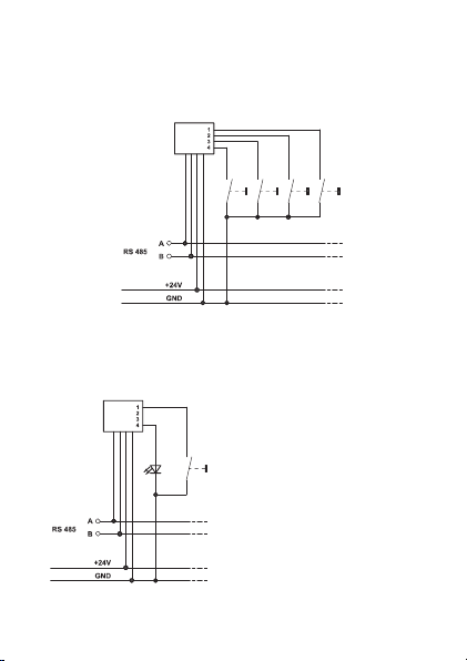
6 Installation
Installation with four input channels
The channels can be reconfigured as outputs when
using the HomeMatic Center.
26

7 Assignment of button inputs
and actuator channels
All channels of the device are configured as button
inputs in delivery status. You can teach the inputs
for any actuator channels on the bus.
7.1 Teaching button inputs to actuator
channels
Please read this section completely before
starting with any configuring!
The button inputs are not assigned to any
actuator channels in factory status (not the
actuator channels of the device on which they are
located either)
Assignment of button inputs to actuator channels
• Press the programming button of the actuator
(channel) to be assigned on the module until
the channel LED flashes slowly (after approx.
3 seconds). The module is now in teach mode.
• Now, actuate a button on the button input (on
the same module or any other module on the
27

bus) that you want to assign to the actuator
(channel).
• The actuator (channel) is now assigned with this
switch input and the channel LED goes dark on
the actuator.
• Test the assignment by pressing the respective
button. The actuator (channel) should react
according to the configuration of the button
input.
• If you want to assign another button input to
the actuator (channel), repeat this procedure.
Depending on the actuator, button inputs are taught
differently:
Actuator Button behavior
Switch actuator,
Dimming actuator
Blind actuator
28
Taught buttons behave like
toggle switches
Depending on whether teach
mode on the actuator was
triggered with the ▲- or
▼- button, the button to be
taught is taught as "Open"
or "Close", not as a toggle
button.

If a button that was taught for an actuator is
taught for the same actuator again, the old
assignment is overwritten.
7.2 Clearing the assignment of button
inputs to actuator channels
Clearing the assignment of a button input and
actuator (channel)
• Press the programming button of the actuator
(channel) that you want to clear the assignment
for until the respective channel LED switches
from slow flashing to quickly flashing (after
approx. 6 seconds).
• Release the button. The module is now in
delete mode.
• Now, press a button on the button input of
a module for which you want to clear the
assignment. The channel LED on the actuator
goes dark and the assignment is deleted, the
actuator (channel) is no longer actuated on this
switch input.
• Test the setting by actuating a button on the
deleted button input, the actuator (channel)
should not react.
29

All teach procedures can be aborted by
briefly actuating the programming button.
8 Maintenance and cleaning
This product is maintenance-free. Repairs are only
to be done by trained professionals.
9 Technical specifications
Communication: RS485-Bus
Voltage supply: 24 V / DC
Current consumption: 10 mA
Max. output current: 15 mA
Housing dimensions: 24 x 27 x 20 mm
Weight: 30 g
Length of the connecting lines: 125 mm
30
(H x W x D) (without connecting
lines)

Instructions for disposal:
Do not dispose off the device as part of
household garbage! Electronic devices are
to be disposed of in accordance with the
guidelines concerning electrical and electronic devices via the local collecting point for old electronic
devices.
The CE sign is a free trade sign addressed
exclusively to the authorities and does not
include any warranty of any properties.
31

eQ-3 AG
Maiburger Straße 29
D-26789 Leer
www.eQ-3.com
32
 Loading...