


Montage- und
Bedienungsanleitung (S. 2)
Mounting instruction and
operating manual (p. 33)
WinMatic
Funk-Fensterantrieb:
WinMatic
Radio-controlled window drive:
HM-Sec-Win

2
2. Ausgabe Deutsch 10/2008
Dokumentation © 2007 eQ-3 Ltd., Hong Kong
Alle Rechte vorbehalten. Ohne schriftliche Zustimmung des Herausgebers darf
dieses Handbuch auch nicht auszugsweise in irgendeiner Form reproduziert werden
oder unter Verwendung elektronischer, mechanischer oder chemischer Verfahren
vervielfältigt oder verarbeitet werden.
Es ist möglich, dass das vorliegende Handbuch noch drucktechnische Mängel oder
Druckfehler aufweist. Die Angaben in diesem Handbuch werden jedoch regelmäßig
überprüft und Korrekturen in der nächsten Ausgabe vorgenommen. Für Fehler technischer oder drucktechnischer Art und ihre Folgen übernehmen wir keine Haftung.
Alle Warenzeichen und Schutzrechte werden anerkannt.
Printed in Hong Kong
Änderungen im Sinne des technischen Fortschritts können ohne Vorankündigung
vorgenommen werden.
73472 / V 1.1

3
Inhaltsverzeichnis
1 Hinweise zu dieser Anleitung ......................................5
2 Gefahrenhinweise ...............................................5
3 Funktion .......................................................6
3.1 Kurzer Überblick ................................................6
3.2 Lieferumfang ...................................................9
4 Allgemeine Systeminformation zu HomeMatic.........................9
5 Allgemeine Hinweise zum Funkbetrieb...............................9
6 Montage ......................................................10
6.1 Übersicht ..................................................... 10
6.2 Durchführung der Montage ....................................... 10
6.2.1 Maximale Kippweite messen...................................... 10
6.2.2 WinMatic auf geeignete Montageseite vorbereiten ....................11
6.2.3 Fenstergriff abmontieren ......................................... 12
6.2.4 Montageposition für den Zahnstangenhalter vorbereiten . . . . . . . . . . . . . . . 13
6.2.5 Montage Halteplatte ............................................14
6.2.6 Montage Zahnstangenhalter ......................................15
6.2.7 Montage Zahnstange und Akkupack ...............................17
7 Inbetriebnahme ................................................ 18
7.1 Anpassung des Fensterantriebs an das verwendete Fenster ............18
7.1.1 Montageseite des Fensterdrehgriffs einstellen .......................19
7.1.2 Heranziehkraft des Kippantriebes.................................. 20
7.1.3 Maximale Kippweite.............................................21
7.2 Anlernen von Fernbedienungen und Tastern in zwei Schritten ...........22
7.2.1 Übersicht ..................................................... 22
7.2.2 Anlernen 1. Schritt – (reines) Anlernen (ohne Parameter) ...............23
7.2.3 Anlernen 2. Schritt – Einstellen der Parameter........................24
7.3 Ablernen von Fernbedienungen ................................... 25
8 Bedienung ....................................................25
8.1 Bedienung am Gerät ............................................25
8.2 Vollständiges Öffnen des Fensters .................................26
8.3 Bedienung über angelernte Bedienelemente ......................... 26
8.3.1 Schliessen und Kippen .......................................... 26
8.3.2 Erhöhen der Fahrgeschwindigkeit während der Ausführung einer
Fahrbewegung .................................................26
8.4 Informationen im Gerätedisplay ................................... 27

4
8.4.1 Anzeige der zuletzt benutzten Bedieneinheit ......................... 27
8.4.2 Anzeige beim Ausführen von Profilen...............................27
8.5 Notbetrieb.....................................................27
8.6 Übersicht über das Verhalten der WinMatic und angelernten Bedienelementen in Abhängigkeit vom Modus und von den gedrückten Tasten
am Bedienelement. Verhalten eines noch nicht angelernten Senders:.....28
9 Meldungen und Fehlermeldungen .................................30
9.1 Leerer Akku ...................................................30
9.2 Mechanischer Fehler ............................................30
10 Zurücksetzen in den Auslieferungszustand .......................... 30
11 Der WinMatic Akkupack .........................................31
12 Wartung und Reinigung..........................................31
13 Technische Daten...............................................32
5
1 Hinweise zu dieser Anleitung
Lesen Sie diese Anleitung sorgfältig, bevor Sie ihre HomeMatic Komponenten in
Betrieb nehmen.
Bewahren Sie die Anleitung zum späteren Nachschlagen auf!
Wenn Sie das Gerät anderen Personen zur Nutzung überlassen, übergeben Sie auch
diese Bedienungsanleitung.
Benutzte Symbole:
Achtung! Hier wird auf eine Gefahr hingewiesen.
Hinweis. Dieser Abschnitt enthält zusätzliche wichtige Informationen!
2 Gefahrenhinweise
WinMatic ist ein technisches System, das durch verschiedene Ursachen
ausfallen kann. Deshalb sollten Sie bei der Nutzung des Gerätes folgende
Hinweise beachten:
Setzen Sie die WinMatic nicht an Fernstern und Türen ein, die als Fluchtwege dienen.
Achtung! Wichtige Anweisung für sichere Montage:
Prüfen Sie vor dem Anbau des Fensterantriebes ob dieser sich in einwandfreiem Zustand befindet. Prüfen Sie sämtliches mitgeliefertes Montagematerial auf Vollständigkeit und intakten Zustand.
Stellen Sie sicher, dass ein Einschließen von Fremdkörpern zwischen Fensterflügel
und Fensterrahmen nicht möglich ist.
Prüfen Sie nach der Montage die ordnungsgemäße Funktion der WinMatic.
Die WinMatic ist nicht für Rundbogen-, Stichbogen- oder Schrägfenster
geeignet!
Sonstige Hinweise:
Da es bei der Montage zu Beschädigungen des Fensterflügels durch Verwendung
von Befestigungsschrauben kommen kann, besteht bei Mietwohnungen die Gefahr
dass es zu einer Schadensersatzforderung oder zum Einbehalt der Mietkaution
kommt.
Die eQ-3 AG haftet im Rahmen der Produkthaftung für das WinMatic-System selbst,
nicht für Folgeschäden bei seinem Betrieb, z. B. die Beschädigung eines Fensters,
etc..

6
Achtung! Hinweise zum sicheren Betrieb!
Während der Bewegung, insbesondere der automatischen Schließbewe-
gung des Fensterflügels, nicht die Hände zwischen Rahmen und bewegten
Flügel bringen.
Kleine Kinder dürfen die WinMatic nicht unbeaufsichtigt bedienen! Bei Benutzung
der WinMatic insbesondere bei Einbindung in übergreifende automatische Steuerungen dürfen Kinder und Haustiere nicht unbeaufsichtigt bleiben (Einklemmgefahr!)!
Betreiben Sie das Gerät nur in Innenräumen und vermeiden Sie den Einfluss von
Feuchtigkeit, Staub sowie Sonnen- oder andere Wärmebestrahlung.
WinMatic Akkupack:
Akkupack nicht ins Feuer werfen!
Vorsicht! Explosionsgefahr bei unsachgemäßem Austausch der Batterie.
Batterieanschlussklemmen niemals kurzschließen!
Laden Sie den Akkupack nur mit dem zur WinMatic gehörigen Steckernetzteil!
3 Funktion
3.1 Kurzer Überblick
Die WinMatic kommt zum Einsatz an herkömmlichen Fassadenfenstern, die ausgeführt sind als Kipp- oder Drehkippfenster. Dabei wird der Fenstergriff durch die
WinMatic ersetzt, die anstelle des Fenstergriffes die Fensterbeschläge mit ihren
Verriegelungspunkten antreibt. Über eine gebogene Zahnstange, die mit dem Fensterrahmen verbunden ist, führt die WinMatic die Kipp-Bewegung des Fensterflügels
aus.
Die WinMatic ist nicht für Rundbogen-, Stichbogen- oder Schrägfenster
geeignet!
Das Ver- und Entriegeln sowie das Kippen erfolgt von innen und außen drahtlos über
Funk (868,3 MHz).
Von innen können Sie den Antrieb über am Antrieb befindliche Tasten bedienen.
Durch Ausklinken der Zahnstange und Drehen am Handrad ist eine manuelle Bedienung möglich.
Sowohl Handsender als auch Fensterantrieb arbeiten batteriebetrieben, sind also
nicht abhängig vom Vorhandensein eines Netzanschlusses in Fensternähe.
Der Fensterantrieb verfügt über ein LC-Kontrolldisplay, über das sowohl die Programmierung erfolgt als auch Statusmeldungen im normalen Betrieb angezeigt
werden. Der Bediener kennt damit stets den Gerätestatus.
Um eine hohe Verfügbarkeit des Systems zu erhalten, erfolgen Warnungen über
7
einen fast erschöpfte Akkupack rechtzeitig über deutliche Anzeigen.
Eine eindeutige Anzeigesymbolik und Klarschrift-Anzeige gewährleistet einen
schnellen Überblick über alle Zustände bei Konfiguration und Betrieb.
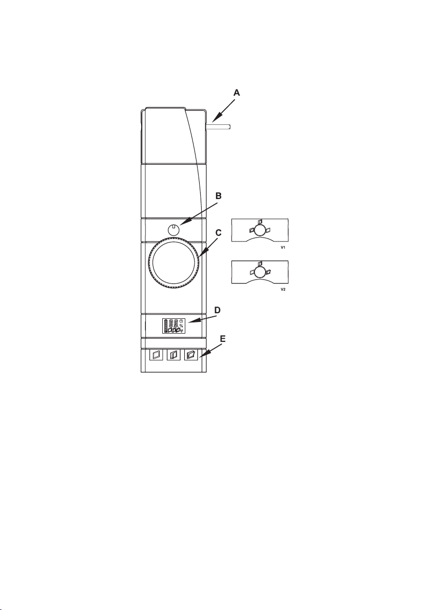
WinMatic:
A – Antriebsstange
B – Positionsanzeiger für Fensterdrehgriff
C – Handrad
D – Gerätedisplay
E – Bedientasten
V1/V2 – Blenden Positionsanzeiger für Fensterdrehgriff

8
WinMatic (Ansicht von unten):
A – Buchse für Akkupack
B – Handrad
C – Antriebsstange
WinMatic Akkupack:
A – Anschluss für Steckernetzteil
B – Steckverbinder zum Anschluss an die WinMatic
C – Geräte-LED

9
3.2 Lieferumfang
• Funk-Fensterantrieb
• Montageplatte
• 2SchraubenM5x35mm
• 4selbstschneidendeSchrauben(3,5x20mm)
• ZahnstangemitBefestigungsmaterial
• DreiGriffachsenunterschiedlicherLänge
• BlendenPositionsanzeigerfürFensterdrehgriff
• WinMaticAkkupack
• Steckernetzteil
• Bedienungsanleitung
4 Allgemeine Systeminformation zu HomeMatic
Dieses Gerät ist Teil des HomeMatic Haussteuersystems und arbeitet mit dem bidirektionalen BidCoS® Funkprotokoll.
Alle Geräte werden mit einer Standardkonfiguration ausgeliefert. Darüber hinaus ist
die Funktion des Gerätes über ein Programmiergerät und Software konfigurierbar.
Welcher weitergehende Funktionsumfang sich damit ergibt, und welche Zusatzfunktionen sich im HomeMatic System im Zusammenspiel mit weiteren Komponenten
ergeben, entnehmen Sie bitte der gesonderten Konfigurationsanleitung oder dem
HomeMatic Systemhandbuch.
Alle technischen Dokumente und Updates finden Sie stets aktuell unter www.HomeMatic.com.
5 Allgemeine Hinweise zum Funkbetrieb
Die Funk-Übertragung wird auf einem nicht exklusiven Übertragungsweg realisiert
weshalb Störungen nicht ausgeschlossen werden können.
Weitere Störeinflüsse können hervorgerufen werden durch Schaltvorgänge, Elektromotoren oder defekte Elektrogeräte.
Die Reichweite in Gebäuden kann stark von der im Freifeld abweichen.
Außer der Sendeleistung und den Empfangseigenschaften der Empfänger
spielen Umwelteinflüsse wie Luftfeuchtigkeit neben baulichen Gegebenheiten vor Ort eine wichtige Rolle.
Hiermit erklärt die eQ-3 Entwicklung GmbH, dass sich dieses Gerät in Übereinstimmung mit den grundlegenden Anforderungen und den anderen relevanten Vorschriften der Richtlinie 1999/5/EG befindet.
Die vollständige Konformitätserklärung finden Sie unter www.HomeMatic.com.
10
6 Montage
6.1 Übersicht
Bitte lesen Sie diesen Abschnitt erst vollständig, bevor sie mit der Montage beginnen!
Prüfen Sie vor der Montage unbedingt, ob das Fenster korrekt justiert ist und
ob die Fensterbeschläge leichtgängig sind und korrekt schliessen. Lassen
Sie gegebenenfalls die Fenster von einem Fachmann neu justieren. Die Montageposition der WinMatic am Fenster ist nachträglich nicht mehr veränderbar!
Die Montage verläuft in mehreren Schritten.
Es wird zunächst der komplette Montageprozess beschrieben! Zum Anpassen der
Parameter der WinMatic an das verwendete Fenster müssen Zahnstange und Griffachse wieder demontiert werden.
• MaximaleKippweitedesFenstersmessen(diesebenötigenSieumdiemaximale Kippweite so einzustellen, dass Sie die Zahnstange noch ausklinken
können.)
• WinMaticfürdiegeeigneteMontageseitevorbereiten(u.U.nichtnötig)
• FenstergriffvomFensterabmontieren
• MontageZahnstangenhaltervorbereiten
• HalteplattederWinMaticmontieren
• Zahnstangenhaltermontieren
Nachfolgend kann die Inbetriebnahme, die im nächsten Kapitel beschrieben ist erfolgen.
6.2 Durchführung der Montage
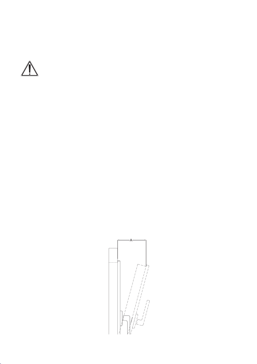
6.2.1 Maximale Kippweite messen
Bringen Sie das Fenster in Kippstellung.
Messen Sie die maximale Kippweite (A), indem Sie den entstehenden Spalt zwischen Fensterflügel und Rahmen mit einem Zentimetermessstab messen.

11
6.2.2 WinMatic auf geeignete Montageseite vorbereiten
Bereiten Sie die WinMatic gegebenenfalls für die geeignete Montageseite vor. Im
Auslieferungszustand ist die WinMatic zur Montage an Fenstern mit Rechtsanschlag.
Zum Umbau auf linksangeschlagene Fenster (Fenstergriff rechts) gehen Sie wie
nachfolgend beschrieben vor.
Dazu entfernen Sie die Schraube der Wellensperre (A) und nehmen die Wellensperre
aus dem Gerät.
Schieben Sie die Welle (C) in Pfeilrichtung bis zum Anschlag. Der Stopper der Welle
(B) befindet sich nun auf der anderen Seite der Wellensperre. Setzen Sie die Wellensperre wieder ein und fixieren Sie sie wieder mit der zugehörigen Schraube.
12
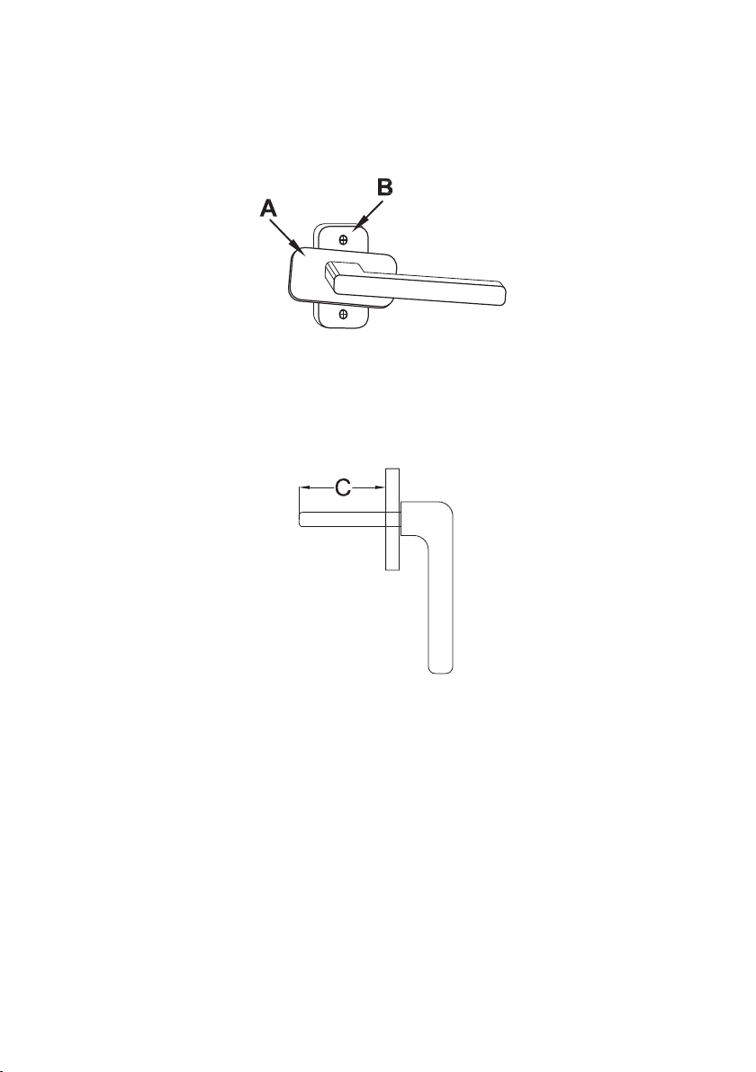
6.2.3 Fenstergriff abmontieren
Bringen Sie den Fenstergriff in Stellung „Öffnen“ (waagerecht).
Drehen Sie die Abdeckung (A) des Griffs zur Seite um an die
Befestigungsschrauben (B) zu gelangen.
Lösen Sie die Schrauben und nehmen Sie sie heraus.
Messen Sie nun die Länge der Griffachse (C) des Fenstergriffes um die
passende der mitgelieferten Griffachsen zur WinMatic auszuwählen.
13
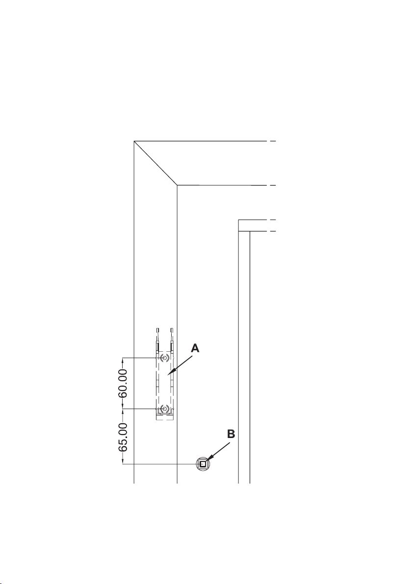
6.2.4 Montageposition für den Zahnstangenhalter vorbereiten
Reinigen Sie den Fensterrahmen im Bereich neben dem Griff (damit bei Klebemontage des Zahnstangenhalters dieser auch sicher haftet).
Markieren Sie die Montageposition (Höhe) des Zahnstangenhalters gemäß der nachfolgenden Zeichnung. Eine genaue Positionsbestimmung erfolgt nach Montage der
WinMatic.
14
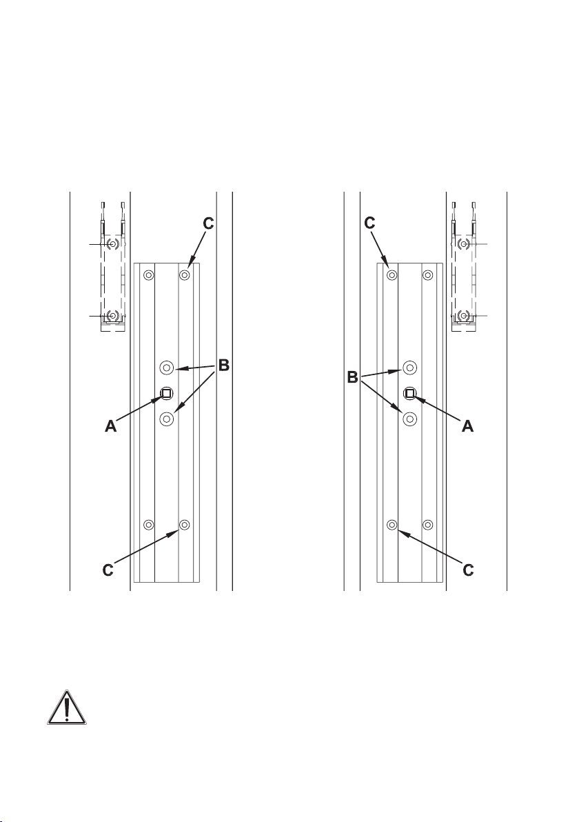
6.2.5 Montage Halteplatte
Befestigen Sie die Halteplatte mit den mitgelieferten Schrauben (M5 x 35 mm) bei.
Beachten Sie die parallele Ausrichtung der Montageplatte zum Rahmen. Orientieren
Sie die Platte gemäß der Zeichnung mit dem längeren Stück unterhalb des Durchlasses für den Fensterdrehgriff. Benutzen Sie dazu die Bohrungen die zur Befestigung des Fenstergriffes dienen (B).
Bei Bedarf können Sie die Halteplatte zusätzlich mit den mitgelieferten selbstschneidenden Schrauben ( 3,5 x 20 mm) befestigen. Benutzen Sie dabei nur die Löcher auf
der zum Fensterglas weisenden Seite (jeweils C in den Zeichnungen).
Die Verwendung selbstschneidender Schrauben zur Befestigung führt zu
Beschädigungen am Fensterflügel. Bei Mietwohnungen könnte dies zu einer
Schadensersatzforderung oder zum Einbehalt der Mietkaution führen.

15
6.2.6 Montage Zahnstangenhalter
Schieben Sie die Winmatic von oben in Pfeilrichtung (1) auf die Montageplatte.
Überprüfen Sie die auf dem Fensterrahmen markierte Position des Zahnstangenhalters. Stecken Sie dabei das Ritzel noch nicht auf. Gegebenenfalls nehmen Sie noch
kleine Korrekturen der Montageposition vor.
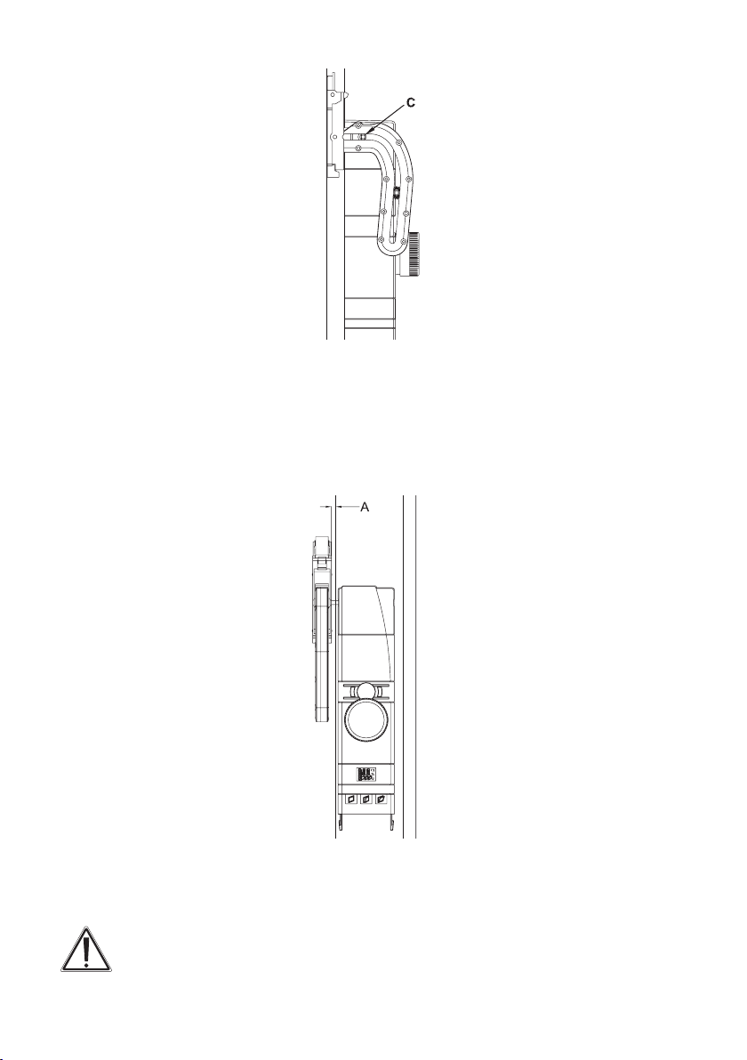
16
Justieren Sie die Montagehöhe des Halters so, dass das erste Stück Fahrweg in der
Zahnstange bei geschlossenem Fenster waagerecht verläuft.
Beachten Sie bei der Montage des Halters ebenfalls den seitlichen Abstand (A) zum
Fensterflügel, damit dieser sich noch frei bewegen kann. Wählen Sie den Abstand
nicht zu groß, damit die Welle ausreichend weit ins Ritzel fassen kann.
Gegebenenfalls markieren Sie nun eine optimierte Montageposition der Zahnstangenhalterung.
Rasten Sie die Zahnstange aus dem Halter aus und befestigen Sie den Halter mit
Klebestreifen oder mit den beiliegenden selbstschneidenden Schrauben.
Die Verwendung selbstschneidender Schrauben zur Befestigung führt zu
Beschädigungen am Fensterflügel. Bei Mietwohnungen könnte dies zu einer
Schadensersatzforderung oder zum Einbehalt der Mietkaution führen.
17
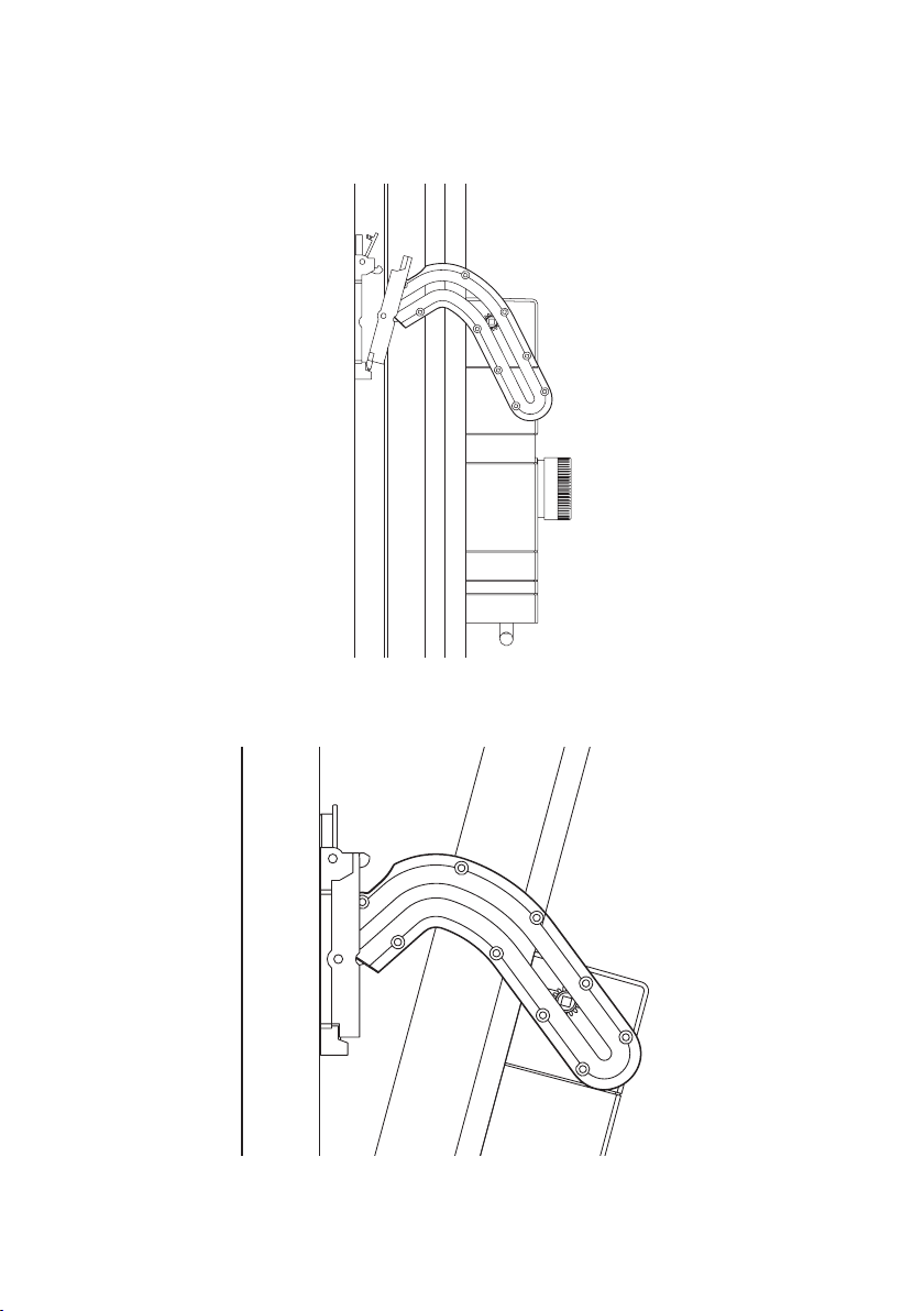
6.2.7 Montage Zahnstange und Akkupack
Stecken Sie die Zahnstange mit Ritzel auf die Welle auf.
Fixieren Sie die Zahnstange im Halter und rasten sie ein.
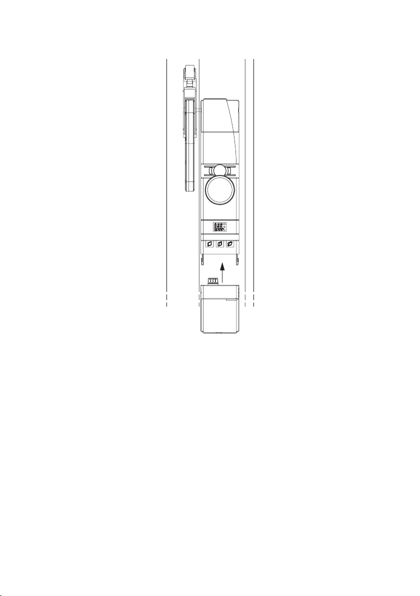
18
Stecken Sie den Akku von unten auf die WinMatic auf.
7 Inbetriebnahme
7.1 Anpassung des Fensterantriebs an das verwendete Fenster
Bitte lesen Sie diesen Abschnitt erst vollständig, bevor sie mit den Einstellungen
beginnen!
Der Setupmodus dient zur Einstellung der Parameter die durch die Eigenschaften
des Fensters festgelegt sind:
• MontagederWinMaticlinksoderrechts
• Heranziehkraft
• maximaleKippweite
Der Setupprozess läuft schrittweise ab.
Drücken Sie die Taste „Schließen“ und die Taste „Öffnen“ gemeinsam für länger
als 4 Sekunden um in den Setupmodus zu gelangen (genauso können Sie ihn auch
wieder abbrechen).
Ist noch keine Masterfernbedienung angelernt, erreichen Sie den Setupmodus
direkt.
19
Wurde hingegen bereits eine Masterfernbedienung angelernt, erscheint im Display
zunächst „X“. Drücken Sie innerhalb von 3 Minuten eine Taste der Masterfernbedienung, gelangen Sie in den Setupmodus ansonsten wird abgebrochen. Erfolgt
innerhalb des Setupmodus 3 Minuten keine Aktion wird der Setupmodus beendet.
Im Setupmodus sind die drei Tasten wie folgt belegt:
Taste „Schließen“: „-“
Taste „Öffnen“: „+“
Taste „Kippen“ ( länger als 4 Sekunden gedrückt): Eingabe bestätigen und weiter
Nach dem letzten Schritt führt das Bestätigen der letzten Eingabe zum Beenden des
Setupmodus. Erfolgt 3 Minuten lang keine Eingabe wird der Setupmodus automatisch verlassen.
Während des Setupmodus ist keine Bedienung möglich.
Bei Auftreten eines Fehlers oder bei einer Fehlbedienung wird der
Setupmodus abgebrochen.
7.1.1 Montageseite des Fensterdrehgriffs einstellen
Wenn Sie den Setupmodus starten muss das Fenster geöffnet sein, die Griffachse muss demontiert und die Zahnstange ausgeklinkt sein!
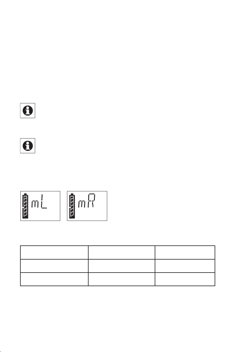
Im Display wird die Griff- bzw. Montageseite durch „mR“ für rechts montiert bzw.
„mL“ für links montiert angezeigt. Wählen Sie die Montageseite durch + (rechts) und
– (links) aus.
Während der Einstellungen ist der Motor des Kippantriebes aktiv.
Bestätigen Sie die Eingabe durch langes Drücken der Taste „Kippen“
(> 4 Sekunden).
Anschlagseite
links
rechts
Nach einiger Zeit (Countdown im Display mit Symbol „Uhr“) stoppt der Kippantrieb
und die WinMatic bringt die Griffachse in Stellung „Fenster Öffnen“. Dabei blinkt das
Symbol „geöffnetes Fenster“.
Das Ende dieses Vorgangs ist daran zu erkennen, dass das Symbol „geöffnetes Fenster“ dauerhaft angezeigt wird und zusätzlich das Symbol „gekipptes Fenster“ blinkt.
Griffposition /
Montageseite WinMatic
rechts mR
links mL
Einstellung
20
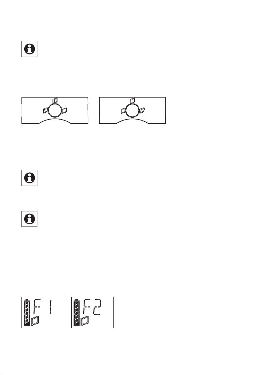
Stecken Sie nun die Griffachse mit Indikator nach oben ein.
Die WinMatic wird mit drei Griffachsen unterschiedlicher Länge geliefert.
Wählen Sie zur Montage die längstmögliche Achse aus, die sich noch
montieren lässt. Orientieren Sie sich bei der Auswahl an der Länge der
Achse des demontierten Fenstergriffs. Zum Einschieben der als passend erkannten
Griffachse kann auch eine etwas erhöhte Kraft notwendig sein.
Montieren Sie nun die passende Blende mit Positionsanzeiger für den Fenstergriff.
Abbildung: Blende für links montierte und für rechtsmontierte WinMatic
Drücken Sie das Fenster zu. Bringen Sie nun das Fenster in Stellung „Kippen“. Dazu
stellen Sie den Drehantrieb mit dem Handrad (Herunterdrücken und Drehen) so ein,
dass das Symbol „gekipptes Fenster“ dauerhaft im Display angezeigt wird.
Prüfen Sie, ob das Fenster tatsächlich auf Stellung „Kippen“ steht! Befindet
sich das Fenster noch in Stellung „Geöffnet“ ist die verwendete Griffachse
zu kurz.
Anschließend bringen Sie die Zahnstange an und klinken sie ein.
Beachten Sie vor dem Bestätigen mit Taste „Kippen“ (langer Tastendruck),
dass das Symbol „gekipptes Fenster“ immer noch im Display angezeigt
wird.
7.1.2 Heranziehkraft des Kippantriebes
Die WinMatic zieht den Fensterflügel zunächst mit der kleinsten einstellbaren Kraft
heran. Sie können die Heranziehkraft mit den +/- Tasten erhöhen oder eniedrigen.
Jede neue Einstellung können Sie mit einem kurzen Tastendruck auf Taste 3 prüfen
und gegebenenfalls die Heranziehkraft erhöhen/erniedrigen. Dazu gibt es 6 Stufen,
die im Display symbolisiert werden.
Bestätigen Sie Ihre Einstellung mit einem langen Tastendruck auf Taste „Kippen“
(> 4 Sekunden).

21
Die Heranziehkraft kann zunächst auf dem Wert 1 belassen werden. Sollte
es bei schweren Fensterflügeln oder wenn Wind auf dem Fenster steht nötig
sein, können Sie die Kraft schrittweise erhöhen. Die Kraft muss so groß
sein, dass der Fensterflügel komplett geschlossen ist und das Verschließen mühelos
möglich ist. Dazu rufen Sie einfach erneut den Setupmodus auf.
Bei Verwendung von Doppelklebeband zur Befestigung des Halters für die
Zahnstange lassen Sie die Heranziehkraft auf dem Wert 1! Ansonsten wird
die Klebeverbindung beschädigt.
7.1.3 Maximale Kippweite
Sie können den maximale Kippwinkel mit den +/- Tasten erhöhen oder erniedrigen.
Jede neue Einstellung können Sie mit einem kurzen Tastendruck auf Taste „Kippen“
prüfen und gegebenenfalls verändern. Es gibt 29 Stufen, die im Display symbolisiert
werden.
Als maximale Kippweite (A) sollte nicht der gemessene maximal mögliche
eingestellt werden, sondern ein etwas geringerer, so dass die Zahnstange
noch bequem ausgeklinkt werden kann.
Bestätigen Sie Ihre Einstellung mit einem langen Tastendruck auf Taste „Kippen“
(> 4 Sekunden). Der Setupmodus wird daraufhin verlassen

22
7.2 Anlernen von Fernbedienungen und Tastern in zwei Schritten
7.2.1 Übersicht
Bitte lesen Sie diesen Abschnitt erst vollständig, bevor sie mit dem Anlernen beginnen!
Anlernen:
Falls die WinMatic bereits an eine HomeMatic Zentrale angelernt wurde,
direktes Anlernen am Gerät nicht mehr möglich. In diesem Fall erscheint
beim Aufruf des Anlernmodus im Display kurz „Xc“ und es wird abgebro-
chen. Zusätzliche Anlernvorgänge müssen in diesem Fall über die Zentrale erfolgen.
Weitere Informationen hierzu entnehmen Sie der Dokumentation zur HomeMatic
Zentrale und dem HomeMatic Systemhandbuch.
Nachfolgend ist der Anlernvorgang ohne Zentrale beschrieben!
Als sicherheitsrelevante Komponente wird beim Betrieb der WinMatic eine
Fernbedienung als sogenannte „Master“-Fernbedienung ausgezeichnet –
dies ist automatisch die erste angelernte Fernbedienung. Zum Authentifizieren aller
weiteren Anlernvorgänge muss jetzt immer eine Taste der Masterfernbedienung
betätigt werden.
Geben Sie die „Master“-Fernbedienung nicht weiter, und verwenden Sie sie
nicht zum täglichen Gebrauch. Bei Verlust der Masterfernbedienung kann
nur ein Zurücksetzen in den Auslieferungszustand das Anlernen einer neuen
Fernbedienung als Masterfernbedienung ermöglichen.
Das Anlernen teilt sich in zwei Schritte auf:
• Anlernmodus:AnlernenderFernbedienungmitStandardwerten(Auf/Zu)
• Kongurationsmodus:EinstellenderParameter(wahlweise)
Der Konfigurationsmodus wird nicht automatisch nach dem Anlernen aufgerufen, sondern muss explizit angewählt werden.
• AufrufAnlernmodus:LangerTastendruckaufTaste„Schließen“
(> 4 Sekunden)
• AufrufKongurationsmodus:LangerTastendruckaufTaste„Öffnen“
(> 4 Sekunden)
Abbrechen beider Modi auf dem gleichen Weg.
Parameter einstellen:
Für die angelernten Tasten können Sie im Konfigurationsmodus Parameter einstellen.
Folgende Einstellungen sind möglich:
• VerweildauerimZustand"Gekippt"(wielangesolldasFenstergekipptbleiben)
• %-WertfürdieKippweite(bezogenaufdiefürdasFenstereingestellte
maximal mögliche Kippweite)

23
• FahrgeschwindigkeitbeiKippen/DrehgeschwindigkeitbeimVerriegeln/
Entriegeln
Wird nach dem Aufruf des Konfigurationsmodus eine bereits angelernte „Zu“-Taste
betätigt kann für das zugehörige Profil nur der folgende Parameter eingestellt werden:
• Fahrgeschwindigkeit
Für die Parametervergabe ist keine Authentifizierung durch die Masterfernbedienung
notwendig. Vielmehr werden nach Betätigen der Tasten der Masterfernbedienung
deren Parameter eingestellt.
Folgendes Verhalten von Tastenpaaren einer Fernbedienung ist immer gleich:
Wird eine Fahrbewegung ausgeführt, führt ein Tastedruck der jeweils anderen Taste
zum Stoppen. Die „Zu“-Taste verhält sich immer gleich und führt immer zum Stoppen der Auffahrbewegung und danach immer zum Zufahren.
7.2.2 Anlernen 1. Schritt – (reines) Anlernen (ohne Parameter)
Ist noch keine Masterfernbedienung angelernt, erreicht man den Anlernmodus direkt und die anzulernende Fernbedienung wird die Masterfernbedienung. Wurde bereits eine Masterfernbedienung angelernt, erscheint im
Display zunächst „X“. Drückt man innerhalb von 3 Minuten eine angelernte Taste der
Masterfernbedienung, gelangt man in den Anlernmodus ansonsten wird abgebrochen.
Zum Anlernen von neuen Bedienelementen bringen Sie die WinMatic in den Anlernmodus (langer Tastendruck auf die Taste „Schließen“) und authentifizieren gegebenenfalls mit einer Taste der Masterfernbedienung. Das Blinken des Antennensymbols im Display der WinMatic zeigt den Anlernmodus an.
Erfolgt innerhalb des Anlernmodus 3 Minuten keine Aktion wird der Anlernmodus
beendet.
Anschließend lösen Sie am anzulernenden Bedienelement den Anlernvorgang durch
Drücken der Anlerntaste aus.
Danach drücken Sie eine Taste des anzulernenden Tastenpaares/Einzeltaste (je
nach Bedienelement). Danach ist das Tastenpaar/Einzeltaste mit Standardwerten als
Schliessen/Kippen Tasten angelernt.
Der Anlernmodus wird nach einem erfolgreichen Anlernen automatisch wieder beendet. Als Bestätigung erscheint kurz „OK“ im Display.
Hinweis: Die Bedienelemente in HomeMatic sind standardmäßig definiert
als „AUS“ oder „EIN“-Tasten und gegebenenfalls gruppiert als „AUS/EIN“Tastenpaar. Der „AUS“-Taste wird beim Anlernen die Funktion „Schließen“
und der „EIN“-Taste die Funktion „Kippen“ zugeordnet.

24
7.2.3 Anlernen 2. Schritt – Einstellen der Parameter
Rufen Sie den Konfigurationsmodus durch langes Drücken (> 4 Sekunden) der „Öffnen“-Taste auf (Verlassen des Modus auf demselben Weg). Das Blinken des Antennensymbols signalisiert den Konfigurationsmodus.
Im Display erscheint zunächst „PE“.
Wird anschließend die zu konfigurierende bereits angelernte Taste eines Senders
betätigt, verschwindet das „PE“ und die Parameter können eingestellt werden.
Der Konfigurationsmodus wird nach einem erfolgreichen Konfigurieren oder nach ca.
3 min ohne Eingabe automatisch wieder beendet (Symbol „Antenne“ verschwindet)!
Jede Eingabe eines Konfigurationswertes muss mit einem langen Tastendruck auf
die „Kippen“-Taste übernommen werden. Die WinMatic springt danach zum nächsten konfigurierbaren Wert.
Einstellungen für eine „Auf“-Taste:
Zum Einstellen der Verweildauer im Zustand „Gekippt“ kann der Wert ( --,1-99 Minuten) verändert werden (Taste „Schließen“ Zehnerstelle und Taste „Öffnen“ Einerstelle). Zusätzlich wird das Uhrensymbol dargestellt. Der Wert „--“ bedeutet hierbei dass
keine Zeitbegrenzung (also unendlich lange) besteht.
Bestätigt wird die Eingabe mit der Taste „Kippen“ (> 4 Sekunden).
Als nächstes geben Sie den Kippwinkel (als Prozentsatz zum maximal möglichen
Kippwinkel)ein(0-100%).ImDisplaywirdnebendemAntennensymbolzusätzlich
das Prozentsymbol dargestellt.
Bestätigt wird die Eingabe mit der Taste „Kippen“ (> 4 Sekunden).
Als letztes folgt die Eingabe der Fahrgeschwindigkeit in 9 Stufen:
Im Display erscheint an erster Stelle ein „v“, dann eine Ziffer (1-9).
Nach Bestätigen dieser Eingabe mit „Kippen“ (> 4 Sekunden) wird der Konfigurati-

25
onsmodus verlassen.
Analog hierzu können die Fahrgeschwindigkeit der „Zu“-Taste konfigurieren.
7.3 Ablernen von Fernbedienungen
Drücken Sie die Tasten „Öffnen“ und „Kippen“ gemeinsam für länger als 4 Sekunden
(Verlassen dieses Modus auf dem gleichen Weg).
Zum Ablernen von Fernbedienungen ist eine Authentifizierung durch die Masterfernbedienung nötig (wie beim Anlernen). Im Display können Sie nun mithilfe der
„Schliessen“ (-) und „Öffnen“ (+)Tasten die ID (2-20) der abzulernenden Fernbedienung anwählen und das Ablernen mit der Taste „Kippen“ bestätigen. Die Masterfernbedienung kann nicht abgelernt werden. Bei Verlust der Masterfernbedienung ist ein
komplettes Rücksetzen der WinMatic nötig.
Ist nur die Masterfernbedienung angelernt, erscheint nach dem Aufruf des Ablernmodus „MA“ im Display.
Das Ablernen löscht alle in der WinMatic gespeicherten Profile/Verknüpfungen mit
einem Sender. Erfolgt 3 Minuten lang keine Eingabe wird der Ablernmodus automatisch wieder verlassen.
8 Bedienung
8.1 Bedienung am Gerät
Befindet sich die WinMatic im Bedienmodus (Normalfall) ist eine direkte Bedienung
möglich:
• Taste„Schliessen“
• Taste„Öffnen“
• Taste„Kippen“
Im Gerätedisplay wird eine Bedienung am Gerät durch ein „M“ (manuelle Bedienung)
symbolisiert.

26
8.2 Vollständiges Öffnen des Fensters
Soll das Fenster vollständig geöffnet werden, betätigen Sie am Gerät die Taste
„Öffnen“. Die WinMatic bewegt daraufhin die Griffachse in Stellung „Geöffnet“. Im
Display wird das Symbol für geöffnetes Fenster angezeigt. Der Positionsanzeiger für
den Fensterdrehgriff steht auch in der Stellung „Geöffnet“.
Zum vollständigen Öffnen des Fensterflügels müssen Sie nun noch die Zahnstange
am Fensterrahmen ausklinken.
Entfernen Sie bei geöffnetem Fenster den Akkupack. Damit vermeiden Sie
ungewollte Bedienvorgänge die zum beschädigen des Fensters führen
könnten.
8.3 Bedienung über angelernte Bedienelemente
8.3.1 Schliessen und Kippen
Mit angelernten Bedienelementen lässt sich die WinMatic über Funk bedienen.
Dabei gibt es unabhängig von den beim Anlernen eingestellten Parametern nur zwei
Fahrbewegungen
• SchliessenundVerriegeln
• Kippen(umx%fürnMinuten)
Die Bedienelemente in HomeMatic sind standardmäßig definiert als „AUS“ oder
„EIN“-Tasten und gegebenenfalls gruppiert als „AUS/EIN“-Tastenpaar. Der „AUS“Taste wird beim Anlernen die Funktion „Schließen“ und der „EIN“-Taste die Funktion
„Kippen“ zugeordnet.
Ein Fahrvorgang lässt sich stoppen durch Betätigen der Taste für den entgegengesetzten Fahrvorgang.
8.3.2 Erhöhen der Fahrgeschwindigkeit während der Ausführung einer Fahrbewegung
Beim Anfahren eines Zieles wird mit der im Profil hinterlegten Geschwindigkeit
begonnen. Erneutes Drücken derselben Taste führt zu einer schrittweisen Erhöhung
der Fahrgeschwindigkeit bis zum maximal möglichen Wert.
Übersicht über das Bedienverhalten:
Position der WinMatic Tastendruck Verhalten
Fährt auf/Entriegelt
Fährt zu/Verriegelt
Fährt auf/Entriegelt ZU Stopp
Fährt zu/Verriegelt AUF Stopp
AUF
ZU
Geschwindigkeit um
1 Schritt erhöhen
Geschwindigkeit um
1 Schritt erhöhen

27
8.4 Informationen im Gerätedisplay
8.4.1 Anzeige der zuletzt benutzten Bedieneinheit
Bei Bedienung wird an der WinMatic im Display angezeigt auf welchem Wege der
letzte Zugriff auf die WinMatic ausgeführt wurde:
1 Masterfernbedienung
2..20 Angelernte Fernbedienungen/Taster
c Zentrale
M Direkte Bedienung an der WinMatic
W Bedienung über Drahtschnittstelle
8.4.2 Anzeige beim Ausführen von Profilen
Grundsätzlich blinkt während einer Fahrbewegung das Symbol des Zielzustandes
dieser Fahrbewegung:
Schließen: geschlossenes Fenster
Kippen: gekipptes Fenster
Öffnen: offenes Fenster
Ist ein Profil mit eingestellter Verweildauer im Zustand „Gekippt“ aktiv (sind noch
Nachfolgeaktionen zu erwarten), blinket das Symbol „Uhr“.
Beispiel:
Fenstersollfür10minum40%gekipptwerden:
Während des Kippvorgangs blinkt das Symbol „Fenster gekippt“, zusätzlich blinkt
dasUhrensymbol.BeiErreichender„40%“beginntdasSymbol„Uhr“zublinken.
Bei der darauffolgenden Schließbewegung verschwindet das Symbol „Uhr“.
8.5 Notbetrieb
Falls die WinMatic nicht mehr auf Bedienung reagiert kann das Fenster immer noch
von Hand geöffnet werden. Dazu drücken Sie das Handrad nach hinten. Damit wird
der Antrieb ausgekuppelt.
Je nach Fehlersituation kann es sein dass der Antrieb noch unter mechanischer Spannung steht. Dann ist zum Eindrücken des Handrades (Auskuppeln) eine größere Kraft notwendig.

28
8.6 Übersicht über das Verhalten der WinMatic und angelernten
Bedien elementen in Abhängigkeit vom Modus und von den ge-
drückten Tasten am Bedienelement Verhalten eines noch nicht
angelernten Senders:
WinMatic Sender
- - - -
- - ZU -
- - AUF Anlernm. 1 - ZU Anlernm. 2 - ZU Anlernm. 1 - AUF Anlernm. 2 - AUF -
- Anlernm. ZU -
- Anlernm. AUF -
Anlernm. 1 Anlernm. ZU
Anlernm. 2 Anlernm. ZU -
Anlernm. 1 Anlernm. AUF
Anlernm. 2 Anlernm. AUF -
Gedrückte Taste
(Sender)
Aktion
Anlernen mit Standardwerten nach Authentifizierung durch
Master
Anlernen mit Standardwerten nach Authentifizierung durch
Master

29
Verhalten eines bereits angelernten Senders (bei Anlernmodus 1 ist gemeint nach
Authentifizierung durch Master):
WinMatic Sender Gedrückte Taste Aktion
- - - -
- - ZU Profil ausführen
- - AUF Profil ausführen
Anlernm. 1 - ZU -
Einstellung/Ändern
weitere Parameter der
Anlernm. 2 - ZU
Anlernm. 1 - AUF -
Anlernm. 2 - AUF
- Anlernm. ZU -
- Anlernm. AUF -
Anlernm. 1 Anlernm. ZU
Anlernm. 2 Anlernm. ZU -
Anlernm. 1 Anlernm. AUF
Anlernm. 2 Anlernm. AUF -
WinMatic ohne Authentifizierung durch den
Master
Einstellung/Ändern
weitere Parameter der
WinMatic ohne Authentifizierung durch den
Master
Anlernen mit Standardwerten nach Authentifizierung durch Master
Anlernen mit Standardwerten nach Authentifizierung durch Master

30
9 Meldungen und Fehlermeldungen
9.1 Leerer Akku
Die WinMatic signalisiert einen nahezu leeren Akku durch dreimaliges Piepen nach
jedem Fahrvorgang.
Der Piepton ertönt auch noch einige Zeit nach Anstecken des Ladegeräts
und verschwindet erst wenn ein bestimmter Mindestladestand des Akkus
erreicht ist.
9.2 Mechanischer Fehler
Wird ein mechanischer Fehler (Verklemmen oder ähnliches) detektiert ertönt einmalig ein Piepton. Über angelernte Bedienelemente ist dann kein Bedienen mehr
möglich (Fernbedienungen und Taster signalisieren dies durch eine Fehlermeldung:
„Befehl konnte nicht ausgeführt werden.“)
Sie können diesen Zustand durch einmaliges Bedienen direkt an der WinMatic zurücksetzen.
10 Zurücksetzen in den Auslieferungszustand
Reset-Taste auf der Rückseite der WinMatic
Auf der Rückseite der WinMatic befindet sich eine Taste, die nur im demontierten
Zustand zugänglich ist. Drückt man diese für 4s erscheint in der Anzeige der WinMatic „R?“. Nochmaliges Drücken für mindestens 4s führt dann zum Zurücksetzen in
den Auslieferungszustand. Im Display erscheint kurz „--“.

31
11 Der WinMatic Akkupack
Das Laden des Akkupacks ist sowohl im montierten als auch unmontierten Zustand
möglich. Schließen Sie zum Laden des Akkupacks das zu Ihrer WinMatic mitgelieferte Steckernetzteil an (Buchse für Hohlstecker an der Unterseite des Akkupacks).
Die Geräte-LED des Akkupacks zeigt dabei den Ladezustand an (unabhängig davon
ob der Akkupack auf die WinMatic aufgesteckt ist oder nicht).
Geräte-LED
leuchtet rot
Geräte-LED
leuchtet grün
Geräte-LED ist
aus
Bei einem vollständig entladenen Akku dauert ein Ladevorgang etwa 7 Stunden.
Die volle Ladekapazität (alle Batteriesegmente im Display der Winmatic
sichtbar) wird u.U. erst nach mehreren Ladezyklen des Akkus erreicht.
Verbrauchte Akkus gehören nicht in den Hausmüll!
Entsorgen Sie diese in Ihrer örtlichen Batteriesammelstelle!
Akkupack wird
geladen
Akkupack ist vollständig geladen,
Erhaltungsladung
Steckernetzteil
nicht angeschlossen
Vorsicht! Explosionsgefahr bei unsachgemäßem Austausch der
Akkus.
12 Wartung und Reinigung
Das Produkt ist für Sie wartungsfrei. Überlassen Sie eine Wartung oder
Reparatur einer Fachkraft. Reinigen Sie das Produkt mit einem weichen,
sauberen, trockenen und fusselfreien Tuch.
Für die Entfernung von stärkeren Verschmutzungen kann das Tuch leicht mit
lauwarmem Wasser angefeuchtet werden. Verwenden Sie keine lösemittelhaltigen
Reinigungsmittel, das Kunststoffgehäuse und die Beschriftung kann dadurch angegriffen werden.
Überprüfen Sie regelmäßig die technische Sicherheit des Produkts, z.B. Beschädigung des Gehäuses. Wenn anzunehmen ist, dass ein gefahrloser Betrieb nicht mehr
möglich ist, setzen Sie das Gerät außer Betrieb. Um das Gerät gegen unbeabsichtigten Betrieb zu sichern entfernen Sie den Akkupack.

32
Ein gefahrloser Betrieb ist unter Umständen nicht mehr möglich, wenn
•dasGerätsichtbareBeschädigungenaufweist
•dasGerätnichtmehrfunktioniert
•nachlängererLagerungunterungünstigenVerhältnissen
•nachschwerenTransportbeanspruchungen.
13 Technische Daten
WinMatic:
Funkfrequenz: 868,3MHz
Typ. Freifeldreichweite: 100m
Stromversorgung: Akkupack(10,8VDC)
Schutzart: IP20
Gehäuse: ABS
Gehäusefarbe: Reinweiss, Blende Silber
Display: LCD 20 x 14 mm, (Symbole und 14 Segment-
anzeige)
Abmessungen: 319 x 59 x 80 mm (mit Akku / ohne Achsen)
(HxBxT)
Gewicht: 770g (ohne Akkupack)
1110g (mit Akkupack)
WinMatic Akkupack:
Spannung: 10,8V DC
Ladezeit
(vollständig entladener Akku): ca. 7 Stunden
Schutzart: IP20
Gehäuse: ABS
Gehäusefarbe: Reinweiss
Abmessungen: 75x59x80 mm (HxBxT ohne Steckverbinder)
Gewicht: 340g
Entsorgungshinweis:
Gerät nicht im Hausmüll entsorgen! Elektronische Geräte sind entsprechend
der Richtlinie über Elektro- und Elektronik-Altgeräte über die örtlichen Sammelstellen für Elektronik-Altgeräte zu entsorgen..
Das CE-Zeichen ist ein Freiverkehrszeichen, das sich ausschließlich an die
Behörden wendet und keine Zusicherung von Eigenschaften beinhaltet.

33
2. English edition 10/2008
Documentation © 2007 eQ-3 Ltd., Hong Kong
All rights reserved. No parts of this manual may be reproduced or processed in any
form using electronic, mechanical or chemical processes in part or in full without the
prior explicit written permission of the publisher.
It is quite possible that this manual has printing errors or defects. The details
provided in this manual are checked regularly and corrections are done in the next
edition. We do not assume any liability for technical or printing errors. All registered
trade marks and copyrights are acknowledged.
Printed in Hong Kong.
We reserve the right to make changes due to technical advancements without prior
notice.
73472 / V 1.1

34
Contents
1 Information about these instructions ...............................36
2 Hazard Information .............................................36
3 Function ...................................................... 37
3.1 Brief overview..................................................37
3.2 Scope of supply ................................................ 40
4 General system information on HomeMatic .......................... 40
5 General information on radio operation .............................40
6 Mounting .....................................................41
6.1 Overview......................................................41
6.2 Performing mounting ............................................ 41
6.2.1 Measuring the maximum tilt range .................................41
6.2.2 Preparing WinMatic for the appropriate mounting side................. 42
6.2.3 Removing the window handle ..................................... 43
6.2.4 Preparing the mounting position for the toothed rack holder ............44
6.2.5 Mounting the retaining plate ......................................45
6.2.6 Mounting the toothed rack holder..................................46
6.2.7 Mounting the toothed rack and battery pack.........................48
7 Start-up.......................................................49
7.1 Adapting the window actuator to the window used....................49
7.1.1 Setting the mounting side for the window turning handle ...............50
7.1.2 Pulling force of the tilt actuator....................................51
7.1.3 Maximum tilt range .............................................52
7.2 Teaching-in remote controls and buttons in two steps .................53
7.2.1 Overview......................................................53
7.2.2 First teach-in step – (Pure) teaching-in (no parameters) ................ 54
7.2.3 Second teach-in step – Setting parameters ..........................55
7.3 Teaching-out remote controls .....................................56
8 Operation ..................................................... 56
8.1 Local operation on the device ....................................56
8.2 Opening the window fully ........................................57
8.3 Operation via taught-in control elements ............................ 57
8.3.1 Closing and tilting ..............................................57
8.3.2 Increasing the travel speed during motion ...........................57
8.4 Information on the device display .................................58
8.4.1 Display of the most recently used control unit........................58

35
8.4.2 Display when executing profiles ...................................58
8.5 Standby operation ..............................................58
8.6 Overview of how WinMatic and taught-in control elements
behave, depending on the mode and the buttons pressed
on the control element. Behaviour of a transmitter not yet taught-in ...... 59
9 Messages and error messages ...................................61
9.1 Battery empty.................................................. 61
9.2 Mechanical error ............................................... 61
10 Resetting to the initial state....................................... 61
11 The WinMatic battery pack .......................................62
12 Maintenance and cleaning .......................................62
13 Technical data .................................................63

36
1 Information about these instructions
Read these instructions carefully before beginning operation with your
HomeMatic components.
Keep the instructions handy for later consultation!
Please hand over the operating manual as well when you hand over the device to
other persons for use.
Attention! This indicates a hazard.
Note. This section contains additional important information!
2 Hazard Information
WinMatic is a technical system which can fail due to various factors.
You should, therefore, take the following notes into account when
using the device:
Do not use WinMatic on windows and doors that serve as
escape routes.
Caution! Important instruction for safe mounting.
Before mounting the window actuator, check that it is in perfect condition.
Check that all the mounting accessories supplied are complete and in good
working order.
Make sure that foreign bodies cannot become embedded between the casement
and the window frame.
After mounting, check that WinMatic is functioning correctly.
WinMatic is not suitable for round arched, segmental
arched or angled windows.
Other notes:
As fixing screws are used to mount WinMatic, there is a possibility that the
casement may become damaged during this process. For rented accommodation,
therefore, there is a risk that a landlord may make a claim for compensation or hold
back the tenant’s deposit.
In the context of product liability for the WinMatic system itself, eQ-3 AG does
not accept any liability for consequential damage resulting from actual use of the
product, e.g. for damage caused to a window, etc.

37
Caution! Notes on safe operation
When the casement is moving, particularly during automatic closing,
do not put your hands between the frame and the moving casement.
Young children must not operate WinMatic unsupervised. When using WinMatic,
particularly when integrating it into system-wide automatic control systems, children
and pets should be supervised at all times (due to the risk of trapping and injuring
body parts).
The device may only be operated indoors and must be protected from the effects of
damp and dust, as well as solar or other methods of heat radiation.
WinMatic battery pack:
Do not throw the battery pack into a fire.
Caution! There is a risk of explosion if the battery is not replaced correctly.
Never short-circuit battery connecting terminals.
Only charge the battery pack with the plug-in main adapter belonging to WinMatic.
3 Function
3.1 Brief overview
WinMatic can be used on conventional tilting or tilt and turn windows.
The window handle is replaced by WinMatic, which actuates the window
fittings and their locking points (a process that is usually performed by the
window handle). WinMatic tilts the casement by means of a curved toothed
rack that is connected to the window frame.
WinMatic is not suitable for round arched, segmental arched or angled
windows.
The window is locked, unlocked and tilted wirelessly (868.3 MHz) from inside and
outside.
From inside, you can operate the actuator using the buttons available on it.
The window can be operated manually by disengaging the toothed rack and turning
the hand wheel.
Both the hand-held transmitter and the window actuator are battery-powered, so
there is no need for a mains power supply near to the window.
The window actuator features a liquid crystal control display that is used for
programming and also shows status messages during standard operation. This
means that the operator is always aware of the device status.

38
In order to maintain a high degree of system availability, clear warnings are given in
good time to indicate that a battery pack is almost empty.
Unambiguous display symbols and a plain text display ensure that the user retains a
clear overview of all statuses during configuration and operation.
WinMatic:
A – Actuator rod
B – Position indicator for the window turning handle
C – Hand wheel
D – Device display
E – Control buttons
V1/V2 – Masking frames with position indicator for the window turning handle

39
WinMatic (view from below):
A – Socket for battery pack
B – Hand wheel
C – Actuator rod
WinMatic battery pack:
A – Connection for plug-in main adapter
B – Plug connector for connecting to WinMatic
C – Device LED

40
3.2 Scope of supply
• Wirelesswindowactuator
• Mountingplate
• 2screwsM5x35mm
• 4self-tappingscrews(3.5x20mm)
• Toothedrackwithxingaccessories
• 3handleaxlesofvariouslengths
• Maskingframeswithpositionindicatorforthewindowturninghandle
• WinMaticbatterypack
• Plug-inmainadapter
• Installationandoperatingmanual
4 General system information on HomeMatic
This device is a part of the HomeMatic home control system and works with the bidirectional BidCoS® wireless protocol.
All devices are delivered in a standard configuration. The functionality of the device
can also be configured with a programming device and software.
The additional functions that can be made available in this way and the
supplementary functions provided by the HomeMatic system when it is combined
with other components are described in the separate Configuration Instructions and
in the HomeMatic System Manual.
All current technical documents and updates are provided at
www.HomeMatic.com.
5 General information on radio operation
The radio transmission is on a non-exclusive transmission path which means that
there is a possibility of interference occurring. Interference can also be caused by
switching operations, electrical motors or defective electrical devices.
The range of transmission within buildings can greatly deviate from open air
distances. Besides the transmitting power and the reception characteristics
of the receiver, environmental influences such as humidity in the vicinity and
local structures also play an important role.
eQ-3 Entwicklung GmbH hereby declares that this device conforms with the
essential requirements and other relevant regulations of Directive 1999/5/EC.
The full declaration of conformity is provided at www.HomeMatic.com.

41
6 Mounting
6.1 Overview
Please read this entire section before starting to carry out the mounting procedure.
Before mounting, you must check that the window is correctly adjusted, that
the window fittings move smoothly and that they close properly. If necessary,
seek the assistance of an expert to readjust the window. Once mounted, the
WinMatic cannot be repositioned on the window.
Mounting is performed in several steps.
An initial overview of the entire mounting process is given below. To adapt the
WinMatic parameters to the window being used, the toothed rack and the handle
axle will have to be removed.
• Measurethewindow’smaximumtiltrange(youwillneedthisinordertoset
the maximum tilt range such that it will still be possible to disengage the
toothed rack).
• PrepareWinMaticfortheappropriatemountingside(maynotbenecessary).
• Removethehandlefromthewindow.
• Preparethemountingpositionforthetoothedrackholder.
• MounttheWinMaticretainingplate.
• Mountthetoothedrackholder.
After that, start-up can be performed as described in the next section.
6.2 Performing mounting
6.2.1 Measuring the maximum tilt range
Move the window into its tilt position.
Measure the maximum tilt range (A), which is the gap between the casement and the
frame, using a metric ruler.

42
6.2.2 Preparing WinMatic for the appropriate mounting side
If required, prepare WinMatic for the appropriate mounting side. In its initial state,
WinMatic is ready for mounting on windows that are hinged on the right.
To convert WinMatic for mounting on a window that is hinged on the left (window
handle on the right), proceed as described below.
Remove the screw from the shaft locking device (A), followed by the shaft locking
device itself.
Push the shaft (C) in the direction of the arrow as far as it will go. The shaft stopper
(B) is now on the other side of the shaft locking device. Reinsert the shaft locking
device and fix it in place again with its screw.

43
6.2.3 Removing the window handle
Move the window handle to the “open” position (horizontal).
Turn the handle cover (A) to the side in order to gain access
to the fixing screws (B).
Loosen and remove the screws.
Now measure the length of the window handle axle (C) in order
to select the correct handle axle from those supplied with WinMatic.

44
6.2.4 Preparing the mounting position for the toothed rack holder
Clean the area of the window frame around the handle (to ensure that the toothed
rack holder will stick to the frame properly if adhesive is to be used for mounting).
Mark the mounting position (height) of the toothed rack holder in accordance with
the diagram below (which is for a window hinged on the right). The exact position is
defined once WinMatic has been mounted.

45
6.2.5 Mounting the retaining plate
Use the screws supplied (M5 x 35 mm) to fix the retaining plate.
Make sure that the retaining plate is aligned parallel to the frame. Align the plate as
per the diagram with the longer piece underneath the hole for the window turning
handle. Use the holes for fixing the window handle (B) to do this.
If necessary, you can also use the self-tapping screws supplied (3.5 x 20 mm) to
fix the retaining plate in position. If you do so, only use the holes on the side facing
towards the window glass (C in the two diagrams).
If the self-tapping screws are used to fix the retaining plate, this will damage
the casement. For those living in rented accommodations, this could lead
to a landlord making a claim for compensation or holding back a tenant’s
deposit.

46
6.2.6 Mounting the toothed rack holder
Slide WinMatic onto the mounting plate from above, in the direction of the arrow (1).
Check the position of the toothed rack holder that is marked on the window frame.
Do not attach the pinion just yet. Make any necessary minor adjustments to the
mounting position.

47
Adjust the mounting height of the holder so that, when the window is closed, initial
travel in the toothed rack is in the horizontal plane.
When mounting the holder, you must also ensure that the lateral gap (A) between
the holder and the casement is such that the casement can still move freely. Do not
make the gap so large that the shaft cannot reach far enough into the pinion.
If necessary, now mark a better mounting position for the toothed rack holder.
Release the toothed rack from the holder and use adhesive strips or the
self-tapping screws supplied to fix the holder in place.
If the self-tapping screws are used to fix the holder, this will damage the
casement. For those living in rented accommodation, this could lead to
a landlord making a claim for compensation or holding back a tenant’s
deposit.

48
6.2.7 Mounting the toothed rack and battery pack
Attach the toothed rack and pinion to the shaft.
Fix the toothed rack in the holder and click it into place.

49
Insert the battery into WinMatic from below.
7 Start-up
7.1 Adapting the window actuator to the window used
Please read this entire section before starting to make settings.
Set-up mode is used to make parameter settings, which are determined by the
properties of the window:
• MountingofWinMaticontheleftorright
• Pullingforce
• Maximumtiltrange
The set-up process is executed in stages.
Press the “close” and “open” buttons simultaneously for longer than four seconds to
enter (or exit) set-up mode.
If a master remote control has not yet been taught-in, you will enter set-up mode
directly.

50
However, if a master remote control has already been taught-in, the display first shows
an “X”. You then have three minutes to press a button on the master remote control in
order to enter set-up mode; if you do not do this in time, the process will be cancelled.
If no actions are executed in set-up mode for three minutes, the mode will be exited.
In set-up mode, the three buttons are assigned as follows:
“Close” button: “-”
“Open” button: “+”
“Tilt” button (when pressed for longer than four seconds): Confirm entry and move
on after the last step, confirming the final entry will result in set-up mode being
exited. If no entries are made for three minutes, set-up mode will be exited
automatically.
No operations can be performed whilst set-up mode is active.
If an error occurs or an incorrect operation is executed, set-up mode is
cancelled.
7.1.1 Setting the mounting side for the window turning handle
When launching the set-up mode, the window must be open, the handle
axle must be removed and the toothed rack must be disengaged.
The display indicates the handle or mounting side by means of “mR” for right-hand
mounting or “mL” for left-hand mounting. Select the mounting side using + (right)
or – (left).
Whilst settings are being made, the tilt actuator’s motor is active.
Confirm the entry by pressing and holding the “tilt” button
(for longer than four seconds).
Hinged side
Left
Right
After a certain period (the display shows a countdown with the “clock” symbol),
the tilt actuator stops and WinMatic moves the handle axle to the “open window”
position. The “window open” symbol flashes.
When the “window open” symbol is displayed continuously and the “window tilted”
symbol flashes, this indicates that this procedure is complete.
Handle position/WinMatic
mounting position
Right mR
Left mL
Setting

51
Now insert the handle axle, with the indicator pointing up.
Three handle axles of various lengths are supplied with WinMatic. Select the
longest possible axle that can be properly mounted. When selecting your handle
axle, refer to the length of the axle of the window handle that has been removed.
Some force may be required to push in the appropriate handle axle, once you have chosen
it.
Now mount the correct masking frame with position indicator for the window turning
handle.
Figure: Masking frame for WinMatic mounted on the left and on the right
Press the window shut and then move it to the “tilt” position. To do this, use the
hand wheel (press down and turn) to set the rotary actuator such that the “window
tilted” symbol is displayed continuously.
Check that the window really is in the “tilt” position.
If the window is still in the “open” position, the handle
axle being used is too short.
Then attach the toothed rack and click it into place.
Before confirming with the “tilt” button (long button press),
make sure that the “window tilted” symbol is still shown
on the display.
7.1.2 Pulling force of the tilt actuator
At first, WinMatic pulls the casement with the lowest force that can be set. You can
increase or decrease the pulling force using the +/- buttons. Each time you make a
new setting, you can test it by pressing button 3 briefly and then increase/decrease
the pulling force, if necessary. There are 6 levels that are indicated on the display.
Confirm your setting by pressing and holding the “tilt” button (for longer than four
seconds).

52
Initially, the pulling force can be left at value 1. If the casement is heavy
or the window is subject to a strong wind, you can increase the force in
stages. The force must be large enough to enable the casement to be
closed completely and locked effortlessly. To change the setting, simply call up setup mode again.
If you are using double-sided adhesive tape to fix the toothed rack holder in
place, the pulling force must be left at value 1. If the force is increased, this
will damage the adhesive bond.
7.1.3 Maximum tilt range
You can increase or decrease the maximum tilt range using the +/- buttons.
Each time you make a new setting, you can test it by pressing the “tilt”
button briefly and then modify it, if necessary. There are 29 levels that are
indicated on the display.
The maximum possible tilt range that has been measured should not be set
as the maximum tilt range (A); instead, a lower value should be used so that
the toothed rack can be disengaged easily.
Confirm your setting by pressing and holding the “tilt” button (for longer than four
seconds). Set-up mode is then exited.

53
7.2 Teaching-in remote controls and buttons in two steps
7.2.1 Overview
Please read this entire section before starting to carry out the teach-in procedure.
Teaching-in:
If WinMatic has already been taught-in to a HomeMatic central control unit, direct
teach-in on the device will no longer be possible. When teach-in mode
is called in such cases, the display will briefly show “Xc” and the call-up
procedure will be cancelled. Additional teach-in procedures must then be
carried out via the central control unit. For more information on this, please refer
to the documentation relating to the HomeMatic central control unit and to the
HomeMatic system manual.
The teach-in procedure that does not use a central control unit is described
below. When using WinMatic, one remote control serves as a safety-relevant
component and is designated as the “master” remote control – this remote
control is automatically the first one to be taught-in. From now on, a button on the
master remote control must always be pressed in order to authenticate all other
teach-in procedures.
Do not pass the “master” remote control on to anyone and do not use it for
everyday operation. If the master remote control is lost, a different remote
control can only be taught-in as the new master by resetting to the initial
state.
Teaching-in is divided into two steps:
• Teach-inmode:Teaching-intheremotecontrolwithdefaultvalue(open/close)
• Congurationmode:Settingparameters(optional)
Configuration mode is not called up automatically after teaching-in; instead,
it must be selected explicitly.
• Callingteach-inmode:Longbuttonpresson“close”
(for longer than four seconds)
• Callingcongurationmode:Longbuttonpresson“open”
(for longer than four seconds)
Both modes are exited in the same way.
Setting parameters:
In configuration mode, you can set parameters for the taught-in buttons.
The following settings can be made:
• Dwelltimeinthe“tilted”state(howlongthewindowshouldremaintiltedfor)
• %valueforthetiltrange(relatingtothemaximumpossibletiltrangesetfor
the window)

54
• Tilting/rotatingtravelspeedduringlocking/unlocking
If a “close” button that has already been taught-in is pressed after configuration
mode has been called up, only the following parameter can be set for the associated
profile:
• Travelspeed
When assigning parameters, the master remote control does not have to be used for
authentication purposes. Instead, the parameters for buttons on the master remote
control are set once those buttons are pressed.
Pairs of buttons on a remote control always behave in the same way: If the window
is in motion, pressing the other button of the pair will cause it to stop. The “close”
button always behaves in the same way, first stopping the opening movement and
then closing the window.
7.2.2 First teach-in step – (Pure) teaching-in (no parameters)
If a master remote control has not yet been taught-in, you will enter teach-in
mode directly and the remote control to be taught-in becomes the master
remote control. However, if a master remote control has already been
taught-in, the display first shows an “X”. You then have three minutes to press a
taught-in button on the master remote control in order to enter teach-in mode; if you
do not do this in time, the process will be cancelled.
To teach-in new control elements, put WinMatic in teach-in mode (long button
press on “close”) and, if required, authenticate this step by pressing a button on the
master remote control. If the antenna symbol on the WinMatic display flashes, this
indicates that teach-in mode is active.
If no actions are executed in teach-in mode for three minutes, the mode will be
exited.
Now press the teach-in button to initiate the teach-in procedure on the control
element to be taught-in.
After that, press one button of the pair of buttons/the individual button (depending
on the control element in question) to be taught-in. The pair of buttons/individual
button is then taught-in as a close/tilt button with default values.
Teach-in mode is exited automatically following successful teaching-in.
“OK” appears briefly on the display by way of confirmation.
Note: In HomeMatic, control elements are defined as “OFF” or “ON” buttons
as standard and, if required, grouped as an “OFF/ON” pair of buttons.
During teaching-in, the “OFF” button is assigned the “close” function and
the “ON” button the “tilt” function.

55
7.2.3 Second teach-in step – Setting parameters
Press and hold the “open” button (for longer than four seconds) to call up
configuration mode (the mode is exited in the same way). If the antenna symbol
flashes, this indicates that configuration mode is active.
Initially, the display shows “PE”.
If the transmitter button to be configured, which has already been taught-in, is then
pressed, „PE“ disappears and the parameters can be set.
Configuration mode is exited automatically following successful configuration or if
no entries are made for around three minutes (“antenna” symbol disappears).
Every configuration value entered must be accepted by pressing and holding the
“tilt” button. When you have done this, WinMatic jumps to the next value that can be
configured.
Settings for an “open” button:
The dwell time in the “tilted” state can be set by modifying the value (--, 1 – 99
minutes); “close” button changes the tens digit and “open” button the units digit.
The clock symbol is also displayed. The “--” value here means that there is no time
restriction (i.e. infinitely long).
Confirm the entry by pressing the “tilt” button (for longer than four seconds).
Next, enter the tilt angle (as a percentage of the maximum possible tilt angle); 0 –
100%.Thepercentagesymbolisshownonthedisplay,nexttotheantennasymbol.
Confirm the entry by pressing the “tilt” button (for longer than four seconds).
Finally, enter the travel speed as one of 9 levels: The display shows a “v”
in the first space, followed by a digit (1 – 9).
Once you have confirmed this entry by pressing the “tilt” button (for longer than four
seconds), configuration mode is exited.

56
You can configure the travel speed of the “close” button in the same way.
7.3 Teaching-out remote controls
Press the “open” and “close” buttons simultaneously for longer than four seconds
(the mode is exited in the same way).
When teaching-out remote controls, the master remote control must be used for
authentication purposes (as with teaching-in). You can use the “close” (-) and
“open” (+) buttons to select the ID (2 – 20) of the remote control to be taught-out and
confirm the teaching-out procedure by pressing the “tilt” button. The master remote
control cannot be taught-out. If the master remote control is lost, WinMatic will have
to be completely reset.
If only the master remote control is taught-in, “MA” appears on the display once
teach-out mode has been called.
Teaching-out deletes all the profiles/links to a transmitter saved in WinMatic. If no
entries are made for three minutes, teach-out mode will be exited automatically.
8 Operation
8.1 Local operation on the device
If WinMatic is in operator control mode (as is standard), direct operation is possible:
• “Close”button
• “Open”button
• “Tilt”button
If an operation is performed on the device, this is indicated on the device display by
an “M” (manual operation).

57
8.2 Opening the window fully
If the window is to be opened fully, press the “open” button on the device. WinMatic
then moves the handle axle to the “open” position. The “window open” symbol
appears on the display. The position indicator for the window turning handle is also
in the “open” position.
To fully open the casement, you must now disengage the toothed rack from the
window frame.
When the window is open, remove the battery pack. This will prevent
inadvertent operations being performed, which could result in the window
being damaged.
8.3 Operation via taught-in control elements
8.3.1 Closing and tilting
When control elements have been taught-in, WinMatic can be operated wirelessly.
Irrespective of the parameters set during teaching-in, only two types of motion are
available in this instance:
• Closingandlocking
• Tilting(byx%fornminutes)
In HomeMatic, control elements are defined as “OFF” or “ON” buttons as standard
and, if required, grouped as an “OFF/ON” pair of buttons. During teaching-in, the
“OFF” button is assigned the “close” function and the “ON” button the “tilt” function.
You can stop a particular motion by pressing the button for the opposite type of
motion.
8.3.2 Increasing the travel speed during motion
When a destination is approached, initially the speed stored in the profile is used.
Pressing the same button again will increase the travel speed in stages, up to the
maximum possible value.
Overview of operating behaviour:
WinMatic position Button press Behaviour
Opening/unlocked
Closing/locked
Opening/unlocked CLOSE Stop
Closing/locked OPEN Stop
OPEN
CLOSE
Increase speed
by 1 stage
Increase speed
by 1 stage

58
8.4 Information on the device display
8.4.1 Display of the most recently used control unit
During operation, the WinMatic display shows how WinMatic was accessed most
recently:
1 Master remote control
2 – 20 Taught-in remote controls/buttons
c Central control unit
M Direct operation on WinMatic
W Operation via wireless interface
8.4.2 Display when executing profiles
During motion, the symbol relating to the target state of that motion will always
flash:
Close: window closed
Tilt: window tilted
Open: window open
If a profile with a set dwell time is active in the “tilted” state (and subsequent actions
are expected), the “clock” symbol flashes.
Example:
Windowshouldbetiltedby40%for10minutes:
When tilting is being performed the “window tilted” symbol flashes,
as does the clock symbol, although the latter does not start to flash
until“40%”isreached.Duringthesubsequentclosingmotion,the
“clock” symbol disappears.
8.5 Standby operation
If WinMatic does not respond when operated, the window can still be opened by
hand. To do this, push the hand wheel backwards to disengage the actuator.
Depending on the error that has occurred, the actuator may still be subject
to mechanical stress. If this is the case, more force will be needed to push
the hand wheel in (and disengage the actuator).

59
8.6 Overview of how WinMatic and taught-in control elements behave,
depending on the mode and the buttons pressed on the control
element. Behaviour of a transmitter not yet taught-in:
WinMatic Transmitter
- - - -
- - CLOSE -
- - OPEN Teach-in mode 1
Teach-in mode 2
Teach-in mode 1
Teach-in mode 2
-
-
Teach-in mode 1 Teach-in mode
Teach-in mode 2 Teach-in mode
Teach-in mode 1 Teach-in mode
Teach-in mode 2 Teach-in mode
- CLOSE -
- CLOSE -
- OPEN -
- OPEN Teach-in mode
Teach-in mode
Button pressed
(transmitter)
CLOSE OPEN -
CLOSE
CLOSE -
OPEN
OPEN -
Action
Teach-in with
default values following authentication via
the master
Teach-in with
default values following authentication via
the master

60
Behaviour of a transmitter that has been taught-in (for teach-in mode 1, following
authentication via the master):
WinMatic Transmitter Button pressed Action
- - - -
- - CLOSE Execute profile
- - OPEN Execute profile
Teach-in mode 1
Teach-in mode 2
Teach-in mode 1
Teach-in mode 2
-
-
Teach-in mode 1
Teach-in mode 2
Teach-in mode 1
Teach-in mode 2
- CLOSE -
- CLOSE
- OPEN -
- OPEN
Teach-in mode
Teach-in mode
Teach-in mode
Teach-in mode
Teach-in mode
Teach-in mode
CLOSE OPEN -
CLOSE
CLOSE -
OPEN
OPEN -
Set/modify
other WinMatic
parameters without
authentication via the
master
Set/modify
other WinMatic
parameters without
authentication via the
master
Teach-in with default
values following authentication via the master
Teach-in with default
values following authentication via the master

61
9 Messages and error messages
9.1 Battery empty
If a battery is almost empty, WinMatic signals this state by emitting three beeps on
completing each motion.
The beep is also emitted for some time after the charger has been
inserted and only stops when the battery reaches a defined minimum
charge level.
9.2 Mechanical error
If a mechanical error (jamming or similar) is detected, one beep is emitted. It is then
no longer possible to operate WinMatic using taught-in control elements (remote
controls and buttons signal this state with the error message: “Command could not
be executed.”).
You can reset this state by performing one operation on WinMatic directly.
10 Resetting to the initial state
Reset button on the rear of WinMatic
On the rear of WinMatic is a button that can only be accessed when the unit has
been dismounted. If you press this button for four seconds, the WinMatic display
shows “R?”. Pressing it for a further four seconds (at least) will then reset the unit to
the initial state. The display briefly shows “--”.

62
11 The WinMatic battery pack
The battery pack can be charged when the unit is mounted or dismounted. To
charge the battery pack, connect the plug-in main adapter supplied with your
WinMatic (the socket for the DC-plug is located underneath the battery pack).
The battery pack’s device LED indicates the charging condition (irrespective of
whether the battery pack is attached to WinMatic or not).
Device LED
lights up red
Device LED
lights up green
Device LED is off
If the battery is fully discharged, it will take around 7 hours to charge up.
The full charging capacity (all battery segments visible on the WinMatic display)
may not be reached until the battery has undergone several charge cycles
Caution! Danger of explosion if battery is replaced improperly.
Used batteries are not to be disposed of with the household waste!
Please dispose them at your local battery collection point!
Battery pack is
being charged
Battery pack is
fully charged,
trickle charge
Plug-in main
adapter not
connected
.
12 Maintenance and cleaning
The product does not require you to carry out any maintenance. Enlist the help of an
expert to carry out any maintenance or repairs. Clean the product using a
soft, lint-free cloth that is clean and dry.
You may dampen the cloth a little with lukewarm water in order to remove
more stubborn marks. Do not use any detergents containing solvents, as they could
corrode the plastic housing and label.
Check that your product is safe from a technical point of view (that the housing is
not damaged, for example) on a regular basis. If you have reason to believe that it is
no longer safe to operate the device, put it out of service. Remove the battery pack
to safeguard the device against unintentional operation.

63
Safe operation may no longer be possible if:
• Thedeviceshowssignsofexternaldamage
• Thedevicenolongerworks
• Thedevicehasbeenstoredforalongperiodinunfavourableconditions
• Thedevicehasbeensubjectedtounfavourabletransportconditions
13 Technical data
WinMatic:
Radio frequency: 868.3 MHz
Typ. open air range: 100 m
Power supply: battery pack (10.8 VDC)
Degree of protection: IP20
Housing: ABS
Housing colour: pure white, silver masking frame
Display: LCD 20 x 14 mm
(symbols and 14-segment display)
Dimensions: 319 x 59 x 80 mm (incl. battery/not incl. axles)
(H x W x D)
Weight: 770 g (not incl. battery pack)
1,110 g (incl. battery pack)
WinMatic battery pack:
Voltage: 10.8 VDC
Charging time
(fully discharged battery): Around 7 hours
Degree of protection: IP20
Housing: ABS
Housing colour: pure white
Dimensions: 75 x 59 x 80 mm
(H x W x D not incl. plug-in main adapter)
Weight: 340 g
Instructions for disposal
Do not dispose of the device as part of household waste! Electronic devices
are to be disposed of in accordance with the guidelines concerning electrical
and electronic devices via the local collection point for old electronic devices.
The CE sign is a free trade sign addressed exclusively to the authorities and
does not include any warranty of any properties.

646566


67

eQ-3 AG
Maiburger Straße 29
D-26789 Leer
www.eQ-3.com
 Loading...