

Homematic HM-Sec-SCo Operating Manual

Installation and
Operating Manual
Funk-Tür-/Fensterkontakt, optisch
Wireless Door/Window Sensor,
optical
HM-Sec-SCo
(p. 32)

Scope of delivery
Quantity Item
1 x HomeMatic Wireless Door/Window Sensor, optical
2 x Caps (brown/white)
1 x Double-sided adhesive stripes
2 x Countersunk head screws 2.2 x 13 mm
1 x Reecting sticker (for dark surfaces)
1 x 1.5 V LR03/micro/AAA battery
1 x Operating manual
1st English edition 06/2014
Documentation © 2014 eQ-3 Ltd., Hong Kong
All rights reserved. Translation of the original version in German. This manual
may not be reproduced in any format, either in whole or in part, nor may it be
duplicated or edited by electronic, mechanical or chemical means, without the
written consent of the publisher.
Typographical and printing errors cannot be excluded. However, the information contained in this manual is reviewed on a regular basis and any necessary corrections will be implemented in the next edition. We accept no liability
for technical or typographical errors or the consequences thereof.
All trademarks and industrial property rights are acknowledged.
Printed in Hong Kong.
Changes may be made without prior notice as a result of technical advances.
130873/V 1.0
32

Table of contents
1 Information about this manual ............34
2 Hazard information.....................34
3 General information about
the HomeMatic system.................. 36
4 Function and device overview ............36
5 Start-up..............................39
5.1 Mounting.............................39
5.2 Inserting and replacing battery............43
5.3 Inserting battery . . . . . . . . . . . . . . . . . . . . . . . 43
5.4 Teaching-in...........................46
5.5 Conguring newly taught-in devices........50
6 Errors and information indicated
by the device LED .....................51
6.1 Weak battery ......................... 51
6.2 Command not conrmed ................52
6.3 Duty cycle exceeded ...................52
6.4 Error messages and information
indicated by the device LED.............. 53
7 Restore factory settings . . . . . . . . . . . . . . . . . 55
8 Maintenance and cleaning ...............57
9 General information about radio operation... 58
10 Technical specications .................59
33
Information about this manual
1 Information about this manual
Read this manual carefully before beginning operation
with your HomeMatic components. Keep the manual so
you can refer to it at a later date if you need to.
If you hand over the device to other persons for use,
please hand over the operating manual as well.
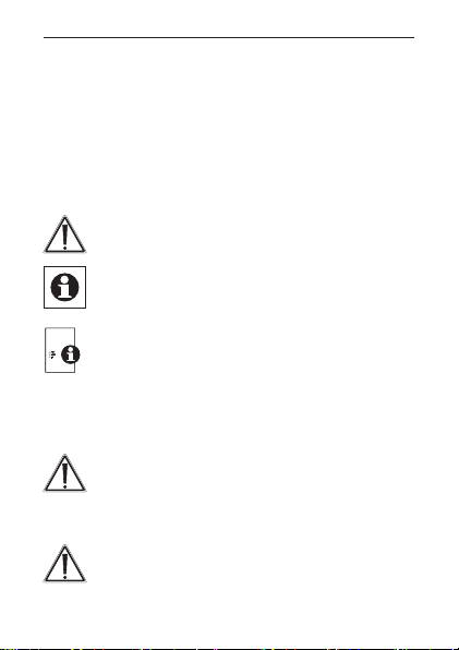
Symbols used:
Attention!
This indicates a hazard.
Note. This section contains important additional
information.
Note. This section contains additional important
information about using the device in connec-
tion with the HomeMatic Central Control Unit.
2 Hazard information
Do not open the device. It does not contain any
parts that can be maintained by the user. In the
event of an error, please return the device to our
service department.
For safety and licensing reasons (CE), unauthorized change and/or modication of the product is not permitted.
34
Hazard information
The device may only be operated in dry and
dust-free environment and must be protected
from the effects of moisture, vibrations, solar or
other methods of heat radiation, cold and mechanical loads.
The device is not a toy; do not allow children to
play with it. Do not leave packaging material lying around. Plastic lms/bags, pieces of polystyrene, etc. can be dangerous in the hands of a
child.
We do not assume any liability for damage to
property or personal injury caused by improper
use or the failure to observe the safety instructions. In such cases any claim under guarantee
is extinguished! For consequential damages,
we assume no liability!
This device operates using non-visible infra-red
light. Please keep a minimum distance of 20 cm
between the device and your eyes!
35

General information about the HomeMatic system
3 General information about the
HomeMatic system
This device is part of the HomeMatic home control system and works with the bidirectional BidCoS® wireless
protocol. All devices are delivered in a standard con-
guration. The functionality of the device can also be
congured with a programming device and software.
The additional functions that can be made available in
this way and the supplementary functions provided by
the HomeMatic system when it is combined with other
components are described in the HomeMatic WebUI
Manual. All current technical documents and updates
are provided at www.homematic.com.
4 Function and device overview
The HomeMatic Wireless Door/Window Sensor, optical detects open and closed windows and doors with
an infra-red sensor (reection coupler) and transmits
the current status via radio signal to other HomeMatic
devices or the HomeMatic Central Control Unit. Even
while being out and about you can keep a close eye to
your windows and doors.
The device offers different application options and can
be used e.g. with a HomeMatic Wireless Radiator Thermostat for regulation of the room temperature during
ventilation.
36
Function and device overview
Thanks to the two different caps, the colour of the device adapts to the door/window frames. Furthermore,
the door/window sensor can be easily mounted thanks
to the supplied adhesive stripes or screws.
The integrated temper contact sends an alarms e.g. to
the WebUI in case the cap is being removed.
Strong extraneous light and contamination of
the sensor can lead to functional disorders.
The Wireless Door/Window Sensor (HM-SecSCo) is not compatible with the HomeMatic
Wireless Alarm Central Unit (HM-Sec-Cen).
37
Function and device overview
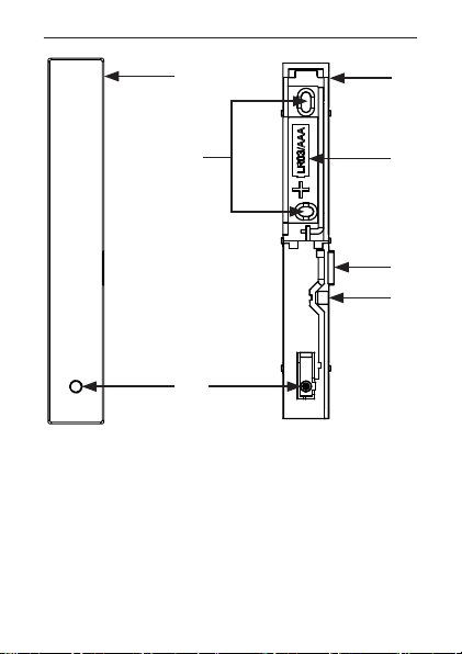
A
C
G
(A) Cap
(B) Electronic unit
(C) Screw holes
(D) Battery compartment
(E) Infra-red sensor (reection coupler)
(F) Tamper contact
(G) Device LED and teach-in button
38
B
D
E
F
Start-up
5 Start-up
5.1 Mounting
Please read this entire section before starting to
carry out the mounting procedure.
Do not yet place the cap!
5.1.1 Selecting a suitable mounting location
• Select a door or window for mounting the door/window sensor.
• Fasten the door/window sensor on the side of the
door/window where the handle is located, in the
upper third of the door/window frame (see „A„5.1.2
Adhesive stripe or screw mounting“ on page 40).
• The infra-red sensor (E) must point into the direction
of the door/window casement (see following gure).
The ideal spacing between the housing edge of
the door/window sensor and door/window case-
ment should be 3 mm (see following gure).
• If the door/window handle is located on the right
side you will have to turn around the door/window
sensor so that the infra-red sensor points into the
direction of the door/window casement also on this
side (see following gure).
39
 Loading...