


Montage- und Bedienungsanleitung
D
Funk-Fenster-Drehgriffkontakt
HM-Sec-RHS Seite 4 - 23
Installation and Operating Manual
GB
Radio-controlled window rotary
handle sensor
HM-Sec-RHS Seite 24 - 43

1. Ausgabe Deutsch 07/2007
Dokumentation © 2007 eQ-3 Ltd., Hong Kong
Alle Rechte vorbehalten. Ohne schriftliche Zustimmung des Herausgebers darf dieses Handbuch auch
nicht auszugsweise in irgendeiner Form reproduziert
werden oder unter Verwendung elektronischer, mechanischer oder chemischer Verfahren vervielfältigt
oder verarbeitet werden.
Es ist möglich, dass das vorliegende Handbuch
noch drucktechnische Mängel oder Druckfehler
aufweist. Die Angaben in diesem Handbuch werden
jedoch regelmäßig überprüft und Korrekturen in der
nächsten Ausgabe vorgenommen. Für Fehler technischer oder drucktechnischer Art und ihre Folgen
übernehmen wir keine Haftung.
Alle Warenzeichen und Schutzrechte werden anerkannt.
Printed in Hong Kong
Änderungen im Sinne des technischen Fortschritts
können ohne Vorankündigung vorgenommen
werden.
75643 / V 1.0
2

1. English edition 07/2007
Documentation © 2007 eQ-3 Ltd., Hong Kong
All rights reserved. No parts of this manual may be
reproduced or processed in any form using electronic, mechanical or chemical processes in part or in
full without the prior explicit written permission of
the publisher.
It is quite possible that this manual has printing
errors or defects. The details provided in this manual
are checked regularly and corrections are done in
the next edition. We do not assume any liability for
technical or printing errors.
All registered trade marks and copyrights are
acknowledged.
Printed in Hong Kong
We reserve the right to make changes due to technical advancements without prior notice.
75643 / V 1.0
3

Inhaltsverzeichnis
1 Hinweise zu dieser Anleitung . . . . . . . . . . . . . 5
2 Gefahrenhinweise
3 Funktion
4 Allgemeine Systeminformation zu HomeMatic
5 Allgemeine Hinweise zum Funkbetrieb
6 Montage des Fenster-Drehgriffkontakts
6.1 Lieferumfang
6.2 Montage
6.2.1 Überblick
6.2.2 Montage
7 Inbetriebnahme
7.1 Batterien einlegen und wechseln
7.1.1 Batterien einlegen
7.1.2 Batterien wechseln
7.1.3 Verhalten nach dem Einlegen der Batterien
7.2 Anlernen
8 Rückmeldungen durch die Geräte-LED
9 Zurücksetzen in den Auslieferungszustand
10 Fehlermeldungen
10.1 Schwache Batterie
10.2 Befehl nicht bestätigt
11 Wartung und Reinigung
12 Technische Daten
4
. . . . . . . . . . . . . . . . . . . . . . 5
. . . . . . . . . . . . . . . . . . . . . . . . . . . . . . 6
. . . . . 8
. . . . 9
. . . . . . . . . . . . . . . . . . . . . . . . . . 9
. . . . . . . . . . . . . . . . . . . . . . . . . . . . . 9
. . . . . . . . . . . . . . . . . . . . . . . . . . . . . 9
. . . . . . . . . . . . . . . . . . . . . . . . . . . . . 10
. . . . . . . . . . . . . . . . . . . . . . . 13
. . . . . . . . . 13
. . . . . . . . . . . . . . . . . . . . . 13
. . . . . . . . . . . . . . . . . . . . 14
. 15
. . . . . . . . . . . . . . . . . . . . . . . . . . . . . 16
. . . . 18
. 20
. . . . . . . . . . . . . . . . . . . . . . 21
. . . . . . . . . . . . . . . . . . . . 21
. . . . . . . . . . . . . . . . . . 22
. . . . . . . . . . . . . . . . 22
. . . . . . . . . . . . . . . . . . . . . 23
7
1 Hinweise zu dieser Anleitung
Lesen Sie diese Anleitung sorgfältig, bevor Sie ihre
HomeMatic Komponenten in Betrieb nehmen.
Bewahren Sie die Anleitung zum späteren Nachschlagen auf!
Wenn Sie das Gerät anderen Personen zur Nutzung
überlassen, übergeben Sie auch diese Bedienungsanleitung.
Benutzte Symbole:
Achtung! Hier wird auf eine Gefahr hingewiesen.
Hinweis. Dieser Abschnitt enthält zusätzliche
wichtige Informationen!
2 Gefahrenhinweise
Öffnen Sie das Gerät nicht, es enthält keine durch
den Anwender zu wartenden Teile.
Betreiben Sie das Gerät nur in Innenräumen und
vermeiden Sie den Einfluss von Feuchtigkeit, Staub
sowie Sonnen- oder andere Wärmebestrahlung.
5
3 Funktion
Der Fenster-Drehgriffkontakt ist ein mechanischer
Sensor, der die Griffstellung des Fenstergriffes detektiert. Damit ist eine Unterscheidung in geschlossen, gekippt oder geöffnet möglich. Die Information
über die Griffstellung wird per Funk übertragen. Die
Montage erfolgt ohne Beschädigungen des Fensters
unter dem Fenstergriff.
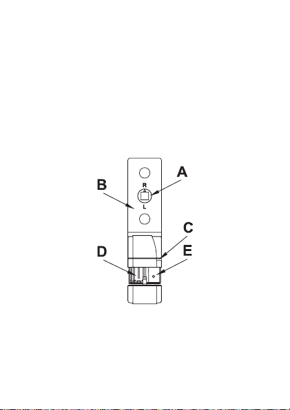
(A) Excenter
(B) Befestigungslasche (unter Fenstergriff)
(C) Geräte-LED
(D) Batteriefach
(E) Anlerntaste
6

4 Allgemeine Systeminformation
zu HomeMatic
Dieses Gerät ist Teil des HomeMatic Haussteuersystems und arbeitet mit dem bidirektionalen BidCoS®
Funkprotokoll.
Alle Geräte werden mit einer Standardkonfiguration
ausgeliefert. Darüber hinaus ist die Funktion des
Gerätes über ein Programmiergerät und Software
konfigurierbar. Welcher weitergehende Funktionsumfang sich damit ergibt, und welche Zusatzfunktionen sich im HomeMatic System im Zusammenspiel
mit weiteren Komponenten ergeben, entnehmen Sie
bitte der gesonderten Konfigurationsanleitung oder
dem HomeMatic Systemhandbuch.
Alle technischen Dokumente und Updates finden Sie
stets aktuell unter www.HomeMatic.com.
7

5 Allgemeine Hinweise zum Funk betrieb
Die Funk-Übertragung wird auf einem nicht exklusiven Übertragungsweg realisiert weshalb Störungen
nicht ausgeschlossen werden können.
Weitere Störeinflüsse können hervorgerufen werden
durch Schaltvorgänge, Elektromotoren oder defekte
Elektrogeräte.
Die Reichweite in Gebäuden kann stark
von der im Freifeld abweichen. Außer der
Sendeleistung und den Empfangseigenschaften der
Empfänger spielen Umwelteinflüsse wie Luftfeuchtigkeit neben baulichen Gegebenheiten vor Ort eine
wichtige Rolle.
Hiermit erklärt die eQ-3 Entwicklung GmbH, dass
sich dieses Gerät in Übereinstimmung mit den
grundlegenden Anforderungen und den anderen
relevanten Vorschriften der Richtlinie 1999/5/EG
befindet.
Die vollständige Konformitätserklärung finden Sie
unter www.HomeMatic.com.
8

6 Montage des Fenster-Drehgriff kontakts
6.1 Lieferumfang
• Tür-Fensterkontakt
• 2 Stück Knopfzellen LR44
• 2 Stück Senkkopfschrauben M5 x 35 mm,
Kreuzschlitz
6.2 Montage des Fenster-Drehgriffkontakts
6.2.1 Überblick
Bitte lesen Sie diesen Abschnitt erst vollständig,
bevor Sie mit der Montage beginnen.
Der Fenster-Drehgriffkontakt wird unter dem Fenstergriff montiert. Er wird dabei durch den Fenstergriff
gegen den Rahmen gepresst. Es sind keine zusätzlichen Bohrungen am Fenster notwendig (Siehe
Abbildungen).
9
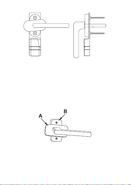
6.2.2 Montage
Demontieren Sie zunächst den Fenstergriff. Dazu
bringen Sie den Griff in waagerechte Position. Um
die Schrauben (B), die den Griff halten zu lösen
müssen Sie gegebenenfalls die Abdeckung (A) zur
Seite drehen (dabei ist u.U. ein leichtes Anheben der
Abdeckung notwendig).
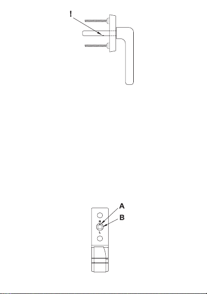
Sollten sich am Vierkant des Fenstergriffes Deformationen (durch mechanische Belastung, siehe ! in
nachstehender Abbildung) gebildet haben entfernen
Sie diese mit einer Pfeile.
10
Damit der Fenstergriff ohne den Fenster-Drehgriffkontakt zu beschädigen auf diesen aufgeschoben
werden kann, müssen alle Erhöhungen auf dem
Vierkant beseitigt werden.
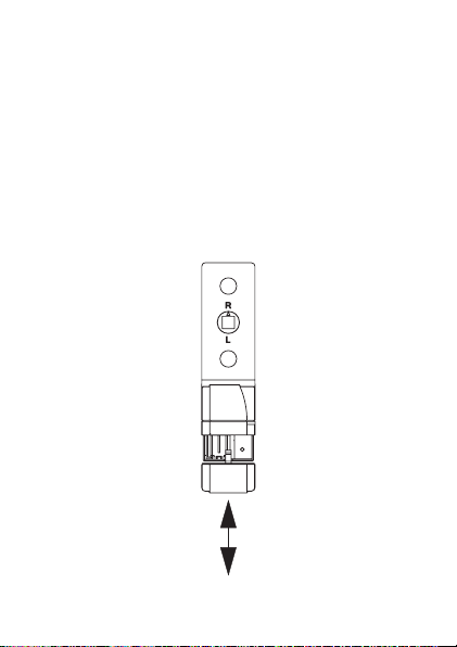
Der Fenster-Drehgriffkontakt ist für links und für
rechts angeschlagene Fenster geeignet. Sie müssen
vor der Montage des Fenster-Drehgriffkontakts die
Anschlagsseite einstellen. Dazu stellen Sie den Excenter (B) so ein dass der Pfeil (A) auf den entsprechenden Buchstaben R (für rechts angeschlagen)
und L (für links angeschlagen) weist.
11
Schieben Sie den Fenstergriff auf den Fenster-Drehgriffkontakt und montieren Sie den Griff wieder am
Fenster. Dabei muss der Fenstergriff in waagerechter Stellung stehen!
Setzen Sie nun die Befestigungsschrauben des
Griffs wieder ein und ziehen Sie die Schrauben fest.
Ziehen Sie die Schrauben nur mit sanftem
Druck fest. Der Excenter im Fenster-Drehgriffkontakt darf nicht so stark gequetscht werden,
dass er der Drehbewegung des Vierkants nicht mehr
folgt.
Normalerweise sind die Schrauben des Fens-
tergriffes lang genug. Sollte dieses nicht der
Fall sein, benutzen Sie die beiliegenden Schrauben.
Sollten diese ebenfalls nicht passen erwerben Sie
im Fachhandel 5 mm längere Schrauben als die
Originalschrauben. Falls der Vierkantstift nicht mehr
in die Fenstermechanik reicht (Fenstermechanik
bewegt sich nicht bei Griffbetätigung), kann der
Vierkant bei den meisten Griffen noch etwas herausgezogen werden.
12
7 Inbetriebnahme
7.1 Batterien einlegen und wechseln
Bitte lesen Sie diesen Abschnitt erst vollständig,
bevor Sie die Batterien einlegen bzw. wechseln.
Achten Sie nach dem Einlegen der Batterien auf die
Blinkzeichen der Geräte-LED.
7.1.1 Batterien einlegen
13

Schieben Sie den Batteriefachdeckel (Pfeil) nach
unten und nehmen ihn anschließend ab. Legen Sie
die mitgelieferten beiden Batterien LR44 polrichtig
entsprechend den Polaritätsmarkierungen in das
Batteriefach ein. Die Batterien werden durch die
Vorspannung der Batteriekontakte im Batteriefach
festgehalten.
Achten Sie nach dem Einlegen der Batterien auf
die Blinkzeichen der Geräte-LED (siehe Abschnitt
„Verhalten nach dem Einlegen der Batterien“).
Schließen Sie das Batteriefach wieder.
7.1.2 Batterien wechseln
Vorsicht! Explosionsgefahr bei unsachgemäßem
Austausch der Batterie.
Verbrauchte Batterien gehören nicht in
den Hausmüll! Entsorgen Sie diese in
Ihrer örtlichen Batteriesammelstelle!
Erfolgt beim Senden keine Reaktion des zu steuernden Gerätes oder wird der Blinkcode für leere Batterien angezeigt so sind die verbrauchten Batterien
wie im vorhergegangenen Kapitel beschrieben gegen
zwei neue Knopfzellen des Typs LR44 auszutauschen.
Beachten Sie dabei die richtige Polung der Batterien.
14

7.1.3 Verhalten nach dem Einlegen der Batterien
Nach dem Einlegen der Batterie führt der Sensor
zunächst einen Selbsttest durch. Dies dauert ca. 2
Sekunden. Danach erfolgt die Initialisierung. Den
Abschluss bildet die LED-Test-Anzeige: rot, grün,
orange jeweils für eine halbe Sekunde.
Tritt ein Fehler auf wird das durch rotes Blinken
signalisiert!
Danach sendet der Sensor eine Statusmeldung
– signalisiert durch orangenes Aufleuchten der
Geräte-LED. Bei angelernten Sensoren gefolgt von
einem grünen oder roten Blinken, je nachdem ob der
Empfang bestätigt wurde oder nicht.
Einmal langes, zweimal kurzes Blinken,
Pause
(2 Wiederholungen)
Einmal langes, einmal
kurzes Blinken, Pause
(endlos)
Batteriespannung zu
gering
Sensor defekt
15

Bei niedriger Batteriespannung wird, sofern es der
Spannungswert noch zulässt trotzdem der Sensor
aktiviert und ist betriebsbereit. Je nach Beanspruchung kann evtl. nach kurzer Erholungszeit der
Batterie wieder mehrfach gesendet werden. Bricht
beim Senden die Spannung wieder zu weit zusammen, wird wieder der entsprechende Fehlercode
angezeigt.
7.2 Anlernen
Bitte lesen Sie diesen Abschnitt erst vollständig,
bevor sie mit dem Anlernen beginnen!
Zum Anlernen müssen beide zu verknüpfende Geräte in den Anlernmodus gebracht werden.
Die Anlerntaste befindet sich auf der Vorderseite des
Gerätes unter der Batteriefachabdeckung. Damit die
Taste nicht versehentlich betätigt werden kann, ist
sie versenkt angeordnet.
16

Um den Fenster-Drehgriffkontakt in den Anlernmodus zu bringen, drücken Sie mit einem spitzen
Gegenstand auf die Anlerntaste. Die Geräte-LED
blinkt orange. (Abbruch durch kurze Betätigung der
Anlerntaste, die Geräte-LED leuchtet dann rot auf.)
Wenn kein Anlernen erfolgt, wird der Anlernmodus
automatisch nach 20 Sekunden beendet. Befinden
sich andere Geräte im Anlernmodus, werden diese
angelernt.
Erfolgreiches Anlernen wird durch ein grünes
Blinken signalisiert (Länge abhängig davon, ob noch
konfiguriert wird).
17

Hinweis: Ist der Sensor bereits an eine
Zentrale angelernt und damit für direktes Anlernen gesperrt, kann er zwar wie oben beschrieben
in den Anlernmodus gebracht werden, es erfolgt
jedoch kein Anlernen und die Geräte-LED leuchtet
rot auf.
grüne LED Anlernen erfolgreich
rote LED Anlernen fehlgeschlagen
Orangenes Blinken Sensor im Anlernmodus
Kurzes oranges
Blinken und rot oder
grün (je nach Erfolg)
Anderes Gerät im Anlernmodus und Sensor
in den Anlernmodus
gebracht.
8 Rückmeldungen durch die
Geräte-LED
Die Rückmeldungen gelten sowohl für den Betrieb
mit als auch ohne Zentrale.
Noch keine Aktoren angelernt:
Statusänderung: LED leuchtet für kurz auf
18

Aktoren sind angelernt:
Statusänderung: LED leuchtet orange so lange die
Funkübertragung andauert, diese Zeit ist abhängig
von der Anzahl an diese Taste angelernten Aktoren,
der Anzahl der benötigten Sendeversuche und vom
Verschlüsselungs- und Sendemodus. Nach Beendigung der Funkübertragung leuchtet die LED für eine
Sekunde rot oder grün auf.
Grün: alle Aktoren haben den (letzten) bidirektionalen Befehl bestätigt,
Rot: mindestens ein Aktor hat den (letzten) bidirektionalen Befehl nicht bestätigt.
Sensor im Sondermodus:
LED blinkt langsam orange: Anlernmodus (wartet
auf Funkpartner oder Parametrierung),
LED blinkt langsam rot: Vorstufe zum Rücksetzen in
Werkseinstellungen (wartet auf langen Tastendruck
der Anlerntaste zum Zurücksetzen, oder kurzen
Tastendruck zum Beenden).
LED blinkt schnell rot: Sensor wird in den Auslieferungszustand zurückgesetzt.
19

9 Zurücksetzen in den Ausliefe rungszustand
Halten Sie die Anlerntaste für mindestens 5 Sekunden gedrückt. Die LED des Sensors beginnt langsam rot zu blinken. (Wollen Sie an dieser Stelle das
Zurücksetzen abbrechen, können Sie das mit einem
kurzen erneuten Tastendruck auf die Anlerntaste
tun, oder Sie warten 15 Sekunden. In beiden Fällen
stoppt das langsame rote Blinken.)
Zum Zurücksetzen des Sensors drücken Sie nun
erneut für mindestens 5s die Anlerntaste. Die LED
beginnt nun während des gedrückt Haltens schneller
rot zu blinken. Loslassen schließt den Rücksetzvorgang ab und zur Bestätigung des Zurücksetzens
leuchtet die LED für etwa 3s dauerhaft rot auf.
Mögliche Fehlermeldungen:
(Dieser Fehler kann nur auftreten, wenn Sie
eine Zentrale besitzen und der Sensor an diese
Zentrale angelernt wurde.)
Beginnt die LED nach 5 Sekunden gedrückt Halten
nicht zu blinken, sondern leuchtet dauerhaft auf,
kann der Sensors nicht zurückgesetzt werden! In
diesem Falle ist die Verschlüsselung mit einem vom
20

Auslieferungsschlüssel verschiedenen System-Sicherheitsschlüssel aktiv. Um den Sensor zurückzusetzen müssen sie die Konfigurationssoftware
der Zentrale zum Zurücksetzen benutzen! Der
Vorgang ist in der Anleitung zur Zentralen-Software
beschrieben.
10 Fehlermeldungen
10.1 Schwache Batterie
Bei zu schwacher Batterie wird der entsprechende
Fehlercode (siehe Abschnitt „Batterien einlegen
wechseln“) angezeigt.
Sind die Batterien so schwach, dass mehrere Male
nacheinander ein Reset ausgelöst wurde, ohne dass
dazwischen erfolgreich gesendet wurde, wird bei
folgenden Tastendrücken nicht mehr gesendet, die
LED zeigt dann nur noch für 0,5 Sekunden rot an.
21

10.2 Befehl nicht bestätigt
Bestätigt ein Empfänger (bei mehreren angelernten
mindestens einer) einen Befehl nicht, leuchtet zum
Abschluss der Übertragung die Geräte-LED rot auf.
Der Fehler ist dann beim Empfänger zu suchen:
• Empfänger nicht erreichbar
• Empfänger kann Befehl nicht ausführen
(Lastausfall, mechanische Blockade etc.)
• Empfänger defekt
11 Wartung und Reinigung
Das Produkt ist für Sie bis auf einen eventuell erforderlichen Batteriewechsel wartungsfrei. Überlassen
Sie eine Wartung oder Reparatur einer Fachkraft.
Reinigen Sie das Produkt mit einem weichen, sauberen, trockenen und fusselfreien Tuch.
Für die Entfernung von stärkeren Verschmutzungen
kann das Tuch leicht mit lauwarmem Wasser angefeuchtet werden. Verwenden Sie keine lösemittelhaltigen Reinigungsmittel, das Kunststoffgehäuse und
die Beschriftung kann dadurch angegriffen werden.
22

12 Technische Daten
Funkfrequenz: 868,3 MHz
Typ. Freifeldreichweite: 100 m
Stromversorgung: 2 x Knopfzelle LR44
Batterielebensdauer: ca. 2 Jahre (4 Betäti
Schutzart: IP20
Gehäuse: ABS
Gehäusefarbe: Reinweiß
Abmessungen: 120 x 32 x 16 mm
(H x B x T)
Gewicht (Sensor und Magnet): 22 g (ohne Batterie)
Technische Änderungen vorbehalten.
Entsorgungshinweis:
Gerät nicht im Hausmüll entsorgen! Elektronische Geräte sind entsprechend der Richt-
linie über Elektro- und Elektronik-Altgeräte
über die örtlichen Sammelstellen für Elektronik-Altgeräte zu entsorgen.
Das CE-Zeichen ist ein Freiverkehrszeichen, das
sich ausschließlich an die Behörden wendet und
keine Zusicherung von Eigenschaften
gungen am Tag)
beinhaltet.
-
23

Table of Contents
1 Information concerning these instructions . 25
2 Hazard information
3 Function
4 General system information on HomeMatic
5 General information on radio operation
6 Installing the window rotary handle sensor
6.1 Scope of delivery
6.2 Installation
6.2.1 Overview
6.2.2 Installation
7 Start up
7.1 Installing and changing batteries
7.1.1 Installing batteries
7.1.2 Changing batteries
7.1.3 Behavior after inserting the batteries
7.2 Teaching
8 Device LED feedback
9 Resetting to factory status
10 Error messages
10.1 Weak battery
10.2 Command not confirmed
11 Maintenance and cleaning
12 Technical specifications
24
. . . . . . . . . . . . . . . . . . . . . . . . . . . . . 26
. . . . . . . . . . . . . . . . . . . . . . . . . . . . 29
. . . . . . . . . . . . . . . . . . . . . . . . . . . . . 33
. . . . . . . . . . . . . . . . . . . . . . . . . . . . 36
. . . . . . . . . . . . . . . . . . . . 25
. 27
. . . . 28
29
. . . . . . . . . . . . . . . . . . . . . 29
. . . . . . . . . . . . . . . . . . . . . . . . . . 29
. . . . . . . . . . . . . . . . . . . . . . . . . . . 30
. . . . . . . . . 33
. . . . . . . . . . . . . . . . . . . . . 33
. . . . . . . . . . . . . . . . . . . . 34
. . . . . . 35
. . . . . . . . . . . . . . . . . . 38
. . . . . . . . . . . . . . 40
. . . . . . . . . . . . . . . . . . . . . . . 41
. . . . . . . . . . . . . . . . . . . . . . . . . 41
. . . . . . . . . . . . . . . 42
. . . . . . . . . . . . . . 42
. . . . . . . . . . . . . . . . 43

1 Information concerning these
instructions
Read these instructions carefully before beginning
operation with your HomeMatic components. Keep
the instructions handy for later consultation!
Please hand-over the operating manual as well
when you hand-over the device to other persons
for use.
Symbols used:
Note! This indicates a hazard.
Note. This section contains additional impor-
tant information!
2 Hazard information
Do not open the device. It does not contain any
parts to be maintained by the user.
This device is to be operated indoors only and keep
away from the influences of humidity, dust and
sunshine or other radiating heat sources.
25

3 Function
The window rotary handle sensor is a mechanical
sensor that detects the grip position of the window
handle. This makes differentiating between closed,
tipped or open possible. The information concerning
the handle position is transferred via radio signal.
The installation is performed under the window
handle without any damage to the window.
(A) Excenter
(B) Fastening tab (under window handle)
(C) Device LED
(D) Battery compartment
(E) Teach button
26

4 General system information
on HomeMatic
This device is a part of the HomeMatic home control
system and works with the bidirectional BidCoS®
wireless protocol.
All devices are delivered in a standard configuration.
The functionality of the device can also be configured with a programming device and software.
Further resulting functionality and the additional
functions provided in the HomeMatic system
combined with other components are described in
the separate Configuration Instructions and in the
HomeMatic System Manual.
All current technical documents and updates are
provided under www.HomeMatic.com.
27

5 General information on radio
operation
The radio transmission is on a non-exclusive transmission path which means that there is a possibility
of interference occurring.
Other interfering sources can be caused by switching operations, electrical motors or defective
electrical devices.
The range of transmission within buildings
can greatly deviate from open air distances.
Besides the transmitting power and the reception characteristics of the receiver, environmental
influences such as humidity in the vicinity and local
structures also play an important role.
Hereby eQ-3 Entwicklung GmbH, declares that
this device conforms with the essential requirements and other relevant regulations of Directive
1999/5/EC.
The full declaration of conformity is provided under
www.HomeMatic.com.
28

6 Installing the window twist handle contact
6.1 Scope of delivery
• Door shutter contact
• 2 button cell batteries LR44
• 2 counter-sunk screws M5 x 35 mm, Phillips
recessed head
6.2 Installing the window rotary handle sensor
6.2.1 Overview
Please read this section completely before starting
any installation work!
The window rotary handle sensor is installed under
the window handle. It is pressed against the frame
through the window handle. No additional holes in
the window are required (see figures).
29

6.2.2 Installation
First, remove the window handle. This is done by
first moving the handle to a horizontal position. In
order to loosen the screws (B) that hold the handle
in place, you may have to turn the cover (A) to the
side (this may require slightly lifting the cover).
If deformations should appear on the square shaft
of the window handle (caused by mechanical stress,
see ! in the following figure), remove these with a
file.
30

In order to push the window handle against the window rotary handle sensor without damaging it, all
protrusions on the handle shaft must be removed.
The window rotary handle sensor is suitable for left
and right opening windows. The bolt-side must be
set-up before installing window rotary handle sensor. This is done by positioning the excenter (B) so
that the arrow (A) is pointed toward the respective
letter R (for right opening) and L (for left opening).
31

Push the window handle onto the window rotary
handle sensor and install the handle on the window
again. In this case, the window handle must be
positioned horizontally!
Now, insert the fastening screws of the handle again
and tighten the screws.
Tighten the screws until a slight amount of
pressure is evident. The excenter in the window rotary handle sensor is not to be squashed to
the point that it no longer follows the turning motion
of the handle shaft.
Normally, the screws of the window handle
are long enough. If this is not the case, use
the screws provided. If these do not reach either,
purchase screws that are 5 mm longer than the original screws from a specialized shop. If the handle
shaft not longer reaches into the window mechanics
(window mechanics will not move when the handle
is actuated), the shaft can be extended slightly on
most handles.
32

7 Start up
7.1 Installing and changing batteries
Please read this section completely before inserting
or changing the batteries.
Note the flashing signal of the device LED when the
batteries are inserted.
7.1.1 Installing batteries
33

Push the battery compartment cover (arrow)
downward and then remove it. Insert the two LR44
batteries provided with proper polarity according to
the polarity markings into the battery compartment.
The batteries are held in the battery compartment by
the tension on the battery caused by the contacts.
Note the flashing device LED when the batteries are
inserted (see section "Behavior after inserting the
batteries").
Close the battery compartment again.
7.1.2 Changing batteries
Caution! Danger of explosion if battery is replaced
improperly.
Used batteries are not to be disposed
of with the house-hold waste! Please
collection point!
If there is no reaction from the device that you want
to control when sending or if the flash-code for
empty batteries is shown, the used batteries are to be
replaced with two new button cells of type LR44 as
described in the previous chapter. Make sure that the
batteries are inserted with proper polarity.
34
dispose them at your local battery

7.1.3 Behavior after inserting the batteries
After inserting the battery, the sensor will run a
self-test. This runs for approx. 2 seconds. The
initialization runs next. The completion is indicated
with the LED test display: red, green, orange, each
for a half second.
If an error occurs, it is indicated with red flashing!
The sensor then sends a status message - indicated
by the device LED illuminated in orange. This is
followed by either read or green flashing when the
sensors have been taught, depending on whether
the reception has been confirmed or not.
One long flash, two
short flashes, pause
(repeated 2 times)
One long flash, one
short flash, pause
(infinite)
Battery power too low
Sensor defective
35

If the battery power is low, as long as the power
level allows, the sensor is activated and is ready for
operation. Depending on the requirements, the battery may recover and send again many times after
a short break. If the power drops too low when sending, the respective error code is displayed again.
7.2 Teaching
Please read this section completely before starting
with any teaching!
The two devices to be connected are set to teach
mode for teaching.
The teach button is located on the front of the
device under the battery compartment cover. This
button is located within a recess so that it cannot be
pressed accidentally.
36

To actuate teach mode on the window rotary handle
sensor, press the teach button with a pointed object.
The device LED flashes orange. (Abort with a short
press of the teach button, the device LED will then
illuminate in red.)
If no teaching occurs, teach mode is automatically
ended after 20 seconds. If other devices are in teach
mode, these are taught.
If learning is completed successfully, it is indicated
with the flashing green LED (length of time depends
on whether it is still configuring).
37

Note: If the sensor is already taught for a
center and therefore is blocked for direct training, it can still be put in teach mode as described
above but no teaching occurs and the device LED is
illuminated in red.
Green LED Teaching successful
Red LED Teaching failed
Orange flashing Sensor in teach mode
Brief orange flashing
and red or green
(depending upon
success)
Other device in teach
mode and sensor put in
teach mode.
8 Feedback by the device LED
The feedback signals apply for operation with and
without the center.
No actuators have been taught yet:
Status change: LED is briefly illuminated
38

Actuators are taught:
Status change: LED is illuminated in orange as long
as the function transfer requires, this time depends
on the number of actuators that have been taught
for this button, the number of required transmission
attempts and the encoding and transmission mode.
After the radio transmission is complete, the LED is
illuminated in either red or green for one second.
Green: all actuators have confirmed the (last) bidirectional command,
Red: at least one actuator has confirmed the (last)
bi-directional command.
Sensor in special mode:
LED flashes slowly in orange: Teach mode (waiting
for radio signal or parameter definition),
LED flashes slowly in red: Preparatory stage for
resetting to factory defaults (waiting for long button
press on the teach button for resetting, or brief
button press for ending).
LED flashes quickly in red: Sensor is reset to factory
status.
39

9 Resetting to factory status
Hold the teach button down for at least 5 seconds.
The sensor LED starts to flash slowly in red.
(If you want to abort the reset procedure at this
time, you can press the teach button briefly again
or wait 15 seconds. In either case, the flashing red
will stop.)
To reset the sensor, press the teach button again
for at least 5 seconds. The LED starts to flash in red
faster while the button is held down. Releasing the
button completes the reset procedure and the LED
is illuminated for approx. 3 seconds to confirm the
reset operation.
Possible error messages:
(This error can occur now if you have a center
and have taught the sensor for this center.)
If the LED does not start flashing after holding the
button down for 5 seconds but is illuminated continuously, the sensor cannot be reset! In this case,
the encoding is active using a system security key
that differs from the key delivered with the system.
40

In order to reset the sensor, you must use the
configuration software of the center for resetting!
The procedure is described in the center software
instructions.
10 Error messages
10.1 Weak battery
If the batteries are weak, the respective error code
(see section "Installing and changing batteries") is
shown.
If the batteries are so weak that a reset is triggered
several times in a row without transmitting successfully, no transmission will be made for following
button presses and the LED will only be illuminated
in red for 0.5 seconds.
41

10.2 Command not confirmed
If a receiver does not confirm a command (at least
one when more than one have been taught), the
device LED is illuminated in red when the transmission is complete. The error will then be found with
the receiver:
• Receiver not accessible
• Receiver cannot execute command
(load failure, mechanical blockage, etc.)
• Defective receiver
11 Maintenance and cleaning
The product is maintenance-free besides possibly
requiring a battery change. Maintenance or repairs
are only to be done by trained professionals. Clean
the product using a soft, clean, dry and lint-free
cloth.
To remote heavier contamination, make the cloth
damp with lukewarm water. Cleaning agents that
contain solvents are not to be used because it can
harm the plastic housing and the labels.
42

12 Technical specifications
Radio frequency: 868.3 MHz
Typ. outdoor range: 100 m
Power supply: 2 x button cell LR44
Battery lifespan: approx. 2 years
(4 actuations per day)
Protection type: IP20
Housing: ABS
Housing color: Pure white
Dimensions: 120 x 32 x 16 mm
(H x W x D)
Weight (Sensor and Magnet): 22 g (without battery)
Subject to technical changes.
Instructions for disposal:
Do not dispose off the device as part of
household garbage! Electronic devices are to
be disposed of in accordance with the guidelines concerning electrical and electronic devices via
the local collecting point for old electronic devices.
The CE sign is a free trade sign addressed
exclusively to the authorities and does not
include any warranty of any properties.
43

eQ-3 AG
Maiburger Straße 29
D-26789 Leer
www.eQ-3.com
44
 Loading...