


Montage- und Bedienungsanleitung (S. 2)
Mounting and operating manual (p. 37)
Funk-Display-Wandtaster, Aufputzmontage
Wireless Display Push-Button, surfacemount
HM-PB-4Dis-WM-2

2 3
1. Ausgabe Deutsch 07/2014
Dokumentation © 2014 eQ-3 Ltd., Hong Kong
Alle Rechte vorbehalten. Ohne schriftliche
Zustimmung des Herausgebers darf dieses
Handbuch auch nicht auszugsweise in irgendeiner
Form reproduziert werden oder unter Verwendung
elektronischer, mechanischer oder chemischer
Verfahren vervielfältigt oder verarbeitet werden.
Es ist möglich, dass das vorliegende Handbuch
noch drucktechnische Mängel oder Druckfehler
aufweist. Die Angaben in diesem Handbuch werden
jedoch regelmäßig überprüft und Korrekturen in der
nächsten Ausgabe vorgenommen. Für Fehler
technischer oder drucktechnischer Art und ihre
Folgen übernehmen wir keine Haftung.
Alle Warenzeichen und Schutzrechte werden
anerkannt.
Printed in Hong Kong
Änderungen im Sinne des technischen Fortschritts
können ohne Vorankündigung vorgenommen
werden.
140924/V 1.0
Inhaltsverzeichnis
1. Hinweise zu dieser Anleitung ..............4
2. Gefahrenhinweise ......................4
3. Funktion . . . . . . . . . . . . . . . . . . . . . . . . . . . . . . 6
4. Display, Bedienung, Menü ................8
5. Allgemeine Systeminformation zu HomeMatic 12
6. Allgemeine Hinweise zum Funkbetrieb .....13
7. Montage ............................. 14
8. Inbetriebnahme .......................17
9. Status Rückmeldungen .................31
10. Geräte-Namen und Schaltfunktionen.......31
11. Funktionen mit Zentrale . . . . . . . . . . . . . . . . . 33
12. Wartung und Reinigung .................34
13. Technische Eigenschaften . . . . . . . . . . . . . . . 35
4 5
1. Hinweise zu dieser Anleitung
Lesen Sie diese Anleitung sorgfältig, bevor Sie Ihre
HomeMatic Komponenten in Betrieb nehmen. Bewahren Sie die Anleitung zum späteren Nachschlagen auf!
Wenn Sie das Gerät anderen Personen zur Nutzung
überlassen, übergeben Sie auch diese Bedienungsanleitung.
Achtung!
Hier wird auf eine Gefahr hingewiesen.
Hinweis. Dieser Abschnitt enthält zusätzliche
wichtige Informationen!
2. Gefahrenhinweise
Bei Sach- oder Personenschäden, die durch
unsachgemäße Handhabung oder Nichtbeachten der Sicherheitshinweise verursacht werden,
übernehmen wir keine Haftung. In solchen Fällen erlischt jeder Gewährleistungsanspruch! Für
Folgeschäden übernehmen wir keine Haftung!
Öffnen Sie das Gerät nicht, es enthält keine
durch den Anwender zu wartenden Teile. Im
Fehlerfall schicken Sie das Gerät an den Service.
Aus Sicherheits- und Zulassungsgründen (CE)
ist das eigenmächtige Umbauen und/oder Verändern des Produktes nicht gestattet.
Betreiben Sie das Gerät nur in trockener sowie
staubfreier Umgebung, setzen Sie es keinem
Einuss von Feuchtigkeit, Vibrationen, ständiger Sonnen- oder anderer Wärmeeinstrahlung, Kälte und keinen mechanischen Belastungen aus.
Das Gerät ist kein Spielzeug! Erlauben Sie Kindern nicht damit zu spielen. Lassen Sie das
Verpackungsmaterial nicht achtlos liegen.
Plastikfolien/-tüten, Styroporteile etc. könnten
für Kinder zu einem gefährlichen Spielzeug
werden.
Jeder andere Einsatz als in dieser Bedienungsanleitung beschrieben ist nicht bestimmungsgemäß und führt zu Gewährleistungs- und Haftungsausschluss.
6 7
3. Funktion
3.1. Allgemeine Funktion
Der HomeMatic Funk-Display-Wandtaster dient zur
komfortablen Steuerung von HomeMatic Komponenten. Ein brillantes OLED-Display informiert Sie zusätzlich über den Status angelernter Geräte, beispielsweise ob das Licht in der Garage ein- oder ausgeschaltet
ist oder ein Schaltvorgang korrekt ausgeführt wurde.
Die Bezeichnungen für Räume und Komponenten
bzw. Funktionen sind frei editierbar, was eine präzise
Zuordnung ermöglicht. Über jeden der 10 Übertragungskanäle lassen sich bis zu 10 Komponenten
anlernen. Dies bietet Ihnen die Möglichkeit, mit einem
Tastendruck mehrere Funktionen auszuführen.
Die Stromversorgung des Aufputzgeräts erfolgt über
Batterien, sodass Sie den Wandtaster optimal überall
im Raum platzieren können.
3.2. Übersicht
Der Wandtaster besteht aus zwei Teilen:
A
B
(A) Wandtaster
(B) Montageplatte
8 9
3.3. Lieferumfang
• 1x HomeMatic Funk-Display-Wandtaster
• 1x Montageplatte
• 2x Klebestreifen
• 2x Holzschrauben 3,0 x 30 mm
• 2x Dübel 5 mm
• 3x LR03/Micro/AAA Batterien
• 1x Bedienungsanleitung
4. Display, Bedienung, Menü
4.1. Display-Aufteilung
C
D
E
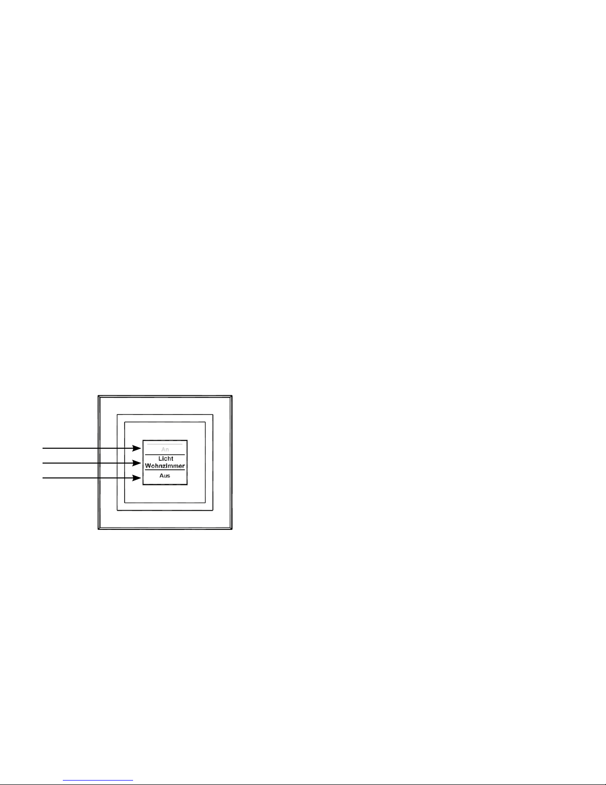
Das Display ist in 3 Bereiche unterteilt:
Der mittlere Bereich (D) gibt Informationen über den
Aktor und den Raum. Im vorherigen Abbildung ist für
einen Aktor der Name „Licht“ gewählt worden und
der Raum wurde als „Wohnzimmer“ bezeichnet. Die
Bezeichnungen können individuell angepasst werden
(siehe Abschnitt „8.3. Namen/Raum ändern“ auf Seite
22).
Im oberen (C) und unteren (E) Bereich sind die gegebenen Schaltmöglichkeiten dargestellt. Zu einem für
Lichtsteuerungen denierten Aktor gehören die Schaltmöglichkeiten „An“ und „Aus“. Bei der Aktor-Auswahl
KeyMatic würden z. B. die Schaltmöglichkeiten „Entriegeln“ und „Verriegeln“ angezeigt (siehe auch Abschnitt
„10. Geräte-Namen und Schaltfunktionen“ auf Seite
31).
Schaltvorgänge werden über das Display bestätigt.
Wenn eine Aktion (z. B. Licht einschalten) über den
Wandtaster ausgeführt wird, wird dies während des
Sendens zuerst mit einer orangen Darstellung des
Textes angezeigt. Erhält der Wandtaster die Rückmeldung vom Aktor, dass das Licht erfolgreich eingeschaltet wurde, wird der Text sogleich grün dargestellt. Für
den Fall, dass das Licht aus irgendwelchen Gründen
nicht eingeschaltet werden konnte, wird dies über einen roten Text angezeigt.
10 11
4.2. Allgemeine Bedienung und Menü
F
H
G
I
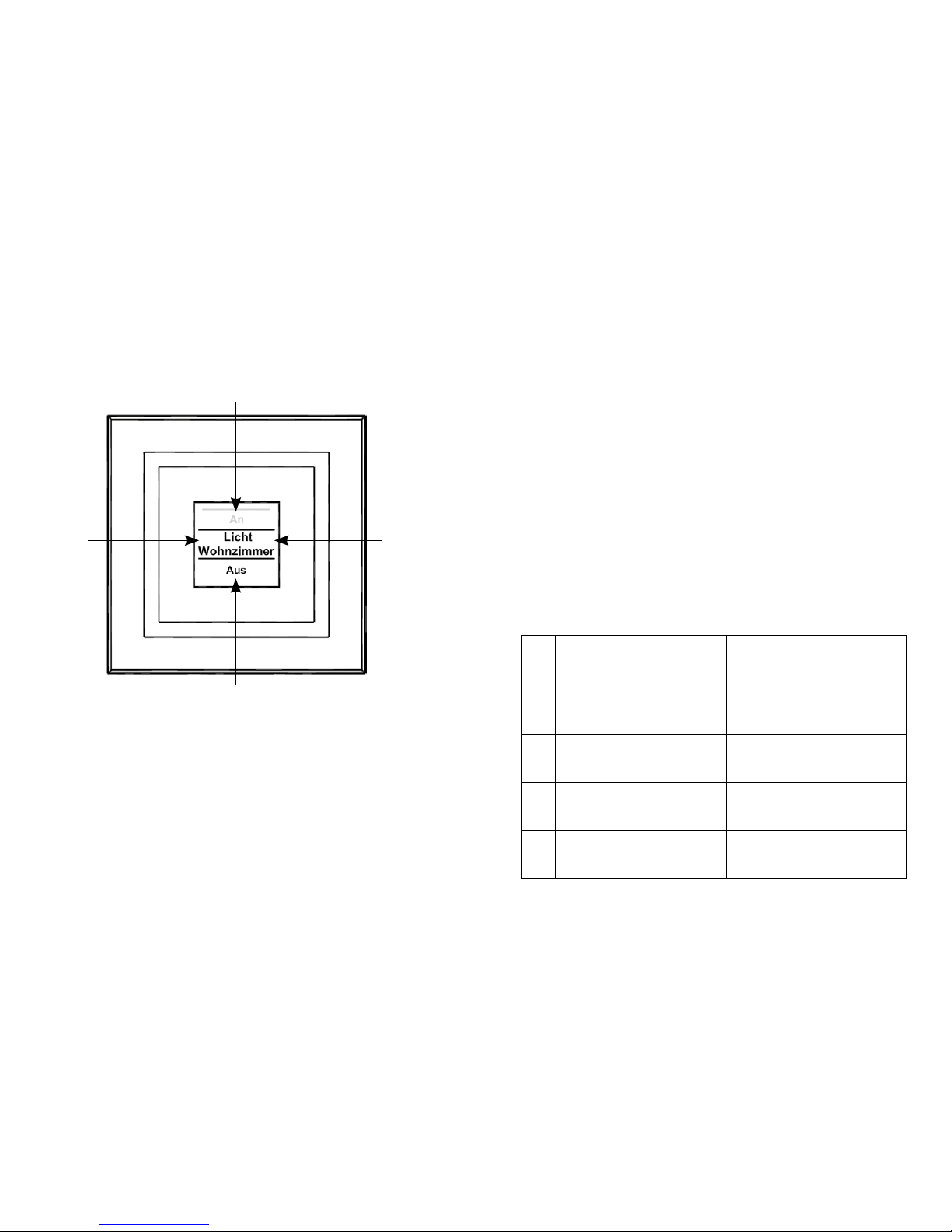
Die Tastwippe des Wandtasters kann in vier Richtungen gedrückt werden. Generell werden ein kurzer
(kürzer als 4 Sekunden) und ein langer Tastendruck
(länger als 4 Sekunden) unterschieden.
Über einen Tastendruck nach links (F) oder rechts (H)
können Sie die verschiedenen angelernten Geräte
bzw. Kanäle auswählen. Es können bis zu 10 Kanäle
(Position 1 bis 10) belegt werden.
Ein Tastendruck nach oben (I) oder unten (G) löst eine
Aktion aus. Generell ist oben (I) „Einschalten“ und
unten (G) „Ausschalten“. Ein langer Tastendruck löst
bei manchen Aktoren eine zusätzliche Funktion aus.
So wird z. B. bei einem Dimmer durch einen langen
Tastendruck nach oben oder unten das Licht stufenweise gedimmt.
Das Kongurations-Menü ist durch einen langen Tastendruck links (F) oder rechts (H) zu öffnen. Details
zum Kongurations-Menü entnehmen Sie bitte dem
Abschnitt „8. Inbetriebnahme“ auf Seite 17.
In der folgenden Tabelle werden die Tastenfunktionen
noch einmal übersichtlich dargestellt:
Kurzer
Tastendruck
Langer
Tastendruck
F
Geräte-/
Kanalauswahl
Menü öffnen
H
Geräte-/
Kanalauswahl
Menü öffnen
I
Schaltvorgang
auslösen
Schaltvorgang
auslösen
G
Schaltvorgang
auslösen
Schaltvorgang
auslösen
12 13
Display-Standby: Das Display geht nach
10 Sekunden in den Ruhezustand, um die Lebensdauer der Batterien zu maximieren.
Ein Druck auf eine der vier Seiten der Tastwippe reaktiviert das Display. Nach Reaktivierung
wird immer der erste Kanal bzw. Position 1 angezeigt. Die Zeit (Standby) ist wie in Abschnitt
8.7 beschrieben einstellbar.
Menü-Time Out: Das Kongurations-Menü
wird über einen langen Tastendruck (länger als
4 Sekunden) geöffnet. Nach 60 Sekunden Inaktivität schließt sich das Menü automatisch
und der Wandtaster springt zurück in die Bedienebene.
5. Allgemeine Systeminformation
zu HomeMatic
Dieses Gerät ist Teil des HomeMatic Haussteuersystems und arbeitet mit dem bidirektionalen BidCoS®
Funkprotokoll. Alle Geräte werden mit einer Stan-
dardkonguration ausgeliefert. Darüber hinaus ist die
Funktion des Gerätes über ein Programmiergerät und
Software kongurierbar. Welcher weitergehende Funk-
tionsumfang sich damit ergibt, entnehmen Sie bitte
dem HomeMatic WebUI Handbuch. Alle technischen
Dokumente und Updates nden Sie stets aktuell unter
www.homematic.com.
6. Allgemeine Hinweise zum Funkbetrieb
Die Funk-Übertragung wird auf einem nicht exklusiven
Übertragungsweg realisiert, weshalb Störungen nicht
ausgeschlossen werden können. Weitere Störeinüsse
können hervorgerufen werden durch Schaltvorgänge,
Elektromotoren oder defekte Elektrogeräte.
Die Reichweite in Gebäuden kann stark von
der im Freifeld abweichen. Außer der Sendeleistung und den Empfangseigenschaften der
Empfänger spielen Umwelteinüsse wie Luftfeuchtigkeit neben baulichen Gegebenheiten
vor Ort eine wichtige Rolle.
Hiermit erklärt die eQ-3 Entwicklung GmbH, dass sich
dieses Gerät in Übereinstimmung mit den grundlegenden Anforderungen und den anderen relevanten
Vorschriften der Richtlinie 1999/5/EG bendet. Die
vollständige Konformitätserklärung nden Sie unter
14 15
www.homematic.com.
7. Montage
Der Wandtaster ist ein Aufputz-Gerät und kann somit
überall nachträglich im Haus platziert werden.
Sie können zwischen zwei verschiedenen Montagearten wählen:
• Montage mit Schrauben
• Montage mit Klebestreifen
Wenn Sie den Wandtaster über bereits installierte Taster, Schalter oder Steckdosen
anbringen möchten, beachten Sie bitte dringend, dass im Normalfall die Stromleitungen
nach oben führen. Es besteht die Gefahr eines
elektrischen Schlages. In diesem Fall sollten
Sie eine Befestigung mit Klebestreifen wählen.
7.1. Montage mit Schrauben
Zur Schraubmontage gehen Sie wie folgt vor:
• Wählen Sie einen geeigneten Montageort aus.
• Stellen Sie sicher, dass in der Wand keine Leitungen
verlaufen.
J J
J
J
40.0
52,5
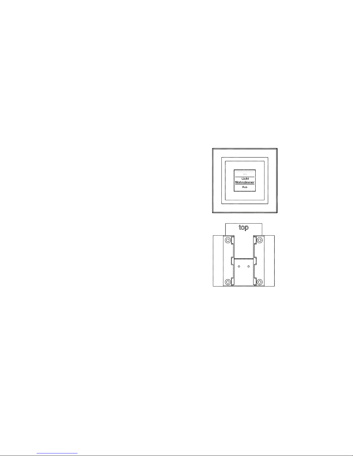
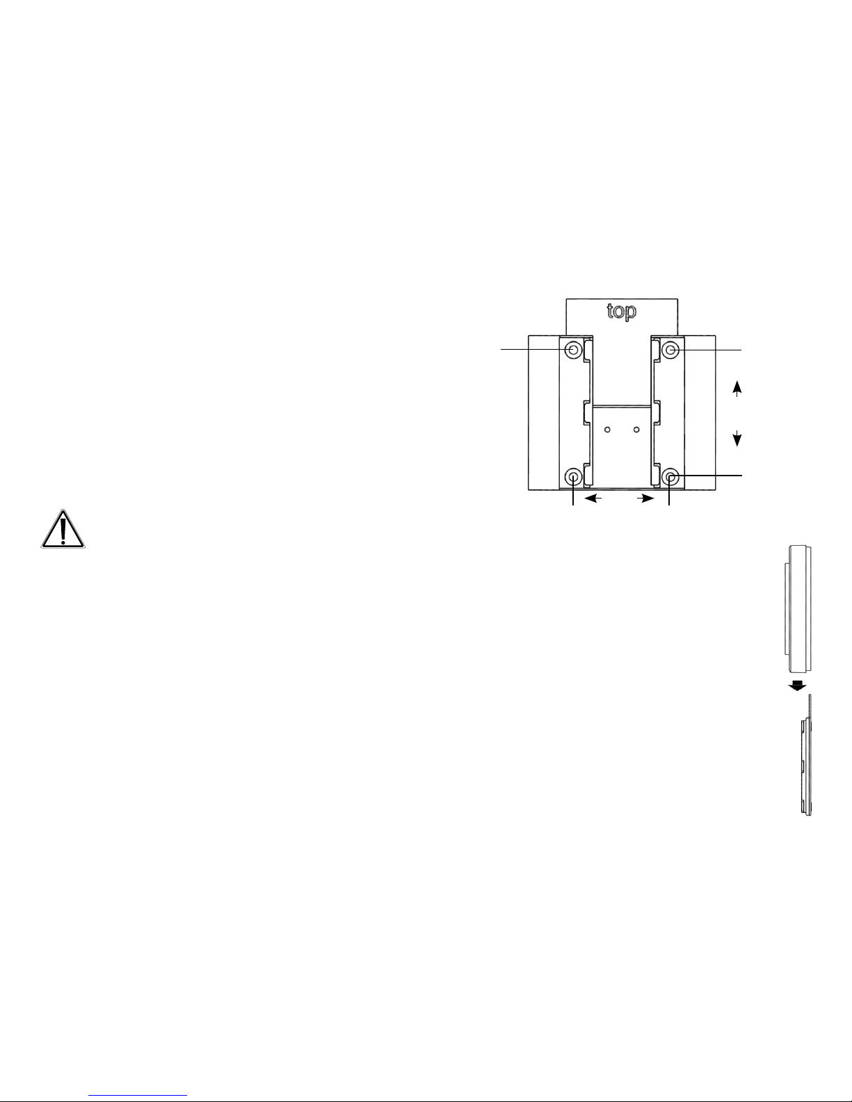
• Zuerst sind die vier Bohrlöcher (J) an der Wand
zu markieren. Wenn Sie die Montageplatte
dazu an die Wand halten, muss die Aufschrift
„top“ auf der sichtbaren Seite oben stehen.
• Bohren Sie bei einer Steinwand vier Löcher
von 5 mm und verwenden Sie die beiliegenden Dübel. Bei einer Holzwand können 1,5
mm zum leichteren Eindrehen der Schrauben
vorgebohrt werden.
• Drehen Sie die Schrauben ein.
• Der Wandtaster ist danach von oben auf die
Halterung zu schieben.
J

16 17
7.2. Montage mit Klebestreifen
Achten Sie darauf, dass der Montageuntergrund glatt, eben, unbeschädigt, sauber, fettsowie lösungsmittelfrei ist, damit der Klebestreifen langfristig haften kann.
Zum Befestigen mit Klebestreifen gehen Sie wie folgt
vor:
• Wählen Sie einen Ort zur Befestigung aus.
• Die Klebestreifen sind auf der Rückseite der Monta-
geplatte zu befestigen. (Nicht auf der Seite, auf der
das Wort „top“ steht.)
• Ziehen Sie dazu auf einer Seite der Klebestreifen
den Schutzlm ab. Die Laschen der Klebestreifen
müssen oben in den ausgesparten Bereichen (K)
überstehen.
K
K
• Ziehen Sie die Schutzfolie der zweiten Klebestreifenseite ab.
• Nun können Sie die Montageplatte des Wandtasters
am gewünschten Ort ankleben. Das Wort „top“ (L)
muss im angeklebten Zustand lesbar sein.
L
• Drücken Sie die Wandhalterung für einen kurzen
Moment fest gegen die Wand.
• Der Wandtaster ist danach von oben auf die Halterung aufzuschieben.
8. Inbetriebnahme
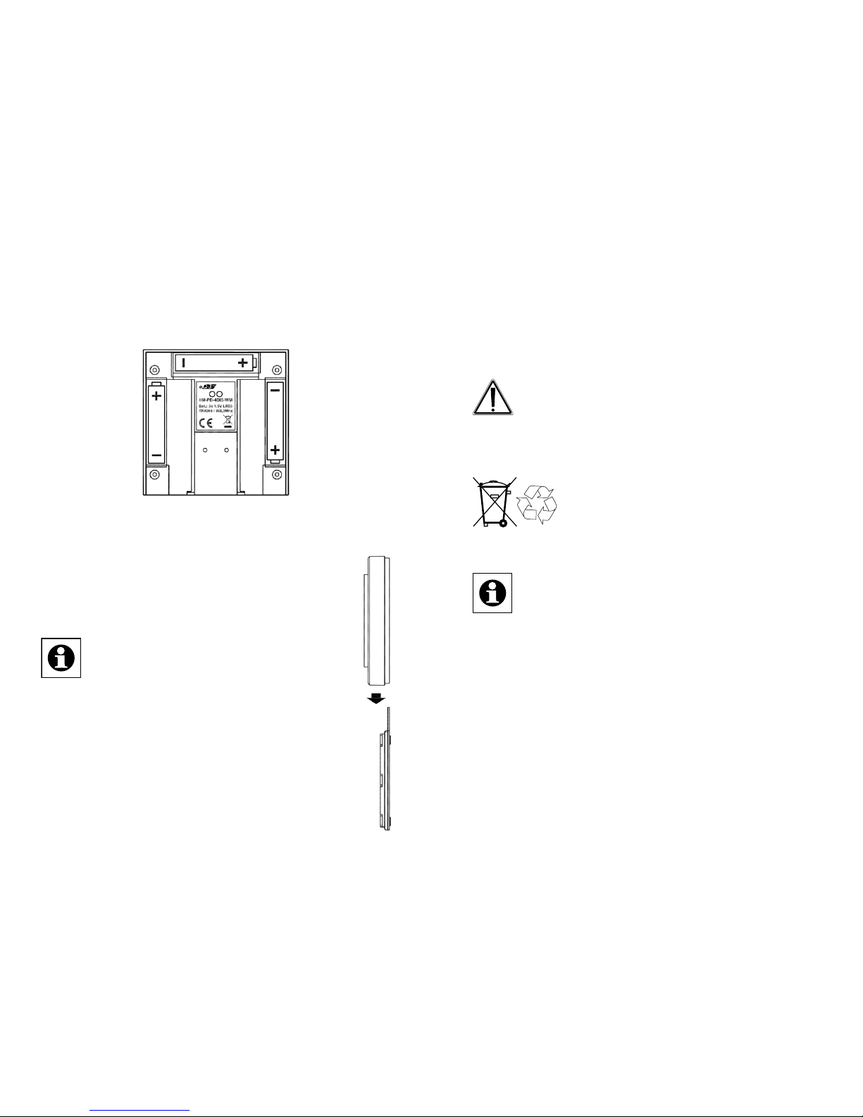
8.1. Batterien einlegen (wechseln)
Der Wandtaster wird mit 3 LR03/Micro/AAA Batterien
betrieben.
• Ziehen Sie den Wandtaster nach oben von der Montageplatte ab.
18 19
• Auf der Rückseite des Wandtasters sind die drei Batteriehalterungen zu sehen.
• Legen Sie 3 neue LR03/Micro/AAA Batterien polungsrichtig in die Batteriefächer ein.
•
Falls bereits montiert, ist der Wandtaster danach von oben auf die Montageplatte aufzuschieben.
Die Lebensdauer neuer Alkali-Batterien
beträgt ca. zwei Jahre. Die Batterielebensdauer ist von der Häugkeit der Bedienung (bzw. der Display-Aktivierung)
abhängig.
Wenn die Batterien auszutauschen sind, wird
dies im Display signalisiert. Nach Aktivierung
des Displays wird eine entsprechende Meldung
kurz eingeblendet. Wird das Gerät im Zusammenhang
mit einer HomeMatic Zentrale betrieben, wird auch
eine Service-Meldung an die Zentrale geschickt.
Batterien dürfen niemals aufgeladen werden.
Batterien nicht ins Feuer werfen. Batterien nicht
übermäßiger Wärme aussetzen. Batterien nicht
kurzschließen. Es besteht Explosionsgefahr!
Verbrauchte Batterien gehören nicht in
den Hausmüll! Entsorgen Sie diese in
Ihrer örtlichen Batteriesammelstelle!
8.2. Anlernen
Bitte lesen Sie diesen Abschnitt erst vollständig, bevor sie mit dem Anlernen beginnen!
Damit der Wandtaster in Ihr HomeMatic System
integriert werden und mit anderen HomeMatic Geräten kommunizieren kann, muss das Gerät zunächst
angelernt werden. Sie können den Wandtaster direkt
an andere HomeMatic Geräte oder an die HomeMatic
Zentrale anlernen.
Zum Anlernen gehen Sie wie folgt vor:
• Öffnen Sie das Kongurations-Menü durch einen
20 21
langen Tastendruck (mind. 4 Sekunden) nach links
oder rechts (<>).
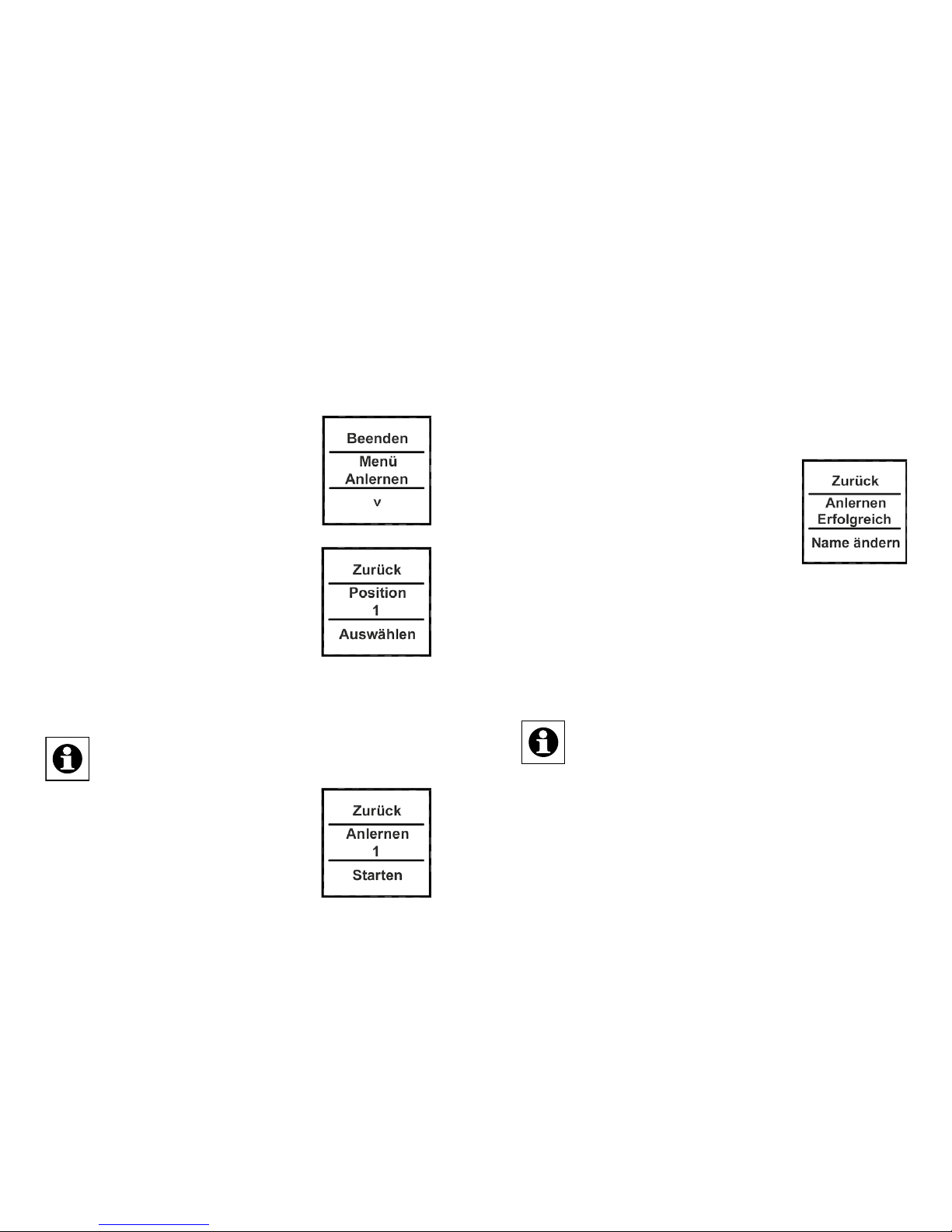
• Im Display wird die oberste Menü-Ebene eingeblendet. Mit einem Tastendruck nach links/rechts (<>)
können die verschiedenen Punkte
der Menü-Ebene ausgewählt werden.
• Wählen Sie den Punkt „Menü Anlernen“ mit einem Tastendruck nach
unten (˅) aus.
•
In der nächsten Menü-Ebene
können Sie mit Tastendrücken nach
links/rechts (<>) eine Speicherposition (Kanal) auswählen. Es wird zuerst die nächst freie Position zur
Auswahl gestellt.
• Bestätigen Sie die Auswahl mit einem Tastendruck
nach unten (˅).
Zum Anlernen an eine Zentrale ist der Eintrag
„Zentrale“ auszuwählen (Tastendruck <).
• Der Anlernvorgang kann nun mit
einem Tastendruck nach unten (˅)
aktiviert werden.
Der Wandtaster sucht dann für 20 Se-
kunden nach einer anderen HomeMatic Komponente,
die ebenfalls im Anlernmodus ist.
• Versetzen Sie innerhalb dieser Zeit auch das anzulernende Gerät (oder die Zentrale) in den Anlernmodus.
Nach erfolgreichem Anlernen können
Sie den Namen und die Raumbezeichnung ändern.
Nach dem Anlernen ist zunächst
„Position“ als Name hinterlegt und die
zugehörige Nummer als Raum.
• Mit Tastendrücken nach links/rechts (<>) können
Sie zwischen „Name ändern“ und „Raum ändern“
wechseln.
• Bestätigen Sie die Auswahl mit einem Tastendruck
nach unten (˅).
Nach der Auswahl kann ein vorgegebener
Name oder Raum ausgewählt werden oder Sie
denieren diese frei. Für Details lesen Sie Abschnitt „8.3. Namen/Raum ändern“ auf Seite
22.
22 23
Der Wandtaster verfügt über 10 Kanäle, im Folgenden auch Positionen genannt. An jeden Kanal können bis zu 10 HomeMatic Geräte angelernt werden. Sind mehrere Geräte an einen
Kanal angelernt, wird dies als Gruppe bezeichnet. Ein Schaltvorgang wird für alle Geräte der
Gruppe gleichzeitig ausgelöst.
8.3. Namen/Raum ändern
Für jedes am Wandtaster angelernte Gerät bzw. jeden
Kanal kann ein Name (z. B. Licht) und ein Raum (z. B.
Wohnzimmer) hinterlegt werden. Sie können aus einer
Auswahl vorgegebener Bezeichnungen wählen oder
einen individuellen Namen mit maximal 12 Zeichen
eingeben.
Die Änderung eines Namens oder einer Raumbezeichnung sind gleich und werden daher im Folgenden nur
einmal exemplarisch erklärt.
• Öffnen Sie das Kongurations-Menü durch einen
langen Tastendruck nach links oder rechts (<>).
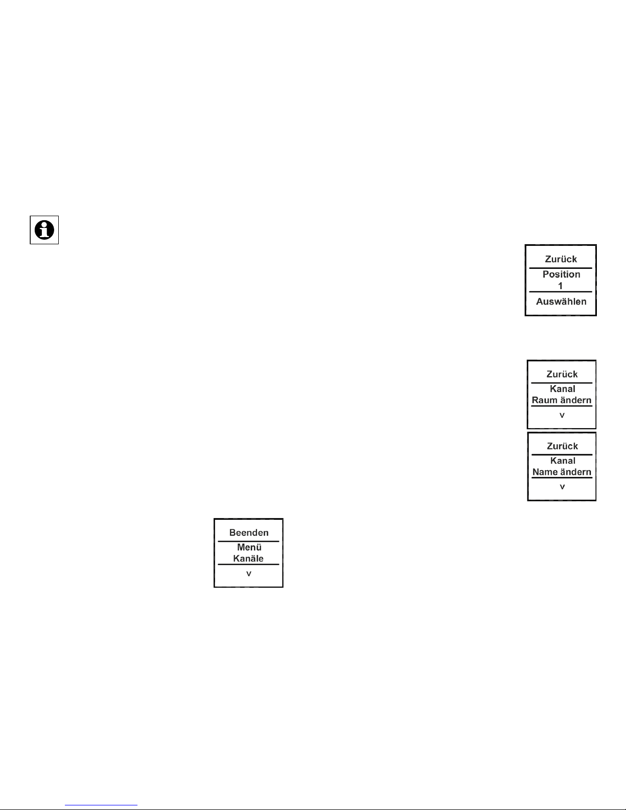
•
Im Display wird die oberste MenüEbene eingeblendet. Mit Tastendrücken nach links/rechts (<>) ist der
Punkt „Menü Kanäle“ auszuwählen.
• Mit einem Tastendruck nach unten
(˅) gelangen Sie in die nächste Menü-Ebene.
•
In der nächsten Menü-Ebene
können Sie mit Tastendrücken nach
links/rechts (<>) eine Speicherposition (Kanal) auswählen. Im Beispiel
ist es das Gerät mit Namen „Position“ im Raum „1“.
• Bestätigen Sie die Auswahl mit einem Tastendruck
nach unten (˅).
• Danach stehen Ihnen neben „Ab-
lernen“ die Punkte „Name ändern“
und „Raum ändern“ zur Verfügung.
• Wählen Sie (<>) den Punkt „Name
ändern“ oder „Raum ändern“ mit
einem Tastendruck nach unten (˅)
aus.
Im folgenden Beispiel ist der Punkt
„Name ändern“ ausgewählt. Das Vorgehen bei der Änderung einer Raum-Bezeichnung ist
identisch.
• Mit Tastendrücken nach links/rechts (<>) können Sie
die verschiedenen vorgegebenen Bezeich nungen

24 25
durchgehen.
•
Mit einem Tastendruck nach unten
(˅) wählen Sie einen Namen aus
und speichern diesen sogleich.
Im Beispiel rechts wurde die Bezeichnung „Licht“ ausgewählt.
Sie haben zusätzlich die Möglichkeit einen freien
Namen zu hinterlegen bzw. einen vorgegebenen zu
ändern. Dies ist fortfolgend erklärt.
Freie Namensvergabe/Editiermodus:
• Mit einem langen Tastendruck
(länger als 4 Sekunden) nach links
oder rechts (<>) wird der Editiermodus gestartet.
•
Mit Tastendrücken nach links/rechts
(<>) können Sie die 12 Ziffern einzeln anwählen. Mit Tastendrücken
nach oben/unten (˄˅) ändern Sie die
jeweilige Ziffer.
• Es kann zwischen Groß-/Kleinschreibung und Sonderzeichen gewechselt werden. Drü-
cken Sie dazu den Taster lang nach oben/unten (˄˅).
• Über einen langen Tastendruck nach links oder
rechts (<>) wird der Name gespeichert und der Edi-
tiermodus verlassen.
Im nebenstehenden Beispiel wurde
neben dem Namen auch die Raumbezeichnung geändert.
Mit dem auf Position/Kanal 1 angelernten Aktor wird somit das DekoLicht im Wohnzimmer geschaltet.
8.4. Ablernen
Am Wandtaster angelernte Geräte können auch wieder abgelernt werden. Das Ablernen erfolgt je Kanal/
Position. Zum Ablernen von Geräten gehen Sie wie
folgt vor:
• Öffnen Sie das Kongurations-Menü durch einen
langenTastendruck nach links oder
rechts (<>).
• Im Display wird die oberste MenüEbene eingeblendet. Mit Tastendrücken nach links/rechts (<>) ist der
Punkt „Menü, Kanäle“ auszuwählen.
• Mit einem Tastendruck nach unten (˅) gelangen Sie
in die nächste Menü-Ebene.
• In der nächsten Menü-Ebene können Sie mit Tasten-

26 27
drücken nach links/rechts (<>) eine
Speicherposition (Kanal) auswählen. Im Beispiel wurde das Gerät
„Deko Licht“ im Raum „Wohnzimmer“ ausgewählt.
• Bestätigen Sie Ihre Auswahl mit
einem Tastendruck nach unten (˅).
•
Wählen Sie anschließend mit
Tastendrücken nach links/rechts
(<>) den Punkt „Ablernen“ aus.
• Bestätigen Sie die Auswahl mit
einem Tastendruck nach unten (˅).
•
Danach erfolgt eine Sicherheitsabfrage.
• Das Ablernen (Löschen) muss bestätigt werden.
• Mit der Auswahl „Nein“ bzw. einem
Tastendruck nach oben (˄) beenden
Sie den Ablernvorgang.
• Mit „Ja“ bzw. einem langen Tastendruck (länger als
4 Sekunden) nach unten (˅) wird der Ablernvorgang
ausgeführt.
Wurden mehrere Geräte an einen Kanal bzw.
eine Position angelernt, werden diese gemein-
sam abgelernt. Andere Kanäle/Positionen bleiben unverändert bestehen.
8.5. Sprache auswählen
Im Wandtaster sind zur Bedienung und für Menüs
die Sprachen Deutsch und Englisch
hinterlegt. Zum Ändern der Sprache
gehen Sie wie folgt vor:
• Öffnen Sie das Kongurations-Menü
durch einen langen Tastendruck
nach links oder rechts (<>).
•
Mit Tastendrücken nach links/rechts
(<>) ist der Punkt „Menü, Einstellung“ auszuwählen.
• Mit einem Tastendruck nach unten
(˅) gelangen Sie in die nächste
Menü-Ebene.
• In der nächsten Menü-Ebene ist mit
Tastendrücken nach links/rechts
(<>) der Punkt „Sprache“ auszuwählen.
• Bestätigen Sie die Auswahl mit
einem Tastendruck nach unten (˅).
• Im Punkt Sprache kann nun mit einem Tastendruck
nach links/rechts (<>) die Sprache geändert werden.

28 29
• Die angezeigte Sprache ändert sich gleichzeitig im
Display.
• Bestätigen Sie Ihre Auswahl mit „Speichern“ bzw.
„Save“ (˅).
• Zum Verlassen ohne zu speichern drücken Sie „Zu-
rück“ bzw. „Back“ (˄).
8.6. Werkseinstellungen wiederherstellen
Die Werkseinstellungen des Wandtasters können wiederhergestellt werden.
Beim Wiederherstellen der Werkseinstellungen
gehen alle Verknüpfungen mit angelernten Geräten und vorgenommenen Einstellungen unwi-
derruich verloren.
Zum Wiederherstellen der Werkseinstellungen gehen Sie wie folgt vor:
• Öffnen Sie das Kongurations-Menü
durch einen langen Tastendruck
nach links oder rechts (<>).
• Danach ist mit Tastendrücken nach
links/rechts (<>) der Punkt „Menü, Einstellung“ auszuwählen.
• Mit einem Tastendruck nach unten (˅) gelangen Sie
in die nächste Menü-Ebene.
•
In der nächsten Menü-Ebene ist mit
Tastendrücken nach links/rechts (<>)
der Punkt „Werkseinst.“ auszuwählen.
• Bestätigen Sie die Auswahl mit
einem Tastendruck nach unten (˅).
• Das Wiederherstellen der Werkseinstellungen muss
bestätigt werden.
•
Mit der Auswahl „Nein“ bzw. einem
Tastendruck nach oben (˄) beenden
Sie den Vorgang.
• Mit „Ja“ bzw. einem langen Tastendruck (länger als 4 Sekunden) nach
unten (˅) werden die Werkseinstellungen wieder hergestellt.
8.7. Display-Standby Zeit einstellen
Das Display schaltet sich bei Inaktivität automatisch
aus, um die Lebensdauer der Batterien zu erhöhen.
Diese Zeit ist auf 10 Sekunden voreingestellt. Diese
Einstellung kann in einem Bereich von 1 bis 99 Sekunden eingestellt werden. Zum Ändern der Standby-Zeit
gehen Sie wie folgt vor:

30 31
• Öffnen Sie das Kongurations-Menü
durch einen langen Tastendruck
nach links oder rechts (<>).
• Danach ist mit Tastendrücken nach
links/rechts (<>) der Punkt „Menü,
Einstellung“ auszuwählen.
• Mit einem Tastendruck nach unten (˅) gelangen Sie
in die nächste Menü-Ebene.
•
In der nächsten Menü-Ebene ist mit
Tastendrücken nach links/rechts
(<>) der Punkt „Standby“ auszuwählen.
• Bestätigen Sie die Auswahl mit
einem Tastendruck nach unten (˅).
•
Die Standby-Zeit kann mit Tastendrücken nach links/rechts (<>) verändert werden. Durch einen langen
Tastendruck verstellt sich die Zeit im
10-Sekundentakt.
• Mit der Auswahl „Zurück“ bzw.
einem Tastendruck nach oben (˄) beenden Sie den
Vorgang ohne zu speichern.
• Mit „Speichern“ bzw. einem Tastendruck nach unten
(˅) wird die eingestellte Standby-Zeit gespeichert.
9. Status Rückmeldungen
Der Wandtaster als HomeMatic Komponente überträgt
Daten mittels BidCoS-Protokoll. Dieses bidirektionale
Protokoll ermöglicht es, dass sendende Geräte eine
Rückmeldung vom empfangenden Gerät erhalten.
Wird ein Schaltvorgang am Wandtaster durch einen
Tastendruck ausgelöst, wird dies im Display durch eine
orange Einfärbung der Schrift dargestellt. Nach einer
Rückmeldung vom empfangenden Gerät, dass der
Schaltvorgang ausgeführt wurde, wird die Schrift grün
dargestellt. Wenn der Empfänger den Schaltvorgang
nicht ausgeführt hat oder keine Funkverbindung aufgebaut werden konnte, wird dies durch eine rote Schrift
angezeigt.
10. Geräte-Namen und Schaltfunktionen
Jedem Gerät kann individuell ein Name zugewiesen werden. Mit der Zuweisung eines Namens wird
gleichzeitig die Beschriftung für die Schaltfunktionen
(Tastendruck oben und unten) festgelegt. Die folgende
Tabelle gibt einen Überblick über die zum Namen/Gerät zugehörigen Schaltfunktionen:

32 33
Gerät
Obere Schaltfunktion
Untere
Schaltfunktion
Aktor An Aus
Dimmer An Aus
Fenster Öffnen Schließen
Gruppe An Aus
Jalousie Auf Zu
KeyMatic Entriegeln Verriegeln
Licht An Aus
Markise Auf Zu
Tür Entriegeln Verriegeln
Verschluss Entriegeln Verriegeln
WinMatic Öffnen Schließen
Bei Dimmern oder z. B. Markisen lassen sich über
einen langen Tastendruck Prozentwerte einstellen. So
kann ein Dimmer z. B. auf 60 % hochgedimmt werden.
Diese Werte werden im Display kurzzeitig anstelle des
Raumes eingeblendet.
11. Funktionen mit Zentrale
Im Zusammenspiel mit einer HomeMatic Zentrale sind
noch weitere Funktionen gegeben. So können z. B.
Programme über den Wandtaster gestartet werden.
Die Konguration muss dann über die Kongurationsoberäche der Zentrale geschehen. Über eine Zentrale
können alle Namen frei vergeben werden. Zudem
könnten einem Tastenpaar auch unterschiedliche Geräte oder Programme zugeordnet werden (z. B. oben
„Licht an“, unten „Programm starten“). Dadurch erhöht
sich die Anzahl anlernbarer Komponenten auf 200.
Das Kongurations-Menü ist nur noch mit zwei Funktionen belegt:
(1) Zentrale: Mit der Funktion „Sync.“ werden die Kon-
gurationsdaten von einer Zentrale abgefragt. Haben
Sie Änderungen an der Konguration über die Zentrale
vorgenommen, müssen diese durch eine manuelle
Betätigung der „Sync.“ Funktion zum Wandtaster übertragen werden.
(2) Einstellung, Werkseinstellungen: Die Werkseinstellungen können weiterhin wie unter Abschnitt 8.6
beschrieben hergestellt werden.

34 35
Nachdem der Wandtaster an eine Zentrale angelernt wurde, können Geräte nicht mehr direkt
am Wandtaster ab- oder angelernt werden.
Dies muss über die Bedienoberäche der Zentrale geschehen.
12. Wartung und Reinigung
Das Produkt ist für Sie bis auf einen eventuell
erforderlichen Batteriewechsel wartungsfrei.
Überlassen Sie eine Wartung oder Reparatur
einer Fachkraft.
Reinigen Sie das Produkt mit einem weichen, sauberen, trockenen und fusselfreien Tuch. Für die Entfernung von stärkeren Verschmutzungen kann das Tuch
leicht mit lauwarmem Wasser angefeuchtet werden.
Achten Sie darauf, dass keine Feuchtigkeit in das Geräteinnere gelangt. Verwenden Sie keine lösemittelhaltigen Reinigungsmittel, das Kunststoffgehäuse und die
Beschriftung können dadurch angegriffen werden.
13. Technische Eigenschaften
Geräte-Kurzbezeichnung: HM-PB-4Dis-WM-2
Versorgungsspannung: 3x 1,5 V LR03/Micro/AAA
Stromaufnahme: 45 mA max.
Batterielebensdauer: 2 Jahre typ. (bei bis zu
10 Betätigungen je Tag)
Schutzart: IP20
Umgebungstemperatur: -10 bis +55 °C
Abmessungen (B x H x T): 83 x 83 x 18 mm
Gewicht: 100 g (inkl. Batterien)
Funkfrequenz: 868,3 MHz
Empfängerkategorie: SRD Category 2
Typ. Funk-Freifeldreichweite: > 100 m
Duty Cycle: < 1 % pro h
Protokoll: BidCoS
Display: OLED Vollgrak-Display
Maximale Anzahl
Anlernbarer Geräte: 100 ohne Zentrale
200 mit Zentrale
Technische Änderungen vorbehalten.

36 37
1st English edition 07/2014
Documentation © 2014 eQ-3 Ltd., Hong Kong
All rights reserved. This manual may not be
reproduced in any format, either in whole or in part,
nor may it be duplicated or edited by electronic,
mechanical or chemical means, without the written
consent of the publisher. Typographical and printing
errors cannot be excluded. However, the information
contained in this manual is reviewed on a regular basis
and any necessary corrections will be
implemented in the next edition. We accept no
liability for technical or typographical errors or the consequences thereof.
All trademarks and industrial property rights are acknowledged.
Printed in Hong Kong.
Changes may be made without prior notice as a
result of technical advances.
140924/V 1.0
Entsorgungshinweis
Gerät nicht im Hausmüll entsorgen! Elektronische Geräte sind entsprechend der Richtlinie
über Elektro- und Elektronik-Altgeräte über die
örtlichen Sammelstellen für Elektronik-Altgeräte zu entsorgen.
Hinweis auf Konformität
Das CE-Zeichen ist ein Freiverkehrszeichen,
das sich ausschließlich an die Behörden wendet und keine Zusicherung von Eigenschaften
beinhaltet.

38 39
Contents
1. Information about this manual ............39
2. Hazard information..................... 39
3. Function . . . . . . . . . . . . . . . . . . . . . . . . . . . . . 41
4. Display, operation, menu ................43
5. General information about the HomeMatic
system ..............................47
6. General information about radio operation... 48
7. Mounting.............................49
8. Start-up..............................52
9. Feedback statuses .....................65
10. Device names and switching functions .....66
11. Functions with a central control unit........ 67
12. Maintenance and cleaning ...............69
13. Technical data ........................ 70
1. Information about this manual
Read this manual carefully before starting to use your
HomeMatic components. Keep the manual so you
can refer to it at a later date should you need to. If you
hand over the device to other persons for use, please
hand over the operating manual as well.
Attention!
This indicates a hazard.
Note. This section contains important additional information.
2. Hazard information
We do not assume any liability for damage to
property or personal injury caused by improper
use or the failure to observe the safety instructions. In such cases any claim under warranty
is extinguished! For consequential damages,
we assume no liability!
Do not open the device. It does not contain any
parts that can be maintained by the user. In the

40 41
event of an error, please return the device to
our service department.
For safety and licensing reasons (CE), unau-
thorized change and/or modication of the
product is not permitted.
The device may only be operated in dry and
dust-free environment and must be protected
from the effects of moisture, vibrations, solar or
other methods of heat radiation, cold and mechanical loads.
The device is not a toy; do not allow children to
play with it. Do not leave packaging material lying around. Plastic lms/bags, pieces of polystyrene, etc. can be dangerous in the hands of
a child.
Using the device for any purpose other than
that described in this operating manual does
not fall within the scope of intended use and
shall invalidate any warranty or liability.
3. Function
3.1. General function
The HomeMatic Wireless Display Push-Button offers convenient control of HomeMatic components.
The brilliant OLED display informs about the status
of taught-in devices, e.g. if lights in the garage are
switched on or off or if a switching command has
been executed correctly. A precise allocation of single
rooms, components or functions is given as the de-
scriptions can be individually dened by the user. More
than 10 components can be taught-in via each of the
10 transmission channels. At the touch of a button several functions can be executed at the same time. As
the power supply is provided by batteries, the surface-
mounted device can be exibly installed anywhere in
the room.

42 43
3.2. Overview
The display push-button consists of two parts:
A
B
(A) Display push-button
(B) Mounting plate
3.3. Scope of delivery
• 1x HomeMatic Wireless Display Push-Button
• 1x Mounting plate
• 1x Adhesive strips for wall mounting
• 3x LR03/micro/AAA batteries
• 2x wood screws 3.0 x 30 mm
• 2x plugs 5 mm
4. Display, operation, menu
4.1. Display areas
C
D
E
The display is divided into 3 areas:
The central area (D) provides information about the

44 45
actuator and the room. In the previous gure, an actuator has been called “Light” and the room has been
named “Living room”. These names can be dened
in accordance with individual requirements (refer to
Section 8.3).
The available switching options are shown in the upper
(C) and lower (E) areas. An actuator to be used for
controlling lights would have the switching options
“On” and “Off” assigned to it. If KeyMatic were to be
selected as the actuator, the switching options “Unlock” and “Lock” would be shown instead, for example
(refer also to Section 10).
Switching operations are conrmed on the display. If
an action (such as switching on the light) is performed
via the display push-button, the display text will initially
be orange to indicate that the associated command
is being transmitted. If the display push-button recei-
ves feedback from the actuator conrming that the
light has been switched on successfully, the text will
immediately change to green. If the light could not be
switched on for any reason, this will be indicated by
the text changing to red.
4.2. General operation and menu
F
H
G
I
The rocker on the display push-button can be pressed
in four different directions. A general distinction is
also made between pressing and releasing the button
(button pressed for under 4 seconds) and pressing
and holding down the button (button pressed for more
than 4 seconds). Press the left (F) or right (H) of the
button to select one of the various taught-in devices or
channels. Up to 10 channels (positions 1 to 10) can be
assigned. Pressing the button at the top (I) or bottom
(G) triggers an action. Usually the top (I) switches a
device on and the bottom (G) switches it off. Pressing

46 47
the button and holding it down can trigger an additional
function for some actuators: with a dimmer, for example, pressing the button at the top or bottom and holding
it down will dim or brighten the light by degrees. The
conguration menu can be opened by pressing the
button on the left (F) or right (H) and holding it down.
For details on the conguration menu, please refer to
Section 8.
Press button
and release
Press button
and hold down
F Select device/
channel
Open menu
H Select device/
channel
Open menu
I Trigger switching
operation
Trigger switching
operation
G Trigger switching
operation
Trigger switching
operation
Display standby: The display switches to
standby mode after approximately 10 seconds
to maximise battery life. Pressing any one of
the four sides of the pushbutton rocker will re-
activate the display. On reactivation, the rst
channel or position 1 is displayed by default. The
(standby) time is set as described in Section 8.7.
Menu time-out: The conguration menu is ope-
ned by pressing the button and holding it down
(for longer than 4 seconds). After 60 seconds of
inactivity the menu closes automatically and the
display push-button returns to operation mode.
5. General information about the
HomeMatic system
This device is part of the HomeMatic home control
system and works with the bidirectional BidCoS® wireless protocol. All devices are delivered in a standard
conguration. The functionality of the device can also
be congured with a programming device and software.
The additional functions that can be made available in
this way and the supplementary functions provided by
the HomeMatic system when it is combined with other
components are described in the HomeMatic WebUI
Manual. You can nd the latest versions of all technical
documents and the latest updates at
www.homematic.com.

48 49
6. General information about radio
operation
Radio transmission is performed on a non-exclusive
transmission path, which means that there is a possibility of interference occurring. Interference can also
be caused by switching operations, electrical motors or
defective electrical devices.
The range of transmission within buildings can
differ greatly from that available in the open air.
Besides the transmitting power and the reception characteristics of the receiver, environmental factors such as humidity in the vicinity have
an important role to play, as do on-site structural/screening conditions.
eQ-3 Entwicklung GmbH hereby declares that this
device complies with the essential requirements and
other relevant regulations of Directive 1999/5/EC.
You can nd the full declaration of conformity at www.
homematic.com.
7. Mounting
The display push-button is a surface-mounting device,
so it can be retrotted anywhere in the home. You can
choose from two different types of mounting:
• mounting with screws
• mounting with adhesive strips
If you want to install the display push-button
above other pushbuttons, switches or sockets
that are already in place, you must bear in mind
the fact that current lines usually run upwards.
This means there is a risk of electric shock. In
such cases you should attach the display pushbutton with adhesive strips.
7.1. Mounting with screws
To mount the device on a wall, proceed as follows:
• Select a suitable mounting location.
• Make sure that no electricity or similar lines run in
the wall at this location.

50 51
J
J
J
J
40.0
52.5
• First of all, mark four bore hole positions (J)
on the wall. When you hold the mounting plate
against the wall, the inscription “top” must be
visible at the top edge.
• If you are working with a stone wall, drill four 5
mm holes and insert the plugs supplied. If you
are working with a wooden wall, you can predrill 1.5 mm holes to make the screws easier
to insert.
• Screw the screws in.
• Then slide the display push-button onto the
holder from above.
7.2. Mounting with adhesive strips
Make sure that the mounting surface is smooth,
solid, non-disturbed, free of dust, grease and
solvents to ensure long-time adherence.
To attach the display push-button with adhesive strips,
proceed as follows:
• Select a mounting location.
• Attach the adhesive strips to the rear of the moun-
ting plate. (Not on the side where the word “top” is
printed.)
• To attach the adhesive strips, remove the protective
lm from one side. The ends of the adhesive strips
must protrude from the cut-out areas (K) at the top of
the mounting plate.
K
K
J

52 53
• Pull the protective lm off the other side of the adhesive strips.
• You can now stick the mounting plate for the display
push-button onto the wall at the required site. When
the plate is stuck in place, the word “top” (L) must
be visible.
L
• Briey press the wall mount rmly against the wall.
• Then slide the display push-button onto the holder
from above.
8. Start-up
8.1. Inserting (replacing) batteries
The display push-button runs on 3x LR03/micro/AAA
batteries.
• Slide the display push-button up and off the mounting
plate.
• You will see the battery holders on the rear of the display push-button.
• Insert 3 new LR03/micro/AAA batteries in the
battery compartments (making sure that you insert them the right way round).
• If you have already attached the mounting plate
to the wall, slide the display push-button onto it
from above.
The service life of new alkaline batteries is
approximately two years. The battery life
will depend on how frequently operations
are carried out (or how often the display is
activated).
The display will indicate when it is time to replace
the batteries. When the display has been activa-
ted, a corresponding message will briey appear. If the

54 55
device is being operated in conjunction with a HomeMatic central control unit, a service message is sent to
the CCU too.
Never recharge standard batteries. Do not throw
the batteries into a re. Do not expose batteries
to excessive heat. Do not short-circuit batteries.
Doing so will present a risk of explosion.
Used batteries should not be disposed of
with regular domestic waste. Instead,
take them to your local battery disposal
point.
8.2. Teaching-in
Please read this section completely before starting with any teaching!
In order to enable communication between radio
components, the devices have to be taught-in to one
another. If you want to use the display push-button to
switch HomeMatic actuators, proceed as follows:
• Open the conguration menu by
pressing and holding down the button
on the left or right (<>) for more than
4 seconds.
• The top menu level appears on the display. Press
the button on the left/right (<>) to browse through the
different items in that menu level.
• Select the “teach-in” item menu by pressing the but-
ton at the bottom (˅) .
•
In the next menu level you can
select a storage position (channel)
by pressing the button on the left/
right (<>). The next available positi-
on is displayed for selection rst.
• Conrm your selection by pressing
the button at the bottom (˅).
In order to teach in at a central control unit, select the “Central control unit” entry (press button <).
•
You can now activate the teach-in
procedure by pressing the button at
the bottom (v).
For the next 20 seconds the display
push-button will search for another
HomeMatic component that is also in
teach-in mode.

56 57
• This means that the device (or the central control
unit) to be taught-in needs to be switched to teach-in
mode during this time too.
Once teaching-in has been completed successfully,
the device and room names can be changed.
•
After teaching-in has been completed,
“Position” is initially stored as the
name and the associated number is
stored for the room.
• Press the button on the left/right (<>)
to toggle between “Change name”
and “Change room”.
• Conrm your selection by pressing the button at the
bottom (˅).
Once you have made your selection you can
either choose a preset name or room, or dene
your own. For details on this, please refer to
Section 8.3.
The display push-button features 10 channels,
also referred to as “positions” in the following.
Up to 10 HomeMatic devices can be taught-in
to each channel. If several devices have been
taught-in to one channel, they are referred to
as a group. A switching operation will be triggered for all the devices in the group simultaneously.
8.3. Changing a name/room
A name (e.g. Light) and a room (e.g. Living room) can
be stored for every device taught-in to the display
push-button or for every channel.
You can choose from a selection of preset names
or enter a customised name with a maximum of 12
characters.
The name of a device and that of a room are changed
in the same way, so just one example is given below to
explain both processes.
• Open the conguration menu by pressing and holding down the button on the left or right (<>).
•
The top menu level appears on the
display. Press the button on the left/
right (<>) to select the menu item
“Channels”.
• Press the button at the bottom (˅) to
access the next menu level.

58 59
• In the next menu level you can select
a storage position (channel) by
pressing the button on the left/right
(<>). This example refers to the device called “Position” in room “1”.
• Conrm your selection by pressing
the button at the bottom (˅).
• Now you can select either “Teach-
out” or the “Change name” or “Change room” items.
• Select (<>) the “Change name” or
“Change room” item by pressing the
button at the bottom (˅) .
In the example below, the “Change
name” item has been selected. The
procedure for changing the name of a
room is the same.
•
Press the button on the left/right (<>)
to browse through the different preset names.
• Press the button at the bottom (˅)
to select a name and save it at the
same time.
In the example, the name “Light” has been selected.
You can also enter and save a customised name or
modify a preset name; this process is explained below.
Assigning customised names/Edit mode:
•
Launch edit mode by pressing and
holding down the button on the left
or right (<>) for more than 4 seconds.
• Press the button on the left/right (<>)
to select the 12 digits individually.
Press the button at the top/bottom
(˄˅) to change the corresponding digit.
• You can toggle between upper/lower
case and special characters by pressing and holding down the pushbut-
ton at the top/bottom (˄˅).
• Press and hold down the button on the left or right
(<>) to save the name and exit edit mode.
In the example on the right, both the
device and room names have been
changed.
The actuator taught-in to position/
channel 1 controls the decorative light

60 61
in the living room.
8.4. Teaching-out
Devices that have been taught-in to the wallmounting pushbutton can also be taught-out again. Teaching-out is performed separately for each channel/
position. To teach-out devices, proceed as follows:
•
Open the conguration menu by
pressing and holding down the button on the left or right (<>).
• The top menu level appears on the
display. Press the button on the left/
right (<>) to select the
“Channels menu” item.
• Press the button at the bottom (˅) to access the next
menu level.
•
In the next menu level you can
select a storage position (channel)
by pressing the button on the left/
right (<>). In this example, the “Decorative light” device in room “Living
room” has been selected.
• Conrm your selection by pressing the button at the
bottom (˅).
•
Now press the button on the
left/right (<>) to select the “Teachout” item.
• Conrm your selection by pressing
the button at the bottom (˅).
•
A conrmation prompt will then
appear.
• The teach-out (delete) procedure
needs to be conrmed.
• Select “No” or press the button at
the top (˄) to end the teach-out
procedure.
• Select “Yes” or press and hold down the button at
the bottom (˅) for more than 4 seconds to perform
the teach-out procedure.
If several devices have been taught-in to one
channel or position, they are all taught-out together. Other channels/positions remain unaffected by this teach-out procedure.
8.5. Selecting the language
The languages English and German are stored in the
display push-button for the purposes of operation and
menu display. To change the language, proceed as
follows:

62 63
• Open the conguration menu by
pressing and holding down the button on the left or right (<>).
• Press the button on the left/right
(<>) to select the menu item “Settings”.
•
Press the button at the bottom (˅) to
access the next menu level.
• In the next menu level select the
“Language” item by pressing the
button on the left/right (<>).
• Conrm your selection by pressing
the button at the bottom (˅).
•
Under the “Language” menu item
you can now change the language
by pressing the button on the left/
right (<>).
• The display language changes in
real time with the language setting.
• Conrm your selection by pressing “Save” (˅).
• To exit without saving your changes, press
“Back” (˄).
8.6. Restoring the factory settings
The display push-button can be reset to its initial state.
When the factory settings are restored, all links
to taught-in devices and all settings you have
made are lost and cannot be retrieved.
To restore the factory settings, proceed as follows:
•
Open the conguration menu by
pressing and holding down the button on the left or right (<>).
• Then press the button on the left/
right (<>) to select the menu item
“Settings”.
• Press the button at the bottom (˅) to access the next
menu level.
• In the next menu level select the
“Factory set.” item by pressing the
button on the left/right (<>).
• Conrm your selection by pressing
the button at the bottom (˅).
•
You must conrm that you want to
restore the factory settings.
• Select “No” or press the button at the
top (˄) to end the procedure.

6564
• Select “Yes” or press and hold down the button at
the bottom (˅) for more than 4 seconds to restore the
factory settings.
8.7. Setting the display standby time
After a period of inactivity the display switches off automatically in order to maximise battery life. This time
period is preset to 10 seconds. This setting can be adjusted within a range from 1 to 99 seconds. To change
the standby time, proceed as follows:
•
Open the conguration menu by
pressing and holding down the button on the left or right (<>).
• Then press the button on the left/
right (<>) to select the “Settings
menu” item.
• Press the button at the bottom (˅) to access the next
menu level.
• In the next menu level select the
“Standby” item by pressing the button on the left/right (<>).
• Conrm your selection by pressing
the button at the bottom (˅).
•
You can change the standby time
by pressing the button on the left/
right (<>). Press the button and hold
it down to change the time in increments of 10 seconds.
• Select “Back” or press the button at
the top (˄) to end the procedure without saving your
changes.
• Select “Save” or press the button at the bottom (˅) to
save the standby time you have just set.
9. Feedback statuses
As a HomeMatic component, the display push-button
transmits data via the BidCoS protocol. This bidirectional protocol allows transmitting devices to receive
feedback from receiving devices.
If the display push-button is pressed to trigger a switching operation, this is indicated on the display by the
text turning orange. Once the receiving device has is-
sued feedback conrming that the switching operation
has been performed, the text changes to green. If the
receiver has not carried out the switching operation or
if no wireless connection could be established, this is
indicated by the text turning red.

66 67
10. Device names and switching
functions
A name can be assigned to each individual device.
The designations of the switching functions (when the
button is pressed at the top or the bottom) are dened
when the name is assigned.
The table below provides an overview of which switching functions belong to which name/device:
Device
Top switching
function
Bottom switching
function
Actuator On Off
Dimmer On Off
Window Open Close
Group On Off
Blinds
Open Close
KeyMatic Unlock Lock
Light On Off
Canopy Open Close
Door Unlock Lock
Lock Unlock Lock
WinMatic Open Close
For dimmers or canopies, for example, you can set
percentage values by pressing the button and
holding it down. This means that a dimmer can be
made brighter until it reaches 60 % of its full brightness, for example. These values appear on the display
briey, in place of the room data.
11. Functions with a central control
unit
Even more functions are available if you use the display push-button in conjunction with a HomeMatic central control unit, for example you can start programs
from the device. In such cases, the conguration
settings must be made via the conguration interface
of the central control unit. All names can be freely
assigned by means of a central control unit. In addition, different devices or programs can be allocated
to a pair of buttons (e.g. “Light on” at the top, “Start
program” at the bottom). This increases the number of
components that can be taught-in to 200.
However, the conguration menu still only has two
functions assigned to it:
(1) Central control unit: The “Sync.” function queries
conguration data from a central control unit. If you

68 69
have made changes to the conguration on the
central control unit, you will need to transfer them to
the display push-button by activating the “Sync.” function manually.
(2) Settings, factory settings: The factory settings can
still be restored as described in Section 8.6.
Once the display push-button has been taughtin to a central control unit, it will no longer be
possible to teach devices in to or out from the
display push-button directly. This must be done
via the central control unit’s user interface.
12. Maintenance and cleaning
This product does not require you to carry out
any maintenance other than replacing the battery when necessary. Enlist the help of an expert to carry out any maintenance or repairs.
Clean the product using a soft, lint-free cloth that is
clean and dry. You may dampen the cloth a little with
lukewarm water in order to remove more stubborn
marks. Make sure that no moisture will ingress into
the housing. Do not use any detergents containing
solvents, as they could corrode the plastic housing
and label.

70 71
13. Technical data
Device short name: HM-PB-4Dis-WM-2
Supply voltage: 3x 1.5 V LR03/micro/AAA
Current consumption: 45 mA max.
Battery life: 2 years typ. (at up to 10
operations per day)
Degree of protection: IP20
Ambient temperature: -10 to +55 °C
Dimensions (W x H x D): 83 x 83 x 18 mm
Weight: 100 g (incl. batteries)
Radio frequency: 868.3 MHz
Receiver category: SRD category 2
Typ. open area RF range: > 100 m
Duty cycle: < 1 % pro h
Protokoll: BidCoS
Display: OLED fully graphical
display
Max. number of devices
that can be taught-in: 100 without a CCU
200 with a CCU
Subject to technical changes.
Instructions for disposal
Do not dispose of the device with regular domestic waste. Electronic equipment must be
disposed of at local collection points for waste
electronic equipment in compliance with the
Waste Electrical and Electronic Equipment Directive.
The CE Marking is simply an ofcial symbol relating to the free movement of a product; it
does not warrant a product’s characteristics.

72
eQ-3 Entwicklung GmbH
Maiburger Straße 36
D-26789 Leer
www.eQ-3.de
 Loading...