


Montage- und
Bedienungsanleitung (S. 2)
Mounting instruction and
operating manual (p. 34)
Funk-Wandtaster mit Display
4fach:
Radio push-button 4-gang with
display wall-mount:
HM-PB-4Dis-WM

1. Ausgabe Deutsch 02/2010
Dokumentation © 2009 eQ-3 Ltd., Hong Kong
Alle Rechte vorbehalten. Ohne schriftliche
Zustimmung des Herausgebers darf dieses
Handbuch auch nicht auszugsweise in irgendeiner
Form reproduziert werden oder unter Verwendung
elektronischer, mechanischer oder chemischer
Verfahren vervielfältigt oder verarbeitet werden.
Es ist möglich, dass das vorliegende Handbuch
noch drucktechnische Mängel oder Druckfehler
aufweist. Die Angaben in diesem Handbuch werden
jedoch regelmäßig überprüft und Korrekturen in der
nächsten Ausgabe vorgenommen. Für Fehler
technischer oder drucktechnischer Art und ihre
Folgen übernehmen wir keine Haftung.
Alle Warenzeichen und Schutzrechte werden
anerkannt.
Printed in Hong Kong
Änderungen im Sinne des technischen Fortschritts
können ohne Vorankündigung vorgenommen
werden.
90218 / V 1.2
2

Inhaltsverzeichnis
1 Hinweise zu dieser Anleitung .............4
2 Gefahrenhinweise ......................4
3 Funktion..............................5
3.1 Allgemeine Funktion ....................5
3.2 Übersicht .............................5
3.3 Lieferumfang ..........................6
4 Display, Bedienung, Menü ............... 7
4.1 Display-Aufteilung......................7
4.2 Allgemeine Bedienung und Menü .........8
5 Allgemeine Systeminformation
zu HomeMatic ........................10
6 Allgemeine Hinweise zum Funkbetrieb ....11
7 Montage.............................12
7.1 Montage mit Schrauben ................12
7.2 Montage mit Klebestreifen ..............13
8 Inbetriebnahme .......................15
8.1 Batterien einlegen (wechseln)............15
8.2 Anlernen.............................16
8.3 Namen / Raum ändern .................19
8.4 Ablernen ............................22
8.5 Sprache auswählen.................... 24
8.6 Werkseinstellungen wieder herstellen .....25
8.7 Display-Standby Zeit einstellen .......... 26
9 Status Rückmeldung................... 28
10 Geräte-Namen und Schaltfunktionen...... 28
11 Funktionen mit Zentrale ................30
12 Wartung und Reinigung ................31
13 Technische Eigenschaften ..............31
3
1 Hinweise zu dieser Anleitung
Lesen Sie diese Anleitung sorgfältig, bevor Sie ihre
HomeMatic Komponenten in Betrieb nehmen.
Bewahren Sie die Anleitung zum späteren Nachschlagen auf! Wenn Sie das Gerät anderen Personen
zur Nutzung überlassen, übergeben Sie auch diese
Bedienungsanleitung.
Achtung! Hier wird auf eine Gefahr
hingewiesen.
Hinweis. Dieser Abschnitt enthält zusätzliche
wichtige Informationen!
2 Gefahrenhinweise
Betreiben Sie das Gerät nur in Innenräumen und
vermeiden Sie den Einfluss von Feuchtigkeit, Staub
sowie Sonnen- oder andere Wärmebestrahlung.
Jeder andere Einsatz als in dieser Bedienungsanleitung beschrieben ist nicht bestimmungsgemäß und
führt zu Garantie- und Haftungsausschluss.
Öffnen Sie das Gerät nicht, es enthält keine
durch den Anwender zu wartenden Teile. Im
Fehlerfall schicken Sie das Gerät an den Service.
4
3 Funktion
3.1 Allgemeine Funktion
Wandtaster dienen der Ansteuerung von Empfängern, die an sie angelernt sind. Der Wandtaster
verfügt zudem über ein Display, das den Namen
sowie den Raum eines angelernten Geräts anzeigt
und Statusmeldungen über ausgeführte Funkbefehle
ausgibt.
Der Wandtaster verfügt über 10 Kanäle, an die jeweils 1 bis 10 Komponenten angelernt werden können. Dadurch lassen sich mehrere Aktionen mit nur
einem Tastendruck ausführen.
Grundfunktionen und Namen von Aktoren/Räumen
können direkt am Wandtaster eingestellt werden.
Der Wandtaster ist ein Aufputzgerät, somit lässt er
sich nachträglich ganz leicht überall im Haus platzieren.
3.2 Übersicht
Der Wandtaster
besteht aus zwei Teilen:
A
5
B
(A) Wandtaster
(B) Montageplatte
3.3 Lieferumfang
• Wandtaster
• Montageplatte
• Klebestreifen zur Wandmontage
• 3 LR03 Batterien (Micro/AAA)
• 2 Holzschrauben 3,0 x 30 mm
• 2 Dübel 5 mm
6
4. Display, Bedienung, Menü
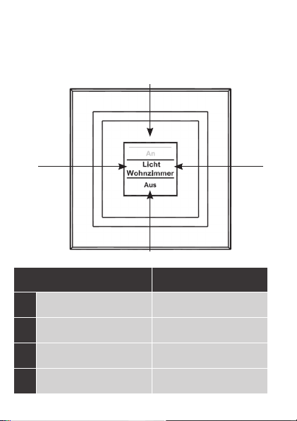
4.1 Display-Aufteilung
a
b
c
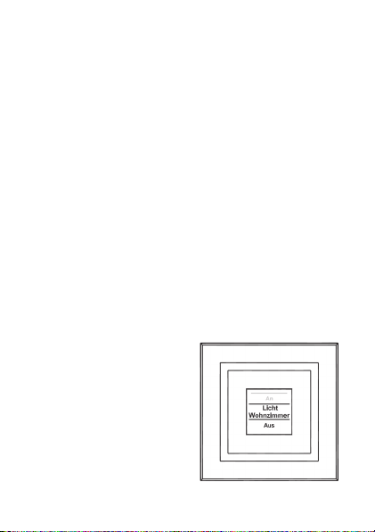
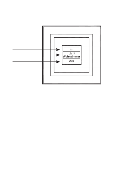
Das Display ist in 3 Bereiche unterteilt:
Der mittlere Bereich (b) gibt Informationen über
den Aktor und den Raum. Im obigen Beispiel ist für
einen Aktor der Name „Licht“ gewählt worden und
der Raum wurde als „Wohnzimmer“ bezeichnet.
Die Bezeichnungen können individuell angepasst
werden (siehe Abschnitt 8.3).
Im oberen (a) und unteren (c) Bereich sind die gegebenen Schaltmöglichkeiten dargestellt. Zu einem
für Lichtsteuerungen definierten Aktor gehören die
Schaltmöglichkeiten „An“ und „Aus“. Bei der AktorAuswahl KeyMatic würden z.B. die Schaltmöglichkeiten „Entriegeln“ und „Verriegeln“ angezeigt (siehe
auch Abschnitt 10).
7

Schaltvorgänge werden über das Display bestätigt.
Wenn eine Aktion (z.B. Licht einschalten) über den
Wandtaster ausgeführt wird, wird dies während
des Sendens zuerst mit einer orangen Darstellung
des Textes angezeigt. Erhält der Wandtaster die
Rückmeldung vom Aktor, dass das Licht erfolgreich
eingeschaltet wurde, wird der Text sogleich grün
dargestellt. Für den Fall, dass das Licht aus irgendwelchen Gründen nicht eingeschaltet werden konn-
te, wird dies über einen roten Text angezeigt.
4.2 Allgemeine Bedienung und Menü
Die Tastwippe des Wandtasters kann in vier Richtungen gedrückt werden. Generell werden ein kurzer
(kürzer als 4 Sekunden) und ein langer Tastendruck
(länger als 4 Sekunden) unterschieden.
Ein Tastendruck nach links (a) oder rechts (b) lässt
einen die verschiedenen angelernten Geräte bzw.
Kanäle auswählen. Es können bis zu 10 Kanäle (Position 1 bis 10) belegt werden.
Ein Tastendruck nach oben (c) oder unten (d) löst
eine Aktion aus. Generell ist oben (c) Einschalten
und unten (d) Ausschalten. Ein langer Tastendruck
löst bei manchen Aktoren eine zusätzliche Funktion
aus. So wird z.B. bei einem Dimmer durch einen
langen Tastendruck nach oben oder unten das Licht
stufenweise gedimmt.
8
Das Konfigurations-Menü ist durch einen langen
Tastendruck links (a) oder rechts (b) zu öffnen.
Details zum Konfigurations-Menü entnehmen Sie
bitte dem Abschnitt 8.
c
a b
d
a
b
c
d
Kurzer
Tastendruck
Geräte-/
Kanalauswahl
Geräte-/
Kanalauswahl
Schaltvorgang
auslösen
Schaltvorgang
auslösen
Langer
Tastendruck
Menü öffnen
Menü öffnen
Schaltvorgang
auslösen
Schaltvorgang
auslösen
9
Display-Standby: Das Display geht nach
10 Sekunden in den Ruhezustand, um die Le-
bensdauer der Batterien zu maximieren.
Ein Druck auf eine der vier Seiten der Tastwippe
reaktiviert das Display. Nach Reaktivierung wird
immer der erste Kanal bzw. Position 1 angezeigt. Die
Zeit (Standby) ist wie in Abschnitt 8.7 beschrieben
einstellbar.
Menü-Time Out: Das Konfigurations-Menü
wird über einen langen Tastendruck (länger
als 4 Sekunden) geöffnet. Nach 60 Sekunden
Inaktivität schließt sich das Menü automatisch und
der Wandtaster springt zurück in die Bedienebene.
5. Allgemeine Systeminformation
zu HomeMatic
Dieses Gerät ist Teil des HomeMatic Haussteuersystems und arbeitet mit dem bidirektionalen
®
Funkprotokoll.
BidCoS
Alle Geräte werden mit einer Standardkonfiguration
ausgeliefert. Darüber hinaus ist die Funktion des
Gerätes über ein Programmiergerät und Software
konfigurierbar. Welcher weitergehende Funktionsumfang sich damit ergibt, und welche ergeben, entnehmen Sie bitte dem HomeMatic Systemhandbuch.
10

Alle technischen Dokumente und Updates finden Sie
stets aktuell unter www.HomeMatic.com.
6. Allgemeine Hinweise zum
Funkbetrieb
Die Funk-Übertragung wird auf einem nicht exklusiven Übertragungsweg realisiert weshalb Störungen
nicht ausgeschlossen werden können. Weitere
Störeinflüsse können hervorgerufen werden durch
Schaltvorgänge, Elektromotoren oder defekte Elektrogeräte.
Die Reichweite in Gebäuden kann stark von
der im Freifeld abweichen. Außer der Sende-
leistung und den Empfangseigenschaften der
Empfänger spielen Umwelteinflüsse wie Luftfeuchtigkeit neben baulichen Gegebenheiten vor Ort eine
wichtige Rolle.
Hiermit erklärt die eQ-3 Entwicklung GmbH, dass
sich dieses Gerät in Übereinstimmung mit den
grundlegenden Anforderungen und den anderen
relevanten Vorschriften der Richtlinie 1999/5/EG
befindet.
Die vollständige Konformitätserklärung finden Sie
unter www.HomeMatic.com.
11
7. Montage
Der Wandtaster ist ein Aufputz-Gerät und kann somit überall nachträglich im Haus platziert werden.
Sie können zwischen zwei verschiedenen Montagearten wählen: (7.1) Montage mit Schrauben, (7.2)
Montage mit Klebestreifen
7.1 Montage mit Schrauben
Zur Wandmontage gehen Sie wie folgt vor:
• Wählen Sie einen geeigneten Montageort aus.
• Stellen Sie sicher, dass in der Wand keine
Leitungen verlaufen.
a
52,5
a
40.0
a a
12
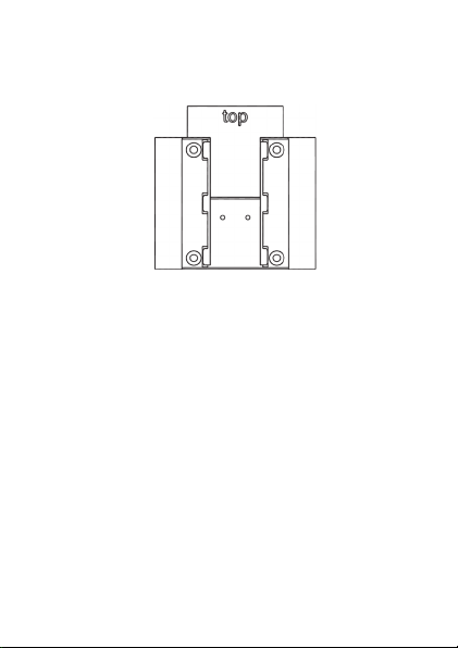
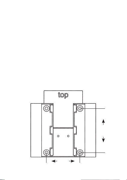
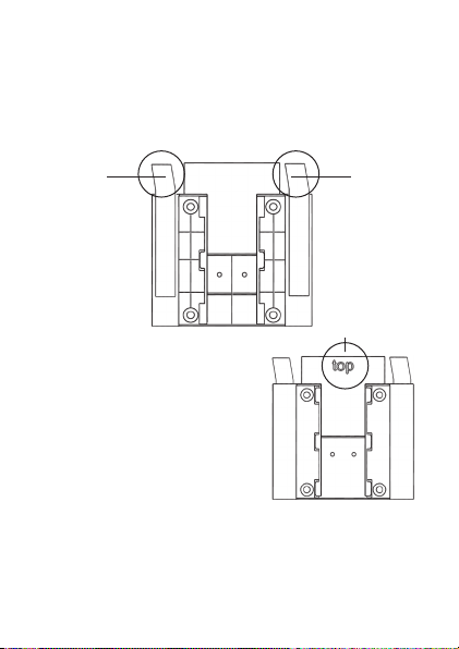
• Zuerst sind die vier Bohrlöcher (a) an
der Wand zu markieren. Wenn Sie die
Montageplatte dazu an die Wand halten,
muss die Aufschrift „top“ auf der sichtbaren
Seite oben stehen.
• Bohren Sie bei einer Steinwand vier
Löcher von 5 mm und verwenden Sie die
beiliegenden Dübel. Bei einer Holzwand
können 1,5 mm zum leichteren Eindrehen
der Schrauben vorgebohrt werden.
• Drehen Sie die Schrauben ein.
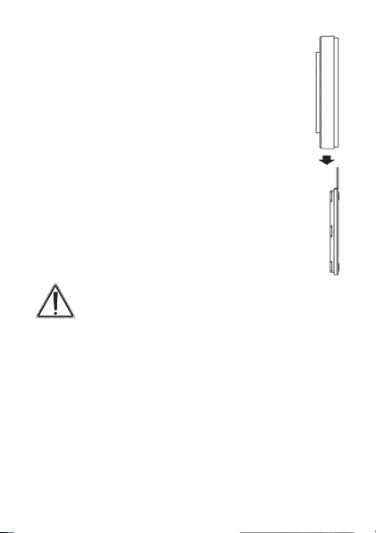
• Der Wandtaster ist danach von oben auf die
Halterung zu schieben.
Wenn Sie den Wandtaster über bereits installierte Taster, Schalter oder Steckdosen
anbringen möchten, beachten Sie bitte dringend, dass im Normalfall die Stromleitungen nach
oben führen. Es besteht die Gefahr eines elektrischen Schlages. In diesem Fall sollten Sie eine
Befestigung mit Klebestreifen wählen.
7.2 Montage mit Klebestreifen
Zum Befestigen mit Klebestreifen gehen Sie wie
folgt vor:
• Wählen Sie einen Ort zur Befestigung aus.
• Die Klebestreifen sind auf der Rückseite der
13
Montageplatte zu befestigen (nicht auf der Seite,
auf der das Wort „top“ steht). Ziehen Sie dazu auf
einer Seite der Klebestreifen den Schutzfilm ab.
Die Laschen der Klebestreifen müssen oben in den
ausgesparten Bereichen (b) überstehen.
b b
• Ziehen Sie die
c
Schutzfolie der zweiten
Klebestreifenseite ab.
• Nun können Sie die
Montageplatte des
Wandtasters am
gewünschten Ort ankleben.
Das Wort „top“ (c) muss im
angeklebten Zustand lesbar
sein. Drücken Sie die Wandhalterung für einen
kurzen Moment fest gegen die Wand.
• Der Wandtaster ist danach von oben auf die
Halterung aufzuschieben.
14
8. Inbetriebnahme
8.1 Batterien einlegen (wechseln)
Der Wandtaster wird mit 3 LR03 (Micro/AAA)
Batterien betrieben.
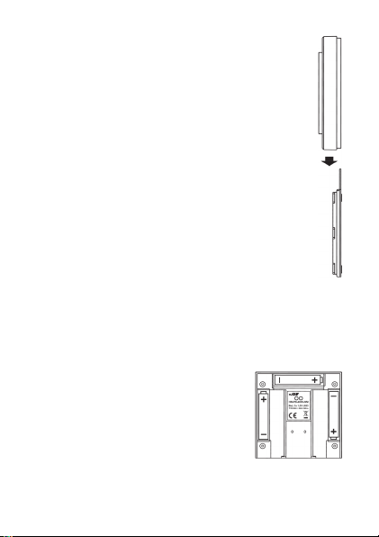
• Ziehen Sie den Wandtaster nach oben von
der Montageplatte ab.
• Auf der Rückseite des Wandtasters sind die
Batteriehalterungen zu sehen.
• Legen Sie 3 neue LR03-Batterien (Micro/
AAA) polungsrichtig in die Batteriefächer ein.
• Falls bereits montiert, ist der Wandtaster
danach von oben auf die Montageplatte
aufzuschieben.
Die Lebensdauer neuer Alkali-Batterien beträgt ca.
zwei Jahre. Die Batterielebensdauer ist von der Häufigkeit der Bedienung (bzw. der Display-Aktivierung)
abhängig.
Wenn die Batterien auszutauschen
sind, wird dies im Display signalisiert. Nach Aktivierung des Displays
wird eine entsprechende Meldung
kurz eingeblendet. Wird das Gerät
im Zusammenhang mit einer HomeMatic Zentrale betrieben, wird auch eine ServiceMeldung an die Zentrale geschickt.
15
Vorsicht! Explosionsgefahr bei unsachgemäßem Austausch der Batterien.
Normale Batterien dürfen niemals aufgeladen
werden. Es besteht Explosionsgefahr.
Batterien nicht ins Feuer werfen!
Batterien nicht kurzschließen!
Verbrauchte Batterien gehören nicht in
den Hausmüll! Entsorgen Sie diese in
Ihrer örtlichen Batteriesammelstelle!
8.2 Anlernen
Damit Funk-Komponenten miteinander kommunizieren können, müssen Sie aneinander angelernt sein.
Damit HomeMatic Aktoren mit dem Wandtaster geschaltet werden können, gehen Sie wie folgt vor:
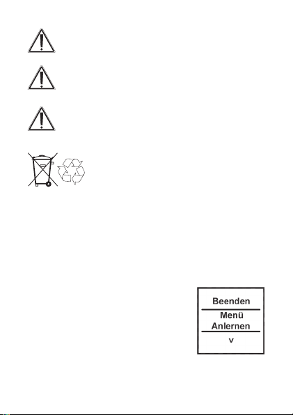
Öffnen Sie das Konfigurations-
•
Menü durch einen langen
Tastendruck nach links oder rechts
().
• Im Display wird die oberste Menü-
Ebene eingeblendet. Mit einem
Tastendruck nach links/rechts () können
die verschiedenen Punkte der Menü-Ebene
16
ausgewählt werden.
• Wählen Sie den Punkt „Menü, Anlernen“ mit einem
Tastendruck nach unten () aus.
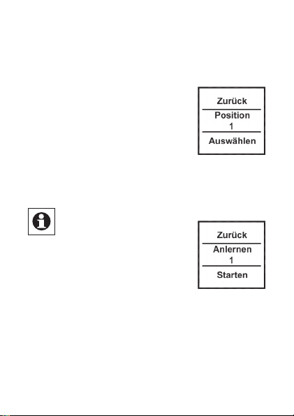
• In der nächsten Menü-Ebene
können Sie mit Tastendrücken
()
nach links/rechts
eine
Speicherposition (Kanal)
auswählen. Es wird zuerst die
nächst freie Position zur Auswahl
gestellt.
• Bestätigen Sie die Auswahl mit einem Tastendruck
nach unten ().
Zum Anlernen an eine Zentrale ist der Eintrag
„Zentrale“ auszuwählen
(Tastendruck
).
• Der Anlernvorgang kann nun mit
einem Tastendruck nach unten ()
aktiviert werden. Der Wandtaster
sucht dann für 20 Sekunden
nach einer anderen HomeMatic Komponente, die
ebenfalls im Anlernmodus ist.
Während dieser Zeit ist also auch das anzulernende
•
Gerät in den Anlernmodus zu versetzen.
17
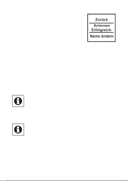
• Nach erfolgreichem
Anlernen können Name und
Raumbezeichnung geändert
werden.
• Nach dem Anlernen ist zunächst
„Position“ als Name hinterlegt und die zugehörige
Nummer als Raum (hier im Beispiel „1“).
• Mit Tastendrücken nach links/rechts () können
Sie zwischen „Name ändern“ und „Raum ändern“
wechseln.
• Bestätigen Sie die Auswahl mit einem Tastendruck
nach unten ().
Nach der Auswahl kann ein vorgegebener
Name oder Raum ausgewählt werden oder
Sie definieren diese frei. Für Details lesen Sie
bitte Abschnitt 8.3.
Der Wandtaster verfügt über 10 Kanäle, im
Folgenden auch Positionen genannt. An
jeden Kanal können bis zu 10 HomeMatic
Geräte angelernt werden. Sind mehrere Geräte an
einen Kanal angelernt, wird dies als Gruppe bezeichnet. Ein Schaltvorgang wird für alle Geräte der
Gruppe gleichzeitig ausgelöst.
18

8.3 Namen / Raum ändern
Für jedes am Wandtaster angelernte Gerät bzw. jeden Kanal kann ein Name (z.B. Licht) und ein Raum
(z.B. Wohnzimmer) hinterlegt werden. Sie können
aus einer Auswahl vorgegebener Bezeichnungen
wählen oder einen individuellen Namen mit maximal
12 Zeichen eingeben.
Die Änderung eines Namens oder einer Raumbezeichnung sind gleich und werden daher im Fol-
genden nur einmal exemplarisch erklärt.
• Öffnen Sie das Kongurations-
Menü durch einen langen
Tastendruck nach links oder rechts
().
• Im Display wird die oberste
Menü-Ebene eingeblendet. Mit
Tastendrücken nach links/rechts () ist der
Punkt „Menü, Kanäle“ auszuwählen.
• Mit einem Tastendruck nach unten () kommen
Sie in die nächste Menü-Ebene.
• In der nächsten Menü-Ebene
können Sie mit Tastendrücken
nach links/rechts () eine
Speicherposition (Kanal)
auswählen. Im Beispiel ist es das
19
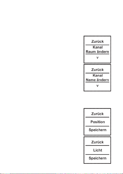
Gerät mit Namen „Position“ im Raum „1“.
• Bestätigen Sie die Auswahl mit einem Tastendruck
nach unten ().
• Danach stehen Ihnen neben
„Ablernen“ die Punkte „Name
ändern“ und „Raum ändern“ zur
Verfügung.
• Wählen Sie () den Punkt „Name
ändern“ oder „Raum ändern“ mit
einem Tastendruck nach unten
() aus.
• Im folgenden Beispiel ist der Punkt
„Name ändern“ ausgewählt. Das
Vorgehen bei der Änderung einer
Raum-Bezeichnung ist gleich.
• Mit Tastendrücken nach links/
rechts () können Sie die
verschiedenen vorgegebenen
Bezeich nungen durchgehen.
• Mit einem Tastendruck nach unten
() wählen Sie einen Namen aus
und speichern diesen sogleich.
• Im Beispiel rechts wurde die
Bezeichnung Licht ausgewählt.
20

• Sie haben zusätzlich die Möglichkeit einen freien
Namen zu hinterlegen bzw. einen vorgegebenen zu
ändern, dies ist fortfolgend erklärt.
Freie Namensvergabe/Editiermodus:
• Mit einem langen Tastendruck
(länger als 4 Sekunden) nach
links oder rechts () wird der
Editiermodus gestartet.
• Mit Tastendrücken nach links/
rechts () können Sie die 12
Ziffern einzeln anwählen. Mit
Tastendrücken nach oben/unten
() ändern Sie die jeweilige
Ziffer.
Es kann zwischen Groß-/
•
Kleinschreibung und Sonderzeichen gewechselt werden,
drücken Sie dazu den Taster lang nach oben/unten ().
• Über einen langen Tastendruck nach links oder
rechts () wird der Name gespeichert und der
Editiermodus verlassen.
• Im nebenstehenden Beispiel
wurde neben dem Namen auch die
Raumbezeichnung geändert.
21

•
Mit dem auf Position/Kanal 1 angelernten Aktor wird
somit das Deko-Licht im Wohnzimmer geschaltet.
8.4 Ablernen
Am Wandtaster angelernte Geräte können auch wieder abgelernt werden. Das Ablernen erfolgt je Kanal/
Position. Zum Ablernen von Geräten gehen Sie wie
folgt vor:
• Öffnen Sie das Kongurations-
Menü durch einen
langenTastendruck nach links oder
rechts ().
• Im Display wird die obersteMenü-
Ebene eingeblendet. Mit
Tastendrücken nach links/rechts () ist der
Punkt „Menü, Kanäle“ auszuwählen.
• Mit einem Tastendruck nach unten () kommen
Sie in die nächste Menü-Ebene.
• In der nächsten Menü-Ebene
können Sie mit Tastendrücken
nach links/rechts () eine
Speicherposition (Kanal)
auswählen. Im Beispiel wurde
22

das Gerät „Deko Licht“ im Raum „Wohnzimmer“
ausgewählt.
• Bestätigen Sie Ihre Auswahl mit einem
Tastendruck nach unten ().
• Wählen Sie anschließend mit
Tastendrücken nach links/rechts
() den Punkt „Ablernen“ aus.
• Bestätigen Sie die Auswahl mit
einem Tastendruck nach unten ().
• Danach erfolgt eine
Sicherheitsabfrage.
• Das Ablernen (Löschen) muss
bestätigt werden.
• Mit der Auswahl „Nein“ bzw.
einem Tastendruck nach oben ()
beenden Sie den Ablernvorgang.
• Mit „Ja“ bzw. einem langen Tastendruck (länger
als 4 Sekunden) nach unten () wird der
Ablernvorgang ausgeführt.
Wurden mehrere Geräte an einen Kanal bzw.
eine Position angelernt, werden diese ge-
meinsam abgelernt. Andere Kanäle/Positi-
onen bleiben unverändert bestehen.
23

8.5 Sprache auswählen
Im Wandtaster sind zur Bedienung und für Menüs
die Sprachen Deutsch und Englisch hinterlegt. Zum
ändern der Sprache gehen Sie wie folgt vor:
• Öffnen Sie das Kongurations-
Menü durch einen langen
Tastendruck nach links oder rechts
().
• Mit Tastendrücken nach links/
rechts () ist der Punkt „Menü,
Einstellung“ auszuwählen.
• Mit einem Tastendruck nach unten
() gelangen Sie in die nächste
Menü-Ebene.
• In der nächsten Menü-Ebene ist
mit Tastendrücken nach links/
rechts () der Punkt „Sprache“
auszuwählen.
• Bestätigen Sie die Auswahl mit
einem Tastendruck nach unten ().
• Im Punkt Sprache kann nun mit einem Tastendruck
nach links/rechts () die Sprache geändert
werden.
• Die angezeigte Sprache ändert sich gleichzeitig
24

im Display.
• Bestätigen Sie Ihre Auswahl mit „Speichern“ bzw.
„Save“ ().
• Zum Verlassen ohne zu speichern drücken Sie
„Zurück“ bzw. „Back“ ().
8.6 Werkseinstellungen wieder herstellen
Der Wandtaster kann in den Auslieferungszustand zurückgesetzt werden. Beim Herstellen
der Werkseinstellungen gehen alle gespeicherten
Einstellungen und Verknüpfungen verloren. Zum
Herstellen der Werkseinstellungen gehen Sie wie
folgt vor:
• Öffnen Sie das Kongurations-Menü
durch einen langen Tastendruck
nach links oder rechts ().
• Danach ist mit Tastendrücken
nach links/rechts () der Punkt
„Menü, Einstellung“ auszuwählen.
• Mit einem Tastendruck nach unten () gelangen
Sie in die nächste Menü-Ebene.
• In der nächsten Menü-Ebene ist mit Tastendrücken
nach links/rechts () der Punkt „Werkseinst.“
auszuwählen.
25

• Bestätigen Sie die Auswahl mit
einem Tastendruck nach unten ().
• Das Wiederherstellen der
Werkseinstellungen muss bestätigt
werden.
• Mit der Auswahl „Nein“ bzw.
einem Tastendruck nach oben ()
beenden Sie den Vorgang.
• Mit „Ja“ bzw. einem langen
Tastendruck (länger als
4 Sekunden) nach unten () werden die
Werkseinstellungen wieder hergestellt.
Beim Wiederherstellen der Werkseinstel-
lungen gehen alle Verknüpfungen mit ange-
lernten Geräten und vorgenommenen Einstel-
lungen unwiderruflich verloren.
8.7 Display-Standby Zeit einstellen
Das Display schaltet sich bei Inaktivität automatisch
aus, um die Lebensdauer der Batterien zu erhöhen. Diese Zeit ist auf 10 Sekunden voreingestellt.
Diese Einstellung kann in einem Bereich von 1 bis
99 Sekunden eingestellt werden. Zum Ändern der
Standby-Zeit gehen Sie wie folgt vor:
26

• Öffnen Sie das Kongurations-
Menü durch einen langen
Tastendruck nach links oder rechts
().
• Danach ist mit Tastendrücken nach
links/rechts () der Punkt „Menü,
Einstellung“ auszuwählen.
• Mit einem Tastendruck nach unten () gelangen
Sie in die nächste Menü-Ebene.
• In der nächsten Menü-Ebene ist
mit Tastendrücken nach links/
rechts () der Punkt „Standby“
auszuwählen.
Bestätigen Sie die Auswahl mit
•
einem Tastendruck nach unten ().
• Die Standby-Zeit kann mit
Tastendrücken nach links/rechts
() verändert werden. Durch
einen langen Tastendruck verstellt
sich die Zeit im 10-Sekundentakt.
• Mit der Auswahl „Zurück“ bzw.
einem Tastendruck nach oben (), beenden Sie
den Vorgang ohne zu speichern.
• Mit „Speichern“ bzw. einem Tastendruck nach
27

unten () wird die eingestellte Standby-Zeit
gespeichert.
9. Status Rückmeldungen
Der Wandtaster als HomeMatic-Komponente überträgt Daten mittels BidCoS-Protokoll. Dieses Bidirektionale Protokoll ermöglicht es, dass sendende
Geräte eine Rückmeldung vom empfangenden Gerät
erhalten.
Wird ein Schaltvorgang am Wandtaster durch einen
Tastendruck ausgelöst, wird dies im Display durch
eine orange Einfärbung der Schrift dargestellt. Nach
einer Rückmeldung vom empfangenden Gerät,
dass der Schaltvorgang ausgeführt wurde, wird
die Schrift grün dargestellt. Wenn der Empfänger
den Schaltvorgang nicht ausgeführt hat oder keine
Funkverbindung aufgebaut werden konnte, wird dies
durch eine rote Schrift angezeigt.
10. Geräte-Namen und
Schaltfunktionen
Jedem Gerät kann individuell ein Name zugewiesen
werden. Mit der Zuweisung eines Namens wird
gleichzeitig die Beschriftung für die Schaltfunkti-
28

onen (Tastendruck oben und unten) festgelegt. Die
folgende Tabelle gibt einen Überblick über die zum
Namen/Gerät zugehörigen Schaltfunktionen:
Gerät
Obere
Schaltfunktion
Untere
Schaltfunktion
Aktor An Aus
Dimmer An Aus
Fenster Öffnen Schließen
Gruppe An Aus
Jalousie Auf Zu
KeyMatic Entriegeln Verriegeln
Licht An Aus
Markise Auf Zu
Tür Entriegeln Verriegeln
Verschluss Entriegeln Verriegeln
WinMatic Öffnen Schließen
Bei Dimmern oder z.B. Markisen lassen sich über
einen langen Tastendruck Prozentwerte einstellen.
So kann ein Dimmer z.B. auf 60% hochgedimmt
werden. Diese Werte werden im Display kurzzeitig
anstelle des Raumes eingeblendet.
29

11. Funktionen mit Zentrale
Im Zusammenspiel mit einer HomeMatic Zentrale
sind noch weitere Funktion gegeben, so können
z.B. Programme über den Wandtaster gestartet
werden. Die Konfiguration muss dann über die
Konfigurationsoberfläche der Zentrale geschehen.
Über eine Zentrale können alle Namen frei vergeben
werden. Zudem könnten einem Tastenpaar auch
unterschiedliche Geräte oder Programme zugeordnet werden (z.B. oben „Licht an“, unten „Programm
starten“). Dadurch erhöht sich die Anzahl anlernbarer Komponenten auf 200.
Das Konfigurations-Menü ist nur noch mit zwei
Funktionen belegt:
(1) Zentrale: Mit der Funktion „Sync.“ werden die
Konfigurationsdaten von einer Zentrale abgefragt.
Haben Sie Änderungen an der Konfiguration über
die Zentrale vorgenommen, müssen diese durch
eine manuelle Betätigung der „Sync.“ Funktion zum
Wandtaster übertragen werden.
(2) Einstellung, Werkseinstellungen: Die Werkseinstellungen können weiterhin wie unter Abschnitt 8.6
beschrieben hergestellt werden.
30

Nachdem der Wandtaster an eine Zentrale
angelernt wurde, können Geräte nicht mehr
direkt am Wandtaster ab- oder angelernt
werden. Dies muss über die Bedienoberflä-
che der Zentrale geschehen.
12. Wartung und Reinigung
Neben einem Batteriewechsel ist das Produkt ist
wartungsfrei. Überlassen Sie eine Reparatur einer
Fachkraft.
13. Technische Eigenschaften
Display: OLED Vollgrafik-Display
Freifeldreichweite: bis zu 100 m
Spannungsversorgung: 3 x LR03 / Micro, AAA
Schutzart: IP 20
Gehäusefarbe: RAL 9010 Reinweiß mit
schwarz umrandeter
Sichtscheibe
Abmessungen (B x H x T): 83 x 83 x 18 mm
Batterielebensdauer: ca. 2 Jahre (bei bis zu
10 Betätigungen je Tag)
Maximale Anzahl
anlernbarer Geräte: 100 ohne Zentrale
200 mit Zentrale
31

Technische Änderungen, die zur Verbesserung dienen, sind vorbehalten.
Entsorgungshinweis
Gerät nicht im Hausmüll entsorgen! Elektro-
nische Geräte sind entsprechend der Richt-
linie über Elektro- und Elektronik-Altgeräte
über die örtlichen Sammelstellen für Elektro-
nik-Altgeräte zu entsorgen.
Das CE-Zeichen ist ein Freiverkehrszeichen,
das sich ausschließlich an die Behörden
wendet und keine Zusicherung von Eigen-
schaften beinhaltet.
32

1st English edition 02/2010
Documentation © 2009 eQ-3 Ltd., Hong Kong
All rights reserved. This manual may not be
reproduced in any format, either in whole or in part,
nor may it be duplicated or edited by electronic,
mechanical or chemical means, without the written
consent of the publisher. Typographical and printing
errors cannot be excluded. However, the information
contained in this manual is reviewed on a regular
basis and any necessary corrections will be
implemented in the next edition. We accept no
liability for technical or typographical errors or the
consequences thereof.
All trademarks and industrial property rights are
acknowledged.
Printed in Hong Kong.
Changes may be made without prior notice as a
result of technical advances.
90218/V 1.2
33

Contents
1 Information about this manual ...........35
2 Hazard information ....................35
3 Function............................. 36
3.1 General function ...................... 36
3.2 Overview ............................36
3.3 Scope of supply ......................37
4 Display, operation, menu ...............38
4.1 Display areas.........................38
4.2 General operation and menu ............39
5 General system information
about HomeMatic .....................41
6 General information about radio operation . 42
7 Mounting ............................43
7.1 Mounting with screws..................43
7.2 Mounting with adhesive strips ...........44
8 Start-up ............................. 46
8.1 Inserting (replacing) batteries............46
8.2 Teaching-in ..........................47
8.3 Changing a name/room ................50
8.4 Teaching-out ......................... 53
8.5 Selecting the language .................55
8.6 Restoring the factory settings ...........56
8.7 Setting the display standby time ......... 57
9 Feedback statuses .................... 59
10 Device names and switching functions ....59
11 Functions with a central control unit ...... 61
12 Maintenance and cleaning ..............62
13 Technical characteristics ...............63
34

1 Information about this manual
Read this manual carefully before starting to use
your HomeMatic components. Keep the manual so
you can refer to it at a later date should you need to.
If you hand over the device to other persons for use,
please hand over the operating manual as well.
Attention!
This indicates a hazard.
Note. This section contains important
additional information.
2 Hazard information
The device may only be operated indoors and must
be protected from the effects of damp and dust, as
well as solar or other methods of heat radiation.
Using this device for any purpose other than that
described in this operating manual does not fall
within the scope of intended use and shall invalidate
any warranty or liability.
Do not open the device: it does not contain
any components that need to be serviced by
the user. In the event of an error, please
return the device to our service department.
35

3 Function
3.1 General function
A wall-mounting pushbutton is used to activate
the receivers that have been taught-in to it. It also
features a display that is used to show the name of
a taught-in device and the room where it is located,
and to output status messages relating to radio
commands that have been issued.
The wall-mounting pushbutton has 10 channels;
between 1 and 10 components can be taught-in to
each of these channels. This means that multiple
actions can be performed at just one touch of a
single button.
Basic functions and the names of actuators/rooms
can be set locally on the wall-mounting pushbutton
itself. Since this is a surface-mounting device, it can
be quite easily retrofitted anywhere in the home.
3.2 Overview
The wall-mounting pushbutton
consists of two parts:
A
36

B
(A) Wall-mounting pushbutton
(B) Mounting plate
3.3 Scope of supply
• Wall-mounting pushbutton
• Mounting plate
• Adhesive strips for wall mounting
• 3x LR03 batteries (micro/AAA)
• 2x wood screws 3.0 x 30 mm
• 2x plugs 5 mm
37

4. Display, operation, menu
4.1 Display areas
a
b
c
The display is divided into 3 areas:
The central area (b) provides information about the
actuator and the room. In the example above, an
actuator has been called “Light” and the room has
been named “Living room”. These names can be
defined in accordance with individual requirements
(refer to Section 8.3).
The available switching options are shown in the
upper (a) and lower (c) areas. An actuator to be
used for controlling lights would have the switching
options “On” and “Off” assigned to it. If KeyMatic
were to be selected as the actuator, the switching
options “Unlock” and “Lock” would be shown
instead, for example (refer also to Section 10).
38

Switching operations are confirmed on the display. If an action (such as switching on the light) is
performed via the wall-mounting pushbutton, the
display text will initially be orange to indicate that
the associated command is being transmitted. If
the wall-mounting pushbutton receives feedback
from the actuator confirming that the light has been
switched on successfully, the text will immediately
change to green. If the light could not be switched
on for any reason, this will be indicated by the text
changing to red.
4.2 General operation and menu
The rocker on the wall-mounting pushbutton can be
pressed in four different directions. A general distinction is also made between pressing and releasing
the button (button pressed for under 4 seconds) and
pressing and holding down the button (button pressed
for more than 4 seconds). Press the left (a) or right (b)
of the button to select one of the various taught-in
devices or channels. Up to 10 channels (positions 1
to 10) can be assigned. Pressing the button at the top
(c) or bottom (d) triggers an action. Usually the top (c)
switches a device on and the bottom (d) switches it
off. Pressing the button and holding it down can trigger an additional function for some actuators: with a
dimmer, for example, pressing the button at the top
39

or bottom and holding it down will dim or brighten
the light by degrees. The configuration menu can be
opened by pressing the button on the left (a) or right
(b) and holding it down. For details on the configuration menu, please refer to Section 8.
c
a b
d
Press button
and release
a
Select device/
b
channel
Select device/
channel
cTrigger switching
operation
dTrigger switching
operation
40
Press button
and hold down
Open menu
Open menu
Trigger switching
operation
Trigger switching
operation

Display standby: The display switches to
standby mode after approximately 10 sec-
onds to maximise battery life. Pressing any
one of the four sides of the pushbutton rocker will
reactivate the display. On reactivation, the first channel or position 1 is displayed by default. The (standby) time is set as described in Section 8.7.
Menu time-out: The configuration menu is
opened by pressing the button and holding it
down (for longer than 4 seconds). After 60 seconds of inactivity the menu closes automatically and the
wall-mounting pushbutton returns to operation mode.
5. General information
about the HomeMatic system
This device is part of the HomeMatic home control
system and works with the bi-directional BidCoS
wireless protocol. All devices are delivered in a standard configuration. The functionality of the device can
also be configured with a programming device and
software. The additional functions that can be made
available in this way and the supplementary functions
provided by the HomeMatic system when it is combined with other components are described in the
HomeMatic System Manual.
®
41

You can find the latest versions of all technical
documents and the latest updates at
www.HomeMatic.com.
6. General information about
radio operation
Radio transmission is performed on a non-exclusive
transmission path, which means that there is a possibility of interference occurring. Interference can
also be caused by switching operations, electrical
motors or defective electrical devices.
The range of transmission within buildings
can differ greatly from that available in the
open air. Besides the transmitting power and
the reception characteristics of the receiver, environmental factors such as humidity in the vicinity have
an important role to play, as do on-site structural/
screening conditions.
eQ-3 Entwicklung GmbH hereby declares that this
device complies with the essential requirements and
other relevant regulations of Directive 1999/5/EC.
You can find the full declaration of conformity at
www.HomeMatic.com.
42

7. Mounting
The wall-mounting pushbutton is a surfacemounting device, so it can be retrofitted anywhere in
the home. You can choose from two different types
of mounting: mounting with screws (7.1) or mounting
with adhesive strips (7.2).
7.1 Mounting with screws
To mount the device on a wall, proceed as follows:
• Select a suitable mounting location.
• Make sure that no electricity or similar lines run in
the wall at this location.
a
52.5
a
40.0
a a
43

• First of all, mark four bore hole positions (a)
on the wall. When you hold the mounting
plate against the wall, the inscription “top”
must be visible at the top edge.
• If you are working with a stone wall, drill four
5 mm holes and insert the plugs supplied. If
you are working with a wooden wall, you can
pre-drill 1.5 mm holes to make the screws
easier to insert.
• Screw the screws in.
• Then slide the wall-mounting pushbutton
onto the holder from above.
If you want to install the wall-mounting
pushbutton above other pushbuttons,
switches or sockets that are already in place,
you must bear in mind the fact that current lines
usually run upwards. This means there is a risk of
electric shock. In such cases you should attach the
wall-mounting pushbutton with adhesive strips.
7.2 Mounting with adhesive strips
To attach the wall-mounting pushbutton with adhesive strips, proceed as follows:
• Select a mounting location.
• Attach the adhesive strips to the rear of the
mounting plate (not on the side where the word
44

“top” is printed). To attach the adhesive strips,
remove the protective film from one side. The
ends of the adhesive strips must protrude from the
cut-out areas (b) at the top of the mounting plate.
b b
• Pull the protective lm off the other
c
side of the adhesive strips.
• You can now stick the
mounting plate for the wallmounting pushbutton onto
the wall at the required site.
When the plate is stuck in
place, the word “top” (c)
must be visible. Briefly press
the wall mount firmly against
the wall.
• Then slide the wall-mounting pushbutton onto the
holder from above.
45

8. Start-up
8.1 Inserting (replacing) batteries
The wall-mounting pushbutton runs on
3x LR03 (micro/AAA) batteries.
• Slide the wall-mounting pushbutton up and
off the mounting plate.
• You will see the battery holders on the rear
of the wall-mounting pushbutton.
• Insert 3 new LR03 (micro/AAA) batteries in
the battery compartments (making sure that
you insert them the right way round).
• If you have already attached the mounting
plate to the wall, slide the wall-mounting
pushbutton onto it from above.
The service life of new alkaline batteries is approximately two years. The battery life will depend on
how frequently operations are carried out (or how
often the display is activated).
The display will indicate when it is
time to replace the batteries. When
the display has been activated, a corresponding message will briefly appear. If the device is being operated in
conjunction with a HomeMatic central
control unit, a service message is sent to the CCU too.
46

Caution! There is a risk of explosion if the
batteries are not replaced correctly.
Never recharge standard batteries.
Doing so will present a risk of explosion.
Do not throw batteries into a fire.
Do not short-circuit batteries.
Used batteries should not be disposed
of with regular domestic waste. Instead, take them to your local battery
disposal point.
8.2 Teaching-in
In order to enable communication between radio
components, the devices have to be taught-in to
one another. If you want to use the wall-mounting
pushbutton to switch HomeMatic actuators,
proceed as follows:
• Open the conguration menu by
pressing and holding down the
button on the left or right ().
• The top menu level appears on
the display. Press the button on
47

the left/right () to browse through the different
items in that menu level.
• Select the “teach-in” item menu by pressing the
button at the bottom () .
• In the next menu level you can
select a storage position (channel)
by pressing the button on the left/
right (). The next available
position is displayed for selection
first.
• Conrm your selection by pressing the button at
the bottom ().
In order to teach in at a central control unit,
select the “Central control
unit” entry (press button ).
• You can now activate the teach-in
procedure by pressing the button
at the bottom (). For the next
20 seconds the wall-mounting
pushbutton will search for another HomeMatic
component that is also in teach-in mode.
• This means that the device to be taught-in needs
to be switched to teach-in mode during this time
too.
48

• Once teaching-in has been
completed successfully,
the device and room names
can be changed.
• After teaching-in has been
completed, “Position” is initially
stored as the name and the associated number is
stored for the room (in this example, “1”).
• Press the button on the left/right () to toggle
between “Change name” and “Change room”.
• Conrm your selection by pressing the button at
the bottom ().
Once you have made your selection you can
either choose a preset name or room, or
define your own. For details on this, please
refer to Section 8.3.
The wall-mounting pushbutton features
10 channels, also referred to as “positions”
in the following. Up to 10 HomeMatic devices
can be taught-in to each channel. If several devices
have been taught-in to one channel, they are
referred to as a group. A switching operation will be
triggered for all the devices in the group
simultaneously.
49

8.3 Changing a name/room
A name (e.g. Light) and a room (e.g. Living room)
can be stored for every device taught-in to the wallmounting pushbutton or for every channel.
You can choose from a selection of preset names
or enter a customised name with a maximum of 12
characters.
The name of a device and that of a room are
changed in the same way, so just one example is
given below to explain both processes.
• Open the conguration menu by
pressing and holding down the
button on the left or right ().
• The top menu level appears on the
display. Press the button on the
left/right () to select the menu
item “Channels”.
• Press the button at the bottom () to access the
next menu level.
• In the next menu level you can
select a storage position (channel)
by pressing the button on the left/
right (). This example refers
to the device called “Position” in
room “1”.
50

• Conrm your selection by pressing the button at
the bottom ().
• Now you can select either “Teach-
out” or the “Change name” or
“Change room” items.
• Select () the “Change name” or
“Change room” item by pressing
the button at the bottom () .
• In the example below, the “Change
name” item has been selected. The
procedure for changing the name
of a room is the same.
• Press the button on the left/right
() to browse through the
different preset names.
• Press the button at the
bottom () to select a name and
save it at the same time.
• In the example on the right, the
name “Light” has been selected.
• You can also enter and save a
customised name or modify a
preset name; this process is
explained below.
51

Assigning customised names/Edit mode:
• Launch edit mode by pressing
and holding down the button on
the left or right () for more than
4 seconds.
• Press the button on the left/
right () to select the 12 digits
individually. Press the button at the
top/bottom () to change the
corresponding digit.
• You can toggle between upper/
lower case and special characters
by pressing and holding down the pushbutton at
the top/bottom ().
• Press and hold down the button on the left or right
() to save the name and exit edit mode.
• In the example on the right,
both the device and room
names have been changed.
• The actuator taught-in to
position/channel 1 controls
the decorative light in the living
room.
52

8.4 Teaching-out
Devices that have been taught-in to the wallmounting pushbutton can also be taught-out again.
Teaching-out is performed separately for each
channel/position. To teach-out devices, proceed as
follows:
• Open the conguration menu by
pressing and holding down the
button on the left or right ().
• The top menu level appears on the
display. Press the button on the
left/right () to select the
“Channels menu” item.
• Press the button at the bottom
() to access the next menu level.
• In the next menu level you can
select a storage position (channel)
by pressing the button on the left/
right (). In this example, the
“Decorative light” device in room
“Living room” has been selected.
• Conrm your selection by pressing
the button at the bottom ().
53

• Now press the button on the left/right () to
select the “Teach-out” item.
• Conrm your selection by pressing
the button at the bottom ().
• A conrmation prompt will then
appear.
• The teach-out (delete) procedure
needs to be confirmed.
• Select “No” or press the button at
the top () to end the teach-out
procedure.
• Select “Yes” or press and hold
down the button at the bottom ()
for more than 4 seconds to perform the teach-out
procedure.
If several devices have been taught-in to one
channel or position, they are all taught-out
together. Other channels/positions remain
unaffected by this teach-out procedure.
54

8.5 Selecting the language
The languages English and German are stored in the
wall-mounting pushbutton for the purposes of operation and menu display. To change the language,
proceed as follows:
• Open the conguration menu by
pressing and holding down the
button on the left or right ().
• Press the button on the left/right
() to select the menu item
“Settings”.
• Press the button at the bottom ()
to access the next menu level.
• In the next menu level select the
“Language” item by pressing the
button on the left/right ().
• Conrm your selection by pressing
the button at the bottom ().
• Under the “Language” menu item
you can now change the language
by pressing the button on the
left/right ().
• The display language changes in
real time with the language setting.
55

• Conrm your selection by pressing “Save” ().
• To exit without saving your changes, press
“Back” ().
8.6 Restoring the factory settings
The wall-mounting pushbutton can be reset to its
initial state. When the factory settings are restored,
all saved settings and links are lost. To restore the
factory settings, proceed as follows:
• Open the conguration menu by
pressing and holding down the
button on the left or right ().
• Then press the button on the left/
right () to select the menu item
“Settings”.
• Press the button at the bottom () to access the
next menu level.
• In the next menu level select the “Factory set.”
item by pressing the button on the left/right ().
56

• Conrm your selection by pressing
the button at the bottom ().
• You must conrm that you want to
restore the factory settings.
• Select “No” or press the button at
the top () to end the procedure.
• Select “Yes” or press and hold
down the button at the bottom ()
for more than 4 seconds to restore
the factory settings.
When the factory settings are restored, all
links to taught-in devices and all settings you
have made are lost and cannot be retrieved.
8.7 Setting the display standby time
After a period of inactivity the display switches off
automatically in order to maximise battery life. This
time period is preset to 10 seconds. This setting can
be adjusted within a range from 1 to 99 seconds. To
change the standby time, proceed as follows:
57

• Open the conguration menu by
pressing and holding down the
button on the left or right ().
• Then press the button on the left/
right () to select the “Settings
menu” item.
• Press the button at the bottom ()
to access the next menu level.
• In the next menu level select the
“Standby” item by pressing the
button on the left/right ().
• Conrm your selection by pressing
the button at the bottom ().
• You can change the standby time
by pressing the button on the left/
right (). Press the button and
hold it down to change the time in
increments of 10 seconds.
• Select “Back” or press the button
at the top () to end the procedure without saving
your changes.
• Select “Save” or press the button at the bottom
() to save the standby time you have just set.
58

9. Feedback statuses
As a HomeMatic component, the wall-mounting
pushbutton transmits data via the BidCoS protocol.
This bi-directional protocol allows transmitting
devices to receive feedback from receiving devices.
If the wall-mounting pushbutton is pressed to
trigger a switching operation, this is indicated on the
display by the text turning orange. Once the
receiving device has issued feedback confirming
that the switching operation has been performed,
the text changes to green. If the receiver has not
carried out the switching operation or if no wireless
connection could be established, this is indicated by
the text turning red.
10. Device names and switching
functions
A name can be assigned to each individual device.
The designations of the switching functions (when
the button is pressed at the top or the bottom) are
defined when the name is assigned.
59

The table below provides an overview of which
switching functions belong to which name/device:
Device
Top switching
function
Bottom switching
function
Actuator On Off
Dimmer On Off
Window Open Close
Group On Off
Blinds
Open Close
KeyMatic Unlock Lock
Light On Off
Canopy Open Close
Door Unlock Lock
Lock Unlock Lock
WinMatic Open Close
For dimmers or canopies, for example, you can set
percentage values by pressing the button and
holding it down. This means that a dimmer can be
made brighter until it reaches 60% of its full
brightness, for example. These values appear on the
display briefly, in place of the room data.
60

11. Functions with a
central control unit
Even more functions are available if you use the
wall-mounting pushbutton in conjunction with a
HomeMatic central control unit, for example you
can start programs from the device. In such cases,
the configuration settings must be made via the
configuration interface of the central control unit.
All names can be freely assigned by means of a
central control unit. In addition, different devices or
programs can be allocated to a pair of buttons (e.g.
“Light on” at the top, “Start program” at the bottom).
This increases the number of components that can
be taught-in to 200.
However, the configuration menu still only has two
functions assigned to it:
(1) Central control unit: The “Sync.” function queries
configuration data from a central control unit. If you
have made changes to the configuration on the
central control unit, you will need to transfer them
to the wall-mounting pushbutton by activating the
“Sync.” function manually.
(2) Settings, factory settings: The factory settings
can still be restored as described in Section 8.6.
61

Once the wall-mounting pushbutton has been
taught-in to a central control unit, it will no
longer be possible to teach devices in to or
out from the wall-mounting pushbutton directly. This must be done via the central control
unit’s user interface.
12. Maintenance and cleaning
Apart from having to replace the batteries, this
product is maintenance-free. Enlist the help of an
expert to carry out any repairs.
62

13. Technical characteristics
Open air range: Up to 100 m
Display: OLED fully graphical
Power supply: 3x LR03/micro, AAA
Degree of protection: IP 20
Housing colour: RAL 9010 pure white with
Dimensions (W x H x D): 83 x 83 x 18 mm
Battery life: Approx. 2 years (at up to
Maximum number of 100 without a central
devices that can control unit
be taught-in: 200 with a central control
We reserve the right to make any technical changes
that constitute an improvement to the device.
display
a window surrounded by
a black border
10 operations per day)
unit
63

Instructions for disposal
Do not dispose of the device with regular
domestic waste. Electronic equipment must
be disposed of at local collection points for
waste electronic equipment in compliance
with the Waste Electrical and Electronic
Equipment Directive.
The CE Marking is simply an official symbol
relating to the free movement of a product; it
does not warrant a product’s characteristics.
eQ-3 AG
Maiburger Straße 29
D-26789 Leer
www.eQ-3.com
64
 Loading...