

Homematic HM-PB-2-WM55-2 Operating Manual

Installation and Operating Manual p. 23
Radio push button 2 channel:
HM-PB-2-WM55-2

1. English edition 10/2013
Documentation © 2013 eQ-3 Ltd., Hong Kong
All rights reserved. No parts of this manual may be
reproduced or processed in any form using electronic,
mechanical or chemical processes in part or in full
without the prior explicit written permission of the
publisher.
It is quite possible that this manual has printing
errors or defects. The details provided in this manual
are checked regularly and corrections are done in the
next edition. We do not assume any liability for technical or printing errors.
All registered trade marks and copyrights are
acknowledged.
Printed in Hong Kong
We reserve the right to make changes due to technical
advancements without prior notice.
131782 / V 1.0
23

Table of Contents
1 Information concerning these instructions ...25
2 Hazard information.....................25
3 Function . . . . . . . . . . . . . . . . . . . . . . . . . . . . . 26
4 General system information on HomeMatic .. 29
5 General information on radio operation .....29
6 Installation ...........................30
6.1 Scope of delivery ......................30
6.2 Adhesive strip mounting.................31
6.3 Screw mounting . . . . . . . . . . . . . . . . . . . . . . . 32
6.4 Installation in multiple combinations........ 33
7 Start up.............................. 34
7.1 Inserting (changing) batteries............. 34
7.2 Teaching-in...........................35
7.3 LED ashing sequences and transmission
behaviour . . . . . . . . . . . . . . . . . . . . . . . . . . . . 39
7.4 Resetting to factory status ...............40
8 Maintenance and cleaning ...............41
9 Technical specications .................42
24
1 Information concerning these
instructions
Read these instructions carefully before beginning
operation with your HomeMatic components. Keep
the instructions handy for later consultation!
Please hand-over the operating manual as well
when you hand-over the device to other persons
for use.
Symbols used:
Note! This indicates a hazard.
Note! This section contains additional
important information!
2 Hazard information
This device is to be operated indoors only and
keep away from the inuences of humidity,
dust and sunshine or other radiating heat
sources.
25
Using the push button for any purpose other
than that described in this operating manual
does not fall within the scope of intended use
and shall invalidate any warranty or liability.
This also applies to any conversion or
modication work. This device is intended for
private use only.
Do not open the device. It does not contain
any parts to be maintained by the user. If an
error occurs, please send back the device to
the customer service.
3 Function
HomeMatic push buttons are used to control the receivers that they are taught to work with. A single button
can be taught to work with one or more components
and address them all simultaneously. That means that
pressing a single button can execute many different
tasks.
The HomeMatic push button is battery-operated. As
such it is highly exible where mounting and selecting
a mounting location are concerned.
26

The HomeMatic push button is mounted and removed
very easily using screws or adhesive strips. It is compatible with a number of different surfaces including
furniture, brick walls, tiles or glass. Holes or slits do not
have to be chiselled out of brick walls. The frame supplied with the device can be used for wall mounting.
It is also possible to integrate the HomeMatic push
button into existing
switches (see sec. 6.4).
27
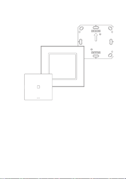
A
B
C
(A) Mounting plate
(B) Attachment frame
(C) Electronic unit/rocker button
28
 Loading...