


Installations- und
Bedienungsanleitung (S. 2)
Installation and
operating manual (p. 22)
Funk-Schaltaktor, 4-fach
Hutschienenmontage:
Radio-controlled switch actuator
4-channel, for mounting on DIN rails:
HM-LC-Sw4-DR

1. Ausgabe Deutsch 08/2010
Dokumentation © 2010 eQ-3 Ltd., Hong Kong
Alle Rechte vorbehalten. Ohne schriftliche
Zustimmung des Herausgebers darf dieses
Handbuch auch nicht auszugsweise in irgendeiner
Form reproduziert werden oder unter Verwendung
elektronischer, mechanischer oder chemischer
Verfahren vervielfältigt oder verarbeitet werden.
Es ist möglich, dass das vorliegende Handbuch
noch drucktechnische Mängel oder Druckfehler
aufweist. Die Angaben in diesem Handbuch werden
jedoch regelmäßig überprüft und Korrekturen in
der nächsten Ausgabe vorgenommen. Für Fehler
technischer oder drucktechnischer Art und ihre
Folgen übernehmen wir keine Haftung.
Alle Warenzeichen und Schutzrechte werden
anerkannt.
Printed in Hong Kong
Änderungen im Sinne des technischen Fortschritts
können ohne Vorankündigung vorgenommen
werden.
91751 / V 1.1
2

Inhaltsverzeichnis
1 Hinweise zu dieser Anleitung .............4
2 Gefahrenhinweise ......................4
3 Funktion..............................7
4 Allgemeine Systeminformation zu
HomeMatic ...........................9
5 Allgemeine Hinweise zum Funkbetrieb .....9
6 Installation ...........................11
7 Inbetriebnahme .......................14
7.1 Einfache Bedienfunktionen mit integrierten
Tastern .............................. 14
7.2 Anlernen.............................15
8 Bedienung ...........................16
9 Zurücksetzen in den Auslieferungszustand. 16
10 Rückmeldungen der Geräte-LED .........17
10.1 Blinkcodes........................... 17
10.2 Anzeige des Betriebszustandes..........17
11 Verhalten nach Spannungswiederkehr.....18
12 Wartung und Reinigung ................18
13 Technische Daten ..................... 19
3
1 Hinweise zu dieser Anleitung
Lesen Sie diese Anleitung sorgfältig, bevor Sie ihre
HomeMatic-Komponenten in Betrieb nehmen.
Bewahren Sie die Anleitung zum späteren
Nachschlagen auf!
Wenn Sie das Gerät anderen Personen zur
Nutzung überlassen, übergeben Sie auch diese
Bedienungsanleitung.
Achtung! Hier wird auf eine Gefahr
hingewiesen.
Hinweis. Dieser Abschnitt enthält zusätzliche
wichtige Informationen!
2 Gefahrenhinweise
Der beschriebene Aktor ist Teil einer
Gebäudeinstallation. Bei der Planung und
Errichtung von Elektrischen Anlagen sind
die einschlägigen Normen und Richtlinien
des Landes zu beachten, in dem die Anlage
installiert wird.
4

Der Betrieb des Gerätes ist ausschließlich am
230V/50Hz-Wechselspannungsnetz zulässig.
Arbeiten am 230V-Netz dürfen nur von einer ElektroFachkraft (nach VDE 0100) erfolgen. Dabei sind
die geltenden Unfallverhütungsvorschriften zu
beachten.
Zur Vermeidung eines elektrischen Schlages vor
Arbeiten am Gerät Netzspannung freischalten
(Sicherungsautomat abschalten). Bei Nichtbeachtung der Installationshinweise können ein Brand
oder andere Gefahren entstehen.
Betreiben Sie das Gerät nur in Innenräumen und
vermeiden Sie den Einfluss von Feuchtigkeit, Staub
sowie Sonnen- oder andere Wärmebestrahlung.
Jeder andere Einsatz als in dieser Bedienungsanleitung beschrieben ist nicht bestimmungsgemäß
und führt zu Garantie- und Haftungsausschluss.
Belasten Sie die Geräte nur bis zur angegebenen
Leistungsgrenze. Eine Überlastung kann zur
Zerstörung des Gerätes, zu einem Brand oder
elektrischen Unfall führen.
Das Gerät ist nicht zum Freischalten
geeignet.
5
Öffnen Sie das Gerät nicht, es enthält keine
durch den Anwender zu wartenden Teile. Das
Öffnen des Gerätes birgt die Gefahr eines
Stromschlages. Im Fehlerfall schicken Sie
das Gerät an den Service.
Beachten Sie beim Anschluss an die
Geräteklemmen die hierfür zulässigen
Leitungen und Leitungsquerschnitte.
Beachten Sie vor Anschluss eines
Verbrauchers unbedingt die technischen
Daten, insbesondere die maximal zulässige
Schaltleistung der Relais und Art des
anzuschließenden Verbrauchers! Alle
Lastangaben beziehen sich auf ohmsche
Lasten!
Beachten Sie die Installationsvorschriften für
Installationen in Verteilersystemen.
6

3 Funktion
Der Aktor schaltet bis zu 4 angeschlossene
Verbraucher mit einer Gesamt-Schaltleistung von
5750 VA (230 V/25 A) bzw. 3680 VA (230 V/16 A) je
Kanal aufgrund von empfangenen Funkbefehlen.
Befehle werden ausgesandt durch Betätigung
von Tastern, Fernbedienungen oder über eine
Softwareoberfläche. Zusätzlich ist es möglich,
Aktoren über angelernte Sensoren anzusteuern. Die
Sensoren senden (wie ein Taster) beim Eintreten
eines Ereignisses einen Befehl. Genaueres dazu
ist der Anleitung des entsprechenden Sensors zu
entnehmen.
Die Montage erfolgt auf einer Standard-Hutschiene
innerhalb von Verteilungen.
7
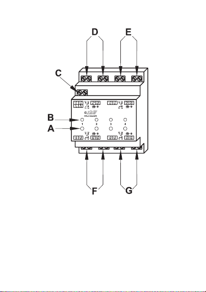
(A) Kanal-Taste Kanal 1 ... 4
(B) Kanal-LED Kanal 1 ... 4
(C) Spannungsversorgung 230 V
(D) Schaltkanal 1
(E) Schaltkanal 2
(F) Schaltkanal 3
(G) Schaltkanal 4
8

4 Allgemeine Systeminformation
zu HomeMatic
Dieses Gerät ist Teil des HomeMaticHaussteuersystems und arbeitet mit dem
bidirektionalen BidCoS
Alle Geräte werden mit einer Standardkonfiguration
ausgeliefert. Darüber hinaus ist die Funktion
des Gerätes über ein Programmiergerät und
Software konfigurierbar. Welcher weitergehende
Funktionsumfang sich damit ergibt, und welche
Zusatzfunktionen sich im HomeMatic-System
im Zusammenspiel mit weiteren Komponenten
ergeben, entnehmen Sie bitte dem HomeMaticSystemhandbuch.
Alle technischen Dokumente und Updates finden Sie
stets aktuell unter www.HomeMatic.com.
®
-Funkprotokoll.
5 Allgemeine Hinweise zum
Funkbetrieb
Die Funk-Übertragung wird auf einem nicht
exklusiven Übertragungsweg realisiert weshalb
Störungen nicht ausgeschlossen werden können.
9

Weitere Störeinflüsse können hervorgerufen werden
durch Schaltvorgänge, Elektromotoren oder defekte
Elektrogeräte.
Die Reichweite in Gebäuden kann
stark von der im Freifeld abweichen.
Außer der Sendeleistung und den
Empfangseigenschaften der Empfänger
spielen Umwelteinflüsse wie Luftfeuchtigkeit
neben baulichen Gegebenheiten vor Ort eine
wichtige Rolle.
Hiermit erklärt die eQ-3 Entwicklung GmbH, dass
sich dieses Gerät in Übereinstimmung mit den
grundlegenden Anforderungen und den anderen
relevanten Vorschriften der Richtlinie 1999/5/EG
befindet.
Die vollständige Konformitätserklärung finden Sie
unter www.HomeMatic.com.
10
6 Installation
Beachten Sie die Installationsvorschriften für
Installationen in Verteilersystemen.
Setzen Sie das Schaltmodul auf die Hutschiene auf
und verriegeln Sie es.
Achten Sie dabei darauf, dass die Rastfeder
komplett einrastet und das Gerät fest auf der
Schiene sitzt.
Isolieren Sie die Drahtenden der Netzzuleitung und
der Leitungen zu den Lasten auf eine
Länge von 8 mm ab, ohne dabei die blanke Ader
zu verletzen. Beachten Sie die zugelassenen
Leitungsquerschnitte!
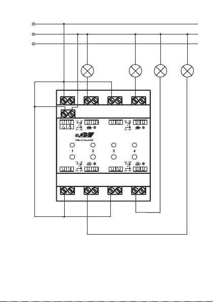
Verdrahten Sie den Netzanschluss und die
Lastanschlüsse mit der 230 V-Netzspannung gemäß
dem auf der folgenden Seite abgebildeten
Anschlussbild.
Vergewissern Sie sich, dass alle Anschlüsse
fest und sicher in den Installationsklemmen
fixiert sind.
11
L
N
PE
12
1 2 4 3

Klemme Funktion
1.2 Spannungsversorgung (Außenleiter)
1.6 Spannungsversorgung (Neutralleiter)
1.1, 1.5 Außenleiteranschluss Kanal 1
2.1, 2.5 Geschaltete Phase Kanal 1
3.1, 3.5 Außenleiteranschluss Kanal 2
4.1, 4.5 Geschaltete Phase Kanal 2
1.4, 1.8 Außenleiteranschluss Kanal 3
2.4, 2.8 Geschaltete Phase Kanal 3
3.4, 3.8 Außenleiteranschluss Kanal 4
4.4, 4.8 Geschaltete Phase Kanal 4
Die Schaltkanäle besitzen potentialfreie Relaiskontakte.
Die Gesamtanschlusslast darf 25 A nicht
überschreiten.
Zugelassene Leitungsquerschnitte zum Anschluss
an den Aktor:
starre Leitung
2
]
[mm
flexible Leitung mit Aderendhülse [mm2]
0,14 – 2,50 0,14 – 1,50
13

7 Inbetriebnahme
7.1 Einfache Bedienfunktionen mit
integrierten Tastern
Am Gerät ist pro Kanal ein Bedientaster vorhanden.
Sie können den Aktor über diese sofort bedienen
(Anlernen nicht erforderlich) und die korrekte
elektrische Installation überprüfen.
Zum Bedienen wird nur der kurze
Tastendruck verwendet. Der lange
Tastendruck (länger als 4 Sekunden) versetzt
den entsprechenden Kanal des Aktors in den
Anlernmodus.
Die jeweilige Kanal-LED signalisiert den Schaltzustand des Relais:
LED leuchtet - Relaiskontakt eingeschaltet
LED aus - Relaiskontakt abgeschaltet
14

7.2 Anlernen
Bitte lesen Sie diesen Abschnitt erst vollständig,
bevor sie mit dem Anlernen beginnen!
Zum Anlernen müssen beide zu verknüpfenden
Geräte in den Anlernmodus gebracht werden.
Zudem muss der gewünschte Kanal des Schaltaktors ausgewählt werden.
Beim Anlernen an eine Zentrale kann ein beliebiger
Kanal ausgewählt werden.
Zum Anlernen gehen Sie wie folgt vor.
· Drücken Sie die gewünschte Kanaltaste für etwa 4
Sekunden.
Dauerhaftes Blinken der jeweiligen Kanal-LED
signalisiert den aktivierten Anlernmodus.
· Bringen Sie nun das zweite Gerät in den Anlern-
modus, lesen Sie dazu die Bedienungsanleitung
des entsprechenden Gerätes.
· Wenn sich ein anderes HomeMatic-Gerät jetzt
auch im Anlernmodus befindet, wird dieses an den
ausgewählten Kanal des Schaltaktors angelernt.
Wenn kein Anlernen erfolgt, wird der Anlernmodus
automatisch nach 20 Sekunden beendet.
15

8 Bedienung
Nach dem Anlernen stehen einfache Bedienfunktionen
über die angelernten Bedienelemente zur Verfügung.
Je nach angelerntem Bedienelement lässt sich der
Schaltaktor im Zweitasten-AN/AUS Betrieb oder
im Toggle-Betrieb, z. B. durch nur eine Taste einer
entsprechend programmierten Fernbedienung
ansteuern.
9 Zurücksetzen in den
Auslieferungszustand
Um den Aktor in den Auslieferungszustand
zurückzusetzen, versetzen Sie das Gerät über die
erste Kanaltaste in den Anlernmodus (mindestens 4
Sekunden Taste gedrückt halten). Befindet sich das
Gerät im Anlernmodus, halten Sie erneut die erste
Kanaltaste für mindestens 4 Sekunden gedrückt.
Schnelles Blinken der Geräte-LED zeigt das
Rücksetzen des Aktors an.
16

10 Rückmeldungen der Geräte-LED
10.1 Blinkcodes
Verschiedene Zustände des Aktors werden durch
Blinken der Kanal-LEDs angezeigt:
Langsames Blinken Anlernmodus
Schnelles Blinken Reset
Einmal lang, n-mal kurz
(je nach Fehlerart)
10.2 Anzeige des Betriebszustandes
Sobald das Relais eines Kanals angezogen (bzw.
eingeschaltet) ist, leuchtet die entsprechende KanalLED dauerhaft.
Nach Konfiguration des Aktors über die Zentrale
oder über ein Programmiertool zeigt die GeräteLED neben den beschriebenen noch zusätzliche
Zustände des Geräts an.
Fehler
17

11 Verhalten nach
Spannungswiederkehr
Nach dem Einschalten der Betriebsspannung
(Wiederkehr der Netzspannung) überprüft der Aktor
seine Komponenten. Sollte dabei ein Fehler
festgestellt werden, so wird dieses durch
gemeinsames Blinken aller Kanal-LEDs dargestellt.
Dieses wiederholt sich kontinuierlich und das Gerät
nimmt seine eigentliche Funktion nicht auf.
Sollte der Test ohne Fehler durchlaufen, sendet der
Aktor ein Funktelegramm mit seiner Statusinformation aus. Damit bei Spannungswiederkehr (etwa
nach Netzspannungsausfall oder Abschaltung) nicht
alle Aktoren gleichzeitig senden, wartet der Aktor
eine zufällige Verzögerungszeit vor dem Senden.
In dieser Zeit blinken die Kanal-LEDs (wie im Anlernmodus). Ist die Verzögerungszeit sehr kurz, kann
es sein, dass das Blinken kaum wahrnehmbar ist.
12 Wartung und Reinigung
Das Produkt ist wartungsfrei. Überlassen Sie eine
Reparatur einer Fachkraft.
18

13 Technische Daten
Funkfrequenz: 868,3 MHz
Typ. Freifeldreichweite: 100 m
Spannungsversorgung: 230 V / 50 Hz
Standby-Verbrauch: 0,5 W
Schutzart: IP20
Schutzklasse: II
Ausgänge: 4 potentialfreie Relais-
Schaltvermögen: 230 V 50 Hz / 16 A (pro
Summe aller Kanäle max.
Abmessungen: Standard-Hutschienen(B x H x T) gehäuse, 4 TE
72 x 65 x 87 mm
Entsorgungshinweis
Gerät nicht im Hausmüll entsorgen!
Elektronische Geräte sind entsprechend
der Richtlinie über Elektro- und ElektronikAltgeräte über die örtlichen Sammelstellen
für Elektronik-Altgeräte zu entsorgen.
Schaltausgänge
Relais, ohmsche Last);
25 A
19

Das CE-Zeichen ist ein Freiverkehrszeichen,
das sich ausschließlich an die Behörden
wendet und keine Zusicherung von
Eigenschaften beinhaltet.
20

21

1. 1st English edition 08/2010
Documentation © 2010 eQ-3 Ltd., Hong Kong
All rights reserved. This manual may not be
reproduced in any format, either in whole or in part,
nor may it be duplicated or edited by electronic,
mechanical or chemical means, without the written
consent of the publisher.
Typographical and printing errors cannot be
excluded. However, the information contained in
this manual is reviewed on a regular basis and any
necessary corrections will be implemented in the
next edition. We accept no liability for technical or
typographical errors or the consequences thereof.
All trademarks and industrial property rights are
acknowledged.
Printed in Hong Kong.
Changes may be made without prior notice as a
result of technical advances.
91751 / V 1.1
22

Table of contents
1 Information about this manual ...........24
2 Hazard information ....................24
3 Function............................. 27
4 General system information
about HomeMatic .....................29
5 General information about radio operation . 29
6 Installation ...........................31
7 Start-up ............................. 34
7.1 Simple operator functions
using integrated buttons................ 34
7.2 Teaching-in ..........................35
8 Operation............................ 36
9 Resetting to the initial state ............. 36
10 Device LED feedback ..................37
10.1 Flashing codes .......................37
10.2 Operating status display................ 37
11 Response to power recovery ............38
12 Maintenance and cleaning ..............38
13 Technical data ........................39
23

1 Information about this manual
Read this manual carefully before starting to use
your device.
Keep the manual so you can refer to it at a later date
should you need to.
If you hand over the device to other persons for use,
please hand over the operating manual as well.
Attention!
This indicates a hazard.
Note. This section contains important
additional information!
2 Hazard information
The actuator that is described is part of
a building installation. When planning
and setting up electrical installations,
the standards and guidelines which are
applicable in the country in which the
equipment is installed must be complied
with.
24

The device has been designed solely for operation on
a 230 V/50 Hz AC supply. Only qualified electricians (to
VDE 0100) are permitted to carry out work on the 230
V mains. Applicable accident prevention regulations
must be complied with whilst such work is being
carried out.
To avoid electric shock, disconnect the mains voltage
prior to starting work on the device (trip the miniature
circuit-breaker). Noncompliance with the installation
instructions can cause fire or introduce other hazards.
The device may only be operated indoors and must
be protected from the effects of damp and dust,
as well as solar or other methods of heat radiation.
Using this device for any purpose other than that
described in this operating manual does not fall
within the scope of intended use and shall invalidate
any warranty or liability.
Do not exceed the capacity specified for the device.
If this capacity is exceed, this could lead to the
destruction of the device, to a fire or to an electrical
accident.
The device has not been designed to support
safety disconnection.
25

Do not open the device: it does not contain
any components that need to be serviced
by the user. There is a risk of electric shock
if the device is opened. In the event of an
error, please return the device to our service
department.
When connecting to the device terminals,
take the permissible cables and cable cross
sections into account.
It is absolutely essential to take the technical
data (in particular the maximum permissible
switching capacity of the relay and the type
of load to be connected) into account before
connecting a load. All load data relates to
resistive loads.
Refer to the relevant installation regulations
when performing installations in distribution
systems.
26

3 Function
The actuator switches up to 4 connected consumers
with total switching capacity of 5750 VA (230 V/25
A) or 3680 VA (230 V/16 A) per channel on the
basis of received radio commands. Commands are
transmitted by actuating buttons or remote controls,
or via a software interface. It is also possible to
control actuators via taught-in sensors. When an
event occurs, the sensors transmit a command (in
the same way as a button). Refer to the manual
for the corresponding sensor for more detailed
information.
Mounted on a standard DIN rail within distribution
boards.
27

(A) Channel button, channel 1 … 4
(B) Channel LED, channel 1 … 4
(C) Power supply, 230 V
(D) Switching channel 1
(E) Switching channel 2
(F) Switching channel 3
(G) Switching channel 4
28

4 General system information
about HomeMatic
This device is part of the HomeMatic home control
system and works with the bi-directional BidCoS
wireless protocol. All devices are delivered in a
standard configuration. The functionality of the
device can also be configured with a programming
device and software. The additional functions
that can be made available in this way and
the supplementary functions provided by the
HomeMatic system when it is combined with other
components are described in the HomeMatic
System Manual.
All current technical documents and updates are
provided at www.HomeMatic.com.
®
5 General information
about radio operation
Radio transmission is performed on a non-exclusive
transmission path, which means that there is a
possibility of interference occurring.
29

Interference can also be caused by switching
operations, electrical motors or defective electrical
devices.
The range of transmission within buildings
can differ greatly from that available in the
open air. Besides the transmitting power and
the reception characteristics of the receiver,
environmental factors such as humidity in the
vicinity have an important role to play, as do
on-site structural/screening conditions.
eQ-3 Entwicklung GmbH hereby declares that
this device conforms with the essential requirements
and other relevant regulations of Directive
1999/5/EC.
You can find the full declaration of conformity at
www.HomeMatic.com.
30

6 Installation
Refer to the relevant installation regulations
when performing installations in distribution
systems.
Place the switching module onto the DIN rail and
lock it in position.
Make sure that the locating springs engage
properly and that the device is securely
seated on the rail.
Strip 8 mm from the ends of the power supply cable
and the cables to the loads, without damaging the
exposed wires. Observe the permissible cable cross
sections.
Wire the power supply connection and the
load connections to the 230 V mains voltage in
accordance with the connection diagram on the
following page.
Make sure that all connections are tight and
secured in the installation terminals.
31

L
N
PE
32
1 2 4 3

Terminal Function
1.2 Power supply (phase conductor)
1.6 Power supply (neutral conductor)
1.1, 1.5
Phase conductor connection, channel 1
2.1, 2.5 Switched phase channel 1
3.1, 3.5
Phase conductor connection, channel 2
4.1, 4.5 Switched phase channel 2
1.4, 1.8
Phase conductor connection, channel 3
2.4, 2.8 Switched phase channel 3
3.4, 3.8
Phase conductor connection, channel 4
4.4, 4.8 Switched phase channel 4
The switching channels have potential-free relay
contacts.
The total connected load of all channels must
not exceed 25 A.
Permitted cable cross sections for connecting to the
actuator:
Rigid cable
2
]
[mm
Flexible cable with ferrule
[mm2]
0.14 – 2.50 0.14 – 1.50
33

7 Start-up
7.1 Simple operator functions using
integrated buttons
The device features one control button per channel.
You can operate the actuator by means of these
buttons immediately (no teaching-in required)
and check that the electrical installation has been
performed correctly.
Simply press and release the button to
operate the actuator. Pressing and holding
down the button (for more than 4 seconds)
will switch the relevant channel of the
actuator to teach-in mode.
The relevant channel LED signals the switching
status of the relay:
LED on - relay contact enabled
LED off - relay contact disabled
34

7.2 Teaching-in
Please read this entire section before starting the
teach-in procedure.
To execute the teach-in procedure, both of the
devices to be connected must be in teach-in mode.
The required switching actuator channel must also
be selected.
When teaching in at a central control unit, any
channel can be selected.
To teach in, proceed as follows.
· Press the required channel button for about 4
seconds.
If the respective channel LED flashes continuously,
this signals that teach-in mode is active.
· Now put the second device into teach-in mode, for
more information see the operating instructions of
the relevant device.
· If another HomeMatic device is also in teach-in
mode, this is taught in on the selected switching
actuator channel.
If no teach-in operations are carried out, teach-in
mode will be exited automatically after 20 seconds.
35

8 Operation
After teach-in has been performed, simple operator
functions are available via the taught-in control
elements. Depending on the taught-in control
element, the switch actuator can be controlled by
means of an ON/OFF pair of buttons or by toggling,
e.g. just a single button on an appropriately
programmed remote control.
9 Resetting to the initial state
To reset the actuator to the initial state, put the
device into teach-in mode using the first channel
button (hold it down for at least four seconds). If the
device is in teach-in mode, hold the first channel
button down for at least four seconds again. If the
device LED flashes quickly, this indicates that the
actuator is being reset.
36

10 Device LED feedback
10.1 Flashing codes
Various actuator states are indicated by the channel
LEDs flashing:
Slow flashing Teach-in mode
Fast flashing Reset
One long flash, n brief
flashes (depending on
the type of error)
10.2 Operating status display
As soon as a channel’s relay is picked up (i.e.
switched on), the corresponding channel LED lights
up continuously.
Once the actuator has been configured via the
central control unit or a programming tool, the
device LED will indicate other device states in
addition to those already described.
Error
37

11 Response to power recovery
When the operating voltage is switched on
(recovery of mains voltage), the actuator checks
its components. If an error is detected, all channel
LEDs will flash. This is repeated continuously and
the device does not perform its function. If the test
is completed without errors, the actuator transmits a
wireless telegram containing its status information.
To prevent all actuators from transmitting at the
same time when power is recovered (after a mains
power failure or a disconnection, for example), there
is a random delay before the actuator transmits.
During this time, the channel LEDs flash (as in
teach-in mode). If the delay is very short, this
flashing may be almost imperceptible.
12 Maintenance and cleaning
The product does not require any maintenance.
Enlist the help of an expert to carry out any repairs.
38

13 Technical data
Radio frequency: 868.3 MHz
Typ. open air range: 100 m
Power supply: 230 V/50 Hz
Standby consumption: 0.5 W
Degree of protection: IP20
Protection class: II
Outputs: 4 potential-free relay
switch outputs
Switching capacity: 230 V 50 Hz / 16 A (per
relay, resistive load);
Max. total for all
channels 25 A
Dimensions: Standard DIN
(W x H x D) rail housing, 4 WM
72 x 65 x 87 mm
Instructions for disposal
Do not dispose of the device with regular
domestic waste. Electronic equipment must
be disposed of at local collection points for
waste electronic equipment in compliance
with the Waste Electrical and Electronic
Equipment Directive.
39

The CE Marking is simply an official symbol
relating to the free movement of a product; it
does not warrant a product‘s characteristics.
eQ-3 AG
Maiburger Straße 29
D-26789 Leer
www.eQ-3.com
40
 Loading...