

Page 1
Installations- und
Bedienungsanleitung
Installation instruction and
operating manual
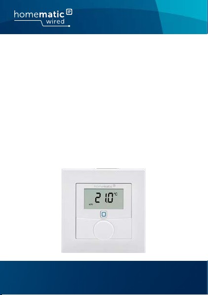
Wired Wandthermostat mit
Luftfeuchtigkeitssensor
Wired Wall Thermostat with
Humidity Sensor
HmIPW-WTH
S. 2
p. 44
Page 2

Lieferumfang
Anzahl Bezeichnung
1 Homematic IP Wired Wandthermostat
1 Wechselrahmen
1 Montageplatte
2 Schrauben 3,2 x 15 mm
2 Schrauben 3,2 x 25 mm
1 Bedienungsanleitung
Dokumentation © 2018 eQ-3 AG, Deutschland
Alle Rechte vorbehalten. Ohne schriftliche Zustimmung des
Herausgebers darf diese Anleitung auch nicht auszugsweise in
irgendeiner Form reproduziert werden oder unter Verwendung
elektronischer, mechanischer oder chemischer Verfahren vervielfältigt oder verarbeitet werden.
Es ist möglich, dass die vorliegende Anleitung noch drucktechnische Mängel oder Druckfehler aufweist. Die Angaben in dieser
Anleitung werden jedoch regelmäßig überprüft und Korrekturen
in der nächsten Ausgabe vorgenommen. Für Fehler technischer
oder drucktechnischer Art und ihre Folgen übernehmen wir keine
Haftung.
Alle Warenzeichen und Schutzrechte werden anerkannt.
Printed in Hong Kong
Änderungen im Sinne des technischen Fortschritts können ohne
Vorankündigung vorgenommen werden.
153480 (web)
Version 1.1 (07/2019)
mit Luftfeuchtigkeitssensor
Page 3
1
F
A
B
C
D
E
2
Page 4
3
G
4
Page 5
5
6
H
Page 6
7
8
Page 7

Inhaltsverzeichnis
1 Hinweise zur Anleitung ...................................................9
2 Gefahrenhinweise ............................................................9
3 Funktion und Geräteübersicht ....................................12
4 Allgemeine Systeminformationen ..............................14
5 Inbetriebnahme .............................................................. 14
5.1 Installationshinweise ...........................................................14
5.2 Installation .............................................................................17
5.3 Montage in Mehrfachkombinationen ..............................18
5.4 Anlernen ................................................................................19
5.4.1 Anlernen an den Homematic IP Wired
Fußbodenheizungsaktor ...................................... 20
5.4.2 Anlernen an die Zentrale CCU3 ...........................21
5.4.3 Anlernen an die Homematic IP Cloud per
Wired Access Point ................................................ 24
6 Betriebsmodi und Konfiguration .................................26
6.1 Automatikbetrieb .................................................................27
6.2 Manueller Betrieb.................................................................27
6.3 Urlaubsmodus ..................................................................... 28
6.4 Bediensperre ........................................................................29
6.5 Programmierung der Heizprofile .................................... 30
6.5.1 Heizen oder Kühlen ............................................... 30
6.5.2 Heizprofilnummer ..................................................31
6.5.3 Heizprofil ................................................................. 34
6.5.4 Optimum-Start-/Stop-Funktion ......................... 35
6.6 Datum und Uhrzeit ............................................................. 35
6.7 Oset-Temperatur .............................................................. 36
7
Page 8

6.8 Auswahl der gewünschten Temperaturanzeige ........... 36
6.9 Konfiguration des Fußbodenheizungsaktors ................. 37
6.10 Verbindungstest .................................................................. 38
7 Bedienung ........................................................................38
8 Fehlercodes und Blinkfolgen .......................................39
9 Wiederherstellung der Werkseinstellungen ..............41
10 Wartung und Reinigung ................................................ 41
11 Technische Daten ..........................................................42
8
Page 9
Hinweise zur Anleitung
1 Hinweise zur Anleitung
Lesen Sie diese Anleitung sorgfältig, bevor Sie Ihr Homematic IP Wired Gerät in Betrieb nehmen. Bewahren Sie
die Anleitung zum späteren Nachschlagen auf!
Wenn Sie das Gerät anderen Personen zur Nutzung überlassen, übergeben Sie auch diese Anleitung.
Benutzte Symbole:
Achtung!
Hier wird auf eine Gefahr hingewiesen.
Hinweis. Dieser Abschnitt enthält zusätzliche
wichtige Informationen.
2 Gefahrenhinweise
Önen Sie das Gerät nicht. Es enthält keine durch
den Anwender zu wartenden Teile. Lassen Sie das
Gerät im Fehlerfall von einer Fachkraft prüfen.
Aus Sicherheits- und Zulassungsgründen (CE) ist
das eigenmächtige Umbauen und/oder Verändern des Geräts nicht gestattet.
9
Page 10
Gefahrenhinweise
Verwenden Sie das Gerät nicht, wenn es von außen erkennbare Schäden, z. B. am Gehäuse, an
Bedienelementen oder an den Anschlussbuchsen
ausweist. Lassen Sie das Gerät im Zweifelsfall von
einer Fachkraft prüfen.
Betreiben Sie das Gerät nur in trockener sowie
staubfreier Umgebung, setzen Sie es keinem Einfluss von Feuchtigkeit, Vibrationen, ständiger
Sonnen- oder anderer Wärmeeinstrahlung, Kälte
und keinen mechanischen Belastungen aus.
Das Gerät ist kein Spielzeug! Erlauben Sie Kindern
nicht damit zu spielen. Lassen Sie das Verpackungsmaterial nicht achtlos liegen. Plastikfolien/
-tüten, Styroporteile etc. können für Kinder zu
einem gefährlichen Spielzeug werden.
Bei Sach- oder Personenschäden, die durch unsachgemäße Handhabung oder Nichtbeachten
der Gefahrenhinweise verursacht werden, übernehmen wir keine Haftung. In solchen Fällen erlischt jeder Gewährleistungsanspruch! Für Folgeschäden übernehmen wir keine Haftung!
Beachten Sie beim Anschluss an die Geräteklemmen die hierfür zulässigen Leitungen und Leitungsquerschnitte.
10
Page 11
Gefahrenhinweise
Das Gerät ist Teil der Gebäudeinstallation. Bei der
Planung und Errichtung sind die einschlägigen
Normen und Richtlinien des Landes zu beachten.
Das Gerät ist ausschließlich für den Betrieb am
Homematic IP Wired Bus vorgesehen. Der
Homematic IP Wired Bus ist ein SELV-Stromkreis.
Eine gemeinsame Führung der Netzspannung
und des Homematic IP Wired Bus in Installationsoder Verteilerdosen ist nicht zulässig. Die notwendige Isolation einer Netzspannung der Hausinstallation zum Homematic IP Wired Bus ist
immer einzuhalten. Bei Nichtbeachtung der Installationshinweise können Brand oder andere
Gefahren entstehen.
Das Gerät darf nur für ortsfeste Installationen verwendet werden. Das Gerät ist sicher innerhalb
einer festen Installation zu fixieren.
Beachten Sie die Installationsvorschriften für Installationen in Verteilersystemen (DIN VDE 0100-
410).
Das Gerät ist nur für den Einsatz in Wohnbereichen, Geschäfts- und Gewerbebereichen sowie
in Kleinbetrieben bestimmt.
11
Page 12

Funktion und Geräteübersicht
Jeder andere Einsatz, als der in dieser Bedienungsanleitung beschriebene, ist nicht bestimmungsgemäß und führt zu Gewährleistungs- und
Haftungsausschluss.
3 Funktion und Geräteübersicht
Mit dem Homematic IP Wired Wandthermostat können Sie
Ihre Fußbodenheizung in Verbindung mit HomematicIP
Fußbodenheizungsaktoren zeitgesteuert regulieren und
Heizphasen auf Ihre individuellen Bedürfnisse anpassen.
Der Wandthermostat misst die Temperatur und Luftfeuchtigkeit im Raum und gibt diese zyklisch an den Fußbodenheizungsaktor weiter, so dass die Raumtemperatur
exakt geregelt werden kann.
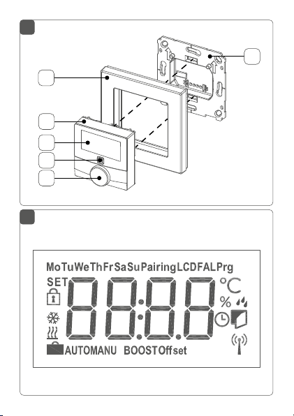
Geräteübersicht (s. Abbildung 1):
(A) Wechselrahmen
(B) Elektronikeinheit (Thermostat)
(C) Display
(D) Systemtaste (Anlerntaste und LED)
(E) Stellrad
(F) Montageplatte
12
Page 13
Funktion und Geräteübersicht
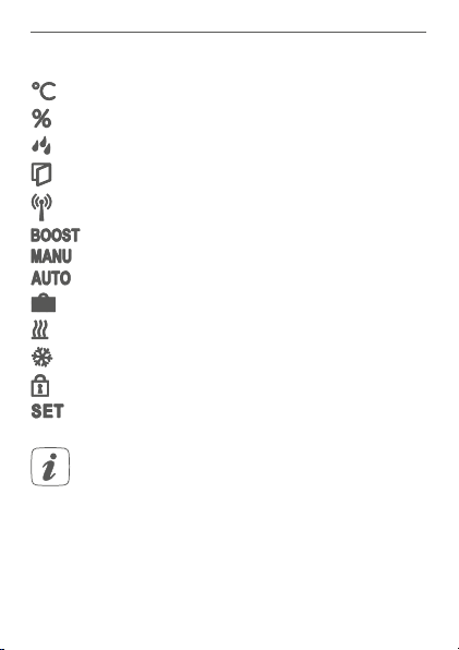
Displayübersicht (s. Abbildung 2):
Soll-/Ist-Temperatur
Luftfeuchtigkeit
Warnung für Betauung
Fenster-auf-Symbol
Funkübertragung
Boost-Funktion
Manueller Betrieb
Automatikbetrieb
Urlaubsmodus
Heizen
Kühlen
Bediensperre
Soll-Temperatur
Alle weiteren Symbole finden Sie im Kapitel „6
Betriebsmodi und Konfiguration“ auf Seite 26.
13
Page 14

Allgemeine Systeminformationen
4 Allgemeine Systeminformationen
Dieses Gerät ist Teil des Homematic IP Smart-Home-Systems und kommuniziert über das HomematicIP Protokoll.
Sie haben die Möglichkeit, alle Geräte des Systems komfortabel und individuell über die Bedienoberfläche der Zentrale CCU3 oder flexibel per Smartphone über die HomematicIP App in Verbindung mit der Homematic IP Cloud
zu konfigurieren. Welcher Funktionsumfang sich innerhalb
des Systems im Zusammenspiel mit weiteren Komponenten ergibt, entnehmen Sie bitte dem HomematicIP Wired
Systemhandbuch. Alle technischen Dokumente und Updates finden Sie stets aktuell unter www.eQ-3.de.
5 Inbetriebnahme
5.1 Installationshinweise
Da der Bus vom Homematic IP Wired Access
Point (HmIPW-DRAP) gespeist wird, müssen Sie
für die Spannungsversorgung des Geräts zunächst einen Homematic IP Wired Access Point
(HmIPW-DRAP) in Betrieb nehmen.
Bitte notieren Sie sich vor der Installation die auf
dem Gerät angebrachte Gerätenummer (SGTIN)
und den Verwendungszweck, damit Sie das Gerät
im Nachhinein leichter zuordnen können. Alternativ steht die Gerätenummer auch auf dem beiliegenden QR-Code-Aufkleber.
14
Page 15
Inbetriebnahme
Beachten Sie die auf dem Gerät angegebene Abisolierlänge der anzuschließenden Leiter.
Beachten Sie bei der Installation die Gefahrenhinweise gemäß „2 Gefahrenhinweise“ auf Seite 9.
Hinweis! Installation nur durch Personen mit
einschlägigen elektrotechnischen Kenntnissen
und Erfahrungen!*
Durch eine unsachgemäße Installation gefährden Sie
• Ihr eigenes Leben;
• das Leben der Nutzer der elektrischen Anlage.
Mit einer unsachgemäßen Installation riskieren Sie
schwere Sachschäden, z. B. durch Brand. Es droht für Sie
die persönliche Haftung bei Personen- und Sachschäden.
Wenden Sie sich an einen Elektroinstallateur!
Erforderliche Fachkenntnisse für die Installation:
*
Für die Installation sind insbesondere folgende Fachkenntnisse erforderlich:
• Die anzuwendenden „5 Sicherheitsregeln“:
Freischalten; gegen Wiedereinschalten sichern;
Spannungsfreiheit feststellen; Erden und Kurzschließen;
benachbarte, unter Spannung stehende Teile abdecken
oder abschranken;
• Auswahl des geeigneten Werkzeuges, der Messgeräte
und ggf. der persönlichen Schutzausrüstung;
• Auswertung der Messergebnisse;
• Auswahl des Elektroinstallationsmaterials zur Sicherstel-
15
Page 16
Inbetriebnahme
lung der Abschaltbedingungen;
• IP-Schutzarten;
• Einbau des Elektroinstallationsmaterials;
• Art des Versorgungsnetzes (TN-System, IT-System,
TT-System) und die daraus folgenden Anschlussbedingungen (klassische Nullung, Schutzerdung, erforderliche
Zusatzmaßnahmen etc.).
Zugelassene Leitungsquerschnitte zum Anschluss an den
Wandthermostat sind:
Starre Leitung: 0,12-0,50 mm
2
Aus Gründen der elektrischen Sicherheit dürfen
zum Anschluss des Homematic IP Wired Bus ausschließlich folgende Leitungen eingesetzt werden:
• Fernmeldeleitung J-Y(ST)Y mit 2 x 2 x 0,8
(= 0,5mm²) oder 4 x 2 x 0,8 (= 0,5 mm²),
geschirmt, TP
• Ethernet-Verlegekabel S/FUTP, Typ Cat5e oder
höher mit 2 x 2 x AWG22 (= 0,34 mm²) oder
4x2 x AWG22 (= 0,34 mm²), geschirmt, TP
Der Schirm (Begleitdraht) muss am Busanschluss
des Wired Access Points (HmIPW-DRAP) auf “–“
(= Masse) aufgelegt werden. Am Wandthermostat
darf der Schirm nicht aufgelegt werden.
16
Page 17

Inbetriebnahme
5.2 Installation
Der Bus wird vom Homematic IP Wired Access
Point (HmIPW-DRAP) gespeist. Weitere Informationen dazu können Sie der Bedienungsanleitung
des Wired Access Points entnehmen.
Für die Installation gehen Sie wie folgt vor:
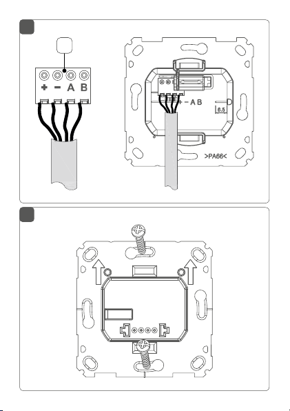
• Schließen Sie den Homematic IP Wired Bus an
die Busanschlussklemmen (G) an (s. Abbildung 3).
Zum Anschließen und Lösen der einzelnen Adern
betätigen sie den orangen Betätigungsdrücker
mit Hilfe eines kleinen Schraubendrehers.
• Setzen Sie die Montageplatte (F) in die Unterputzdose und befestigen Sie diese anschließend
mittels der mitgelieferten Schrauben an der Unterputzdose (s. Abbildung 4).
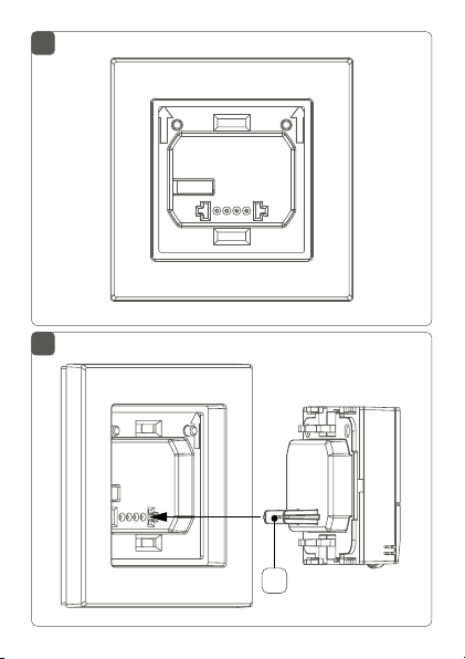
• Setzen Sie den Rahmen Ihrer vorhandenen Schalterserie oder den mitgelieferten Wechselrahmen
(A) auf die Montageplatte auf (s. Abbildung 5).
• Setzen Sie die Elektronikeinheit (B) des Wandthermostats in den Rahmen ein, indem Sie die
Verbindungsstifte (H) in die dafür vorgesehene
Halterung der Montageplatte vollständig einrasten (s. Abbildung 6+7).
17
Page 18

Inbetriebnahme
5.3 Montage in Mehrfachkombinationen
Sie können den Wandthermostat sowohl mit dem mitgelieferten Rahmen (A), als auch mit Rahmen anderer Hersteller verwenden oder die Elektronikeinheit (B) in einen
Mehrfachrahmen integrieren. Bei der Montage in Mehrfachkombinationen ist darauf zu achten, dass die Montageplatte des Wandthermostats bündig neben bereits
befestigte Montageplatten/Tragringen angebracht und
daran ausgerichtet wird. Die Rahmen folgender Hersteller
können verwendet werden:
Hersteller Rahmen
Berker S.1, B.1, B.3, B.7
Busch Jaeger
ELSO Joy
GIRA
merten
JUNG A 500, AS 500, A plus, A creation
Kopp Athenis
*mit 55er-Zwischenrahmen des Herstellers
18
carat*, future linear*, solo*, Buschaxcent*, Busch-dynasty*, balance SI
Standard 55, E2, E22, Event, Esprit,
ClassiX, E3
1-M, Atelier-M, M-Smart, M-Arc,
M-Star, M-Plan, M-Pure, System Antik*, System Fläche*, System Design*
Page 19

Inbetriebnahme
5.4 Anlernen
Bitte lesen Sie diesen Abschnitt erst vollständig,
bevor Sie mit dem Anlernen beginnen.
Detaillierte Informationen zu den Einrichtungsund Steuerungsmöglichkeiten entnehmen Sie
bitte dem Homematic IP Wired Systemhandbuch.
Damit der Wandthermostat in Ihr System integriert werden und mit anderen Geräten kommunizieren kann, muss
er zunächst angelernt werden. Sie haben folgende Einrichtungs- und Steuerungsmöglichkeiten für
thermostat:
den Wand-
Direktes Anlernen
direkt
Sie können den Wandthermostat
Fußbodenheizungsaktor
red
anlernen.
an den Wi-
Die Konfiguration erfolgt dann direkt über den Wandthermostat (s. „5.4.1 Anlernen an den Homematic IP Wired
Fußbodenheizungsaktor“ auf Seite 20).
Anlernen an die Zentrale CCU3
Für eine lokale, softwarebasierte Konfiguration und Steuerung per PC haben Sie die Möglichkeit, den Wandthermostat an die Zentrale CCU3 anzulernen und in umfangreichen Programmen zu nutzen (s. „5.4.2 Anlernen an die
Zentrale CCU3“ auf Seite 21).
19
Page 20

Inbetriebnahme
Anlernen an die Homematic IP Cloud
Für eine flexible Steuerung per kostenloser SmartphoneApp können Sie den Wandthermostat
an die Homematic IP Cloud anlernen (s. „5.4.3 Anlernen an die Homematic IP Cloud per Wired Access Point“ auf Seite 24).
Dabei ist es möglich, die Wired Geräte
• per Smartphone-App über den Homematic IP
Wired Access Point (HmIPW-DRAP) zu steuern
oder
• mit Homematic IP Funk-Komponenten über den
Homematic IP Access Point (HmIP-HAP) zu kombinieren.
5.4.1 Anlernen an den Homematic IP Wired
Fußbodenheizungsaktor
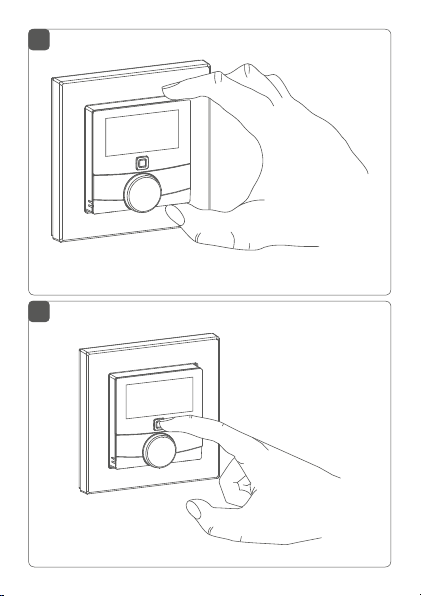
Sie können den Anlernvorgang durch erneute
kurze Betätigung der Systemtaste (D) abbrechen.
Dies wird durch ein rotes Aufleuchten der LED (D)
bestätigt.
Wenn kein Anlernen erfolgt, wird der Anlernmodus automatisch nach 30 Sekunden beendet.
Wenn Sie den Wandthermostat an einen HomematicIP
Wired
Fußbodenheizungsaktor anlernen möchten, müssen die beiden zu verknüpfenden Geräte in den Anlernmodus gebracht werden. Dafür gehen Sie wie folgt vor:
• Wählen Sie am Fußbodenheizungsaktor den
20
Page 21

Inbetriebnahme
gewünschten Kanal aus, an den Sie den Wandthermostat anlernen möchten. Weitere Informationen dazu können Sie der Bedienungsanleitung
des Fußbodenheizungsaktors entnehmen.
• Drücken Sie für 4 s auf die Systemtaste des Fußbodenheizungsaktors, bis die LED schnell orange zu blinken beginnt. Der Anlernmodus für den
ausgewählten Kanal ist für 3 Minuten aktiv.
• Drücken Sie die Systemtaste (D) des Wandthermostaten für mind. 4s, um den Anlernmodus zu
aktivieren (s. Abbildung 3). Die LED blinkt orange.
Erfolgreiches Anlernen wird durch grünes Blinken der
LED (D) signalisiert.
War der Anlernvorgang nicht erfolgreich, leuchtet die
LED (D) rot auf. Versuchen Sie es erneut.
5.4.2 Anlernen an die Zentrale CCU3
Um das HomematicIP Wired Gerät softwarebasiert und
komfortabel steuern und konfigurieren sowie in Zentralenprogrammen nutzen zu können, müssen Sie es an die
WebUI anlernen. Um den Wandthermostat an die Zentrale CCU3 anzulernen, gehen Sie wie folgt vor:
• Richten Sie zunächst Ihre Zentrale CCU3 gemäß
der zugehörigen Bedienungsanleitung ein und lernen Sie den Homematic IP Wired Access Point an.
• Starten Sie die Benutzeroberfläche „WebUI“ auf
Ihrem PC.
21
Page 22
Inbetriebnahme
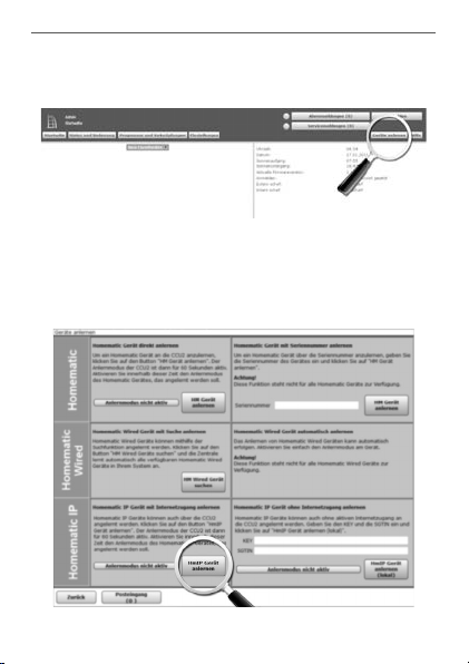
• Klicken Sie auf den Button „Geräte anlernen“ im
rechten oberen Bereich des Browserfensters.
• Um den Anlernmodus zu aktivieren, klicken Sie
im nächsten Fenster auf „HmIP Gerät anlernen“.
Die Zentrale wird für 60 Sekunden in den Anlernmodus versetzt. Ein Infofeld zeigt die aktuell noch
verbleibende Anlernzeit.
22
Page 23

Inbetriebnahme
• Nach dem Herstellen der Spannungsversorgung
ist der Anlernmodus des Wandthermostats für 3
Minuten aktiv.
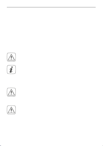
Sie können den Anlernmodus manuell für weitere
3 Minuten starten, indem Sie die Systemtaste (D)
kurz drücken (s. Abbildung 8).
• Warten Sie, bis der Anlernvorgang abgeschlossen
ist.
• Zur Bestätigung eines erfolgreichen Anlernvorgangs leuchtet die LED (D) grün. Das Gerät ist
nun einsatzbereit.
• Leuchtet die LED rot, versuchen Sie es erneut.
• Nach kurzer Zeit erscheint das neu angelernte
Gerät im Posteingang Ihrer Softwareoberfläche.
Neu angelernte Geräte und die zugehörigen Kanäle stehen erst dann für Bedien- und Konfigurationsaufgaben
zur Verfügung, nachdem sie im Posteingang konfiguriert
wurden. Weitere Informationen finden Sie im HomematicIP Wired Systemhandbuch unter www.eQ-3.de.
Im Betrieb ohne aktiven Internetzugang wählen
Sie die Option „Homematic IP Gerät ohne Inter-
netzugang anlernen“. Geben Sie zum Anlernen
die SGTIN und den Key des Geräts in die entsprechenden Felder ein. Die SGTIN und den Key
23
Page 24

Inbetriebnahme
finden Sie auf dem beiliegenden Sticker. Bitte bewahren Sie den Sticker sorgfältig auf.
5.4.3 Anlernen an die Homematic IP Cloud per Wired
Access Point
Wenn Sie Ihre Homematic IP Wired Geräte flexibel per
Smartphone-App steuern möchten, können Sie die
Homematic IP Wired Geräte einfach an die HomematicIP
Cloud anlernen. Gehen Sie dazu wie folgt vor:
• Önen Sie die Homematic IP App auf Ihrem
Smartphone.
• Lernen Sie den Homematic IP Wired Access Point
gemäß der zugehörigen Bedienungsanleitung
über die Smartphone-App an die Homematic IP
Cloud an.
• Wählen Sie den Menüpunkt „Gerät anlernen“ aus.
• Nach dem Herstellen der Spannungsversorgung
ist der Anlernmodus des Wandthermostats für 3
Minuten aktiv.
Sie können den Anlernmodus manuell für weitere
3 Minuten starten, indem Sie die Systemtaste (D)
kurz drücken (s. Abbildung 8).
• Das Gerät erscheint automatisch in der Homematic IP App.
• Zur Bestätigung geben Sie in der App die letzten
vier Ziern der Gerätenummer (SGTIN) ein oder
24
Page 25

Inbetriebnahme
scannen Sie den QR-Code. Die Gerätenummer
finden Sie auf dem Aufkleber im Lieferumfang
oder direkt am Gerät.
• Warten Sie, bis der Anlernvorgang abgeschlossen
ist.
• Zur Bestätigung eines erfolgreichen Anlernvorgangs leuchtet die LED (D) grün. Das Gerät ist
nun einsatzbereit.
• Leuchtet die LED rot, versuchen Sie es erneut.
• Wählen Sie die gewünschte Lösung für Ihr Gerät
aus.
• Vergeben Sie in der App einen Namen für das Gerät und ordnen Sie es einem Raum zu.
Wenn Sie bereits Homematic IP Geräte im SmartHome-System nutzen oder Ihre Wired Geräte mit
Funk-Komponenten von Homematic IP kombi
nieren möchten, können Sie die Homematic IP
Wir
ed Geräte auch einfach an einen (bestehenden) Homematic IP Access Point anlernen. Lernen
Sie dazu den Homema
tic IP Wired Access Point
gemäß der zugehörigen Bedienungsanleitung an
den (bestehenden) Homematic IP Access Point
an. Anschließend gehen Sie wie oben beschrieben
vor, um den Wandthermostat anzulernen.
25
-
Page 26

Betriebsmodi und Konfiguration
6 Betriebsmodi und Konfiguration
Nach dem Anlernen und der Montage können Sie über
das Konfigurationsmenü Einstellungen vornehmen, um
das Gerät an Ihre persönlichen Bedürfnissen anzupassen.
Gehen Sie dafür wie folgt vor:
• Drücken Sie lange auf das Stellrad (E), um das
Konfigurationsmenü zu önen.
• Wählen Sie das gewünschte Symbol durch Drehen und kurzes Drücken des Stellrads aus, um
Einstellungen für die folgenden Menüpunkt vorzunehmen.
Durch langes Drücken des Stellrads gelangen Sie
zur vorherigen Ebene zurück.
Wenn für mehr als 1 Minute keine Betätigung am
Gerät erfolgt, schließt sich das Menü automatisch,
ohne eingestellte Änderungen zu übernehmen.
6.1
6.2 Manueller Betrieb
6.3
6.4
6.5
6.6 Datum und Uhrzeit
6.7
6.8
26
Automatikbetrieb
Urlaubsmodus
Bediensperre
Programmierung der Heizprofile
Oset-Temperatur
Auswahl der gewünschten Temperaturanzeige
Page 27

Betriebsmodi und Konfiguration
6.9
6.10
Konfiguration des Fußbodenheizungsaktors
Verbindungstest
6.1 Automatikbetrieb
Im Automatikbetrieb erfolgt die Temperaturregelung gemäß des eingestellten Heizprofils (s. „6.5.3 Heizprofil“ auf
Seite 34). Manuelle Änderungen über das Stellrad (E)
bleiben bis zum nächsten Schaltzeitpunkt aktiv. Danach
wird das eingestellte Heizprofil wieder aktiviert. Um den
Automatikbetrieb zu aktivieren, gehen Sie wie folgt vor:
• Wählen Sie durch Drehen des Stellrads das Symbol „
durch kurzes Drücken des Stellrads.
“ aus und bestätigen Sie die Auswahl
6.2 Manueller Betrieb
Im manuellen Betrieb erfolgt die Temperaturregelung
gemäß der am Stellrad (E) eingestellten Temperatur. Die
Temperatur bleibt bis zur nächsten manuellen Änderung
erhalten. Um den manuellen Betrieb zu aktivieren, gehen
Sie wie folgt vor:
• Wählen Sie durch Drehen des Stellrads das Symbol „
durch kurzes Drücken des Stellrads.
• Drehen Sie das Stellrad, um die gewünschte Temperatur einzustellen.
“ aus und bestätigen Sie die Auswahl
27
Page 28

Betriebsmodi und Konfiguration
Sie können das Ventil des Fußbodenheizungsaktors vollständig schließen bzw. önen, indem Sie
das Stellrad (E) bis zum Anschlag gegen den Uhrzeigersinn bzw. mit dem Uhrzeigersinn drehen.
Im Display wird entsprechend „OFF“ bzw. „On“
angezeigt.
6.3 Urlaubsmodus
Der Urlaubsmodus kann genutzt werden, wenn für einen
bestimmten Zeitraum (z. B. während eines Urlaubs oder einer Party) eine feste Temperatur gehalten werden soll. Um
den Urlaubsmodus einzustellen, gehen Sie wie folgt vor:
• Wählen Sie durch Drehen des Stellrads das Sym-
• Stellen Sie durch Drehen des Stellrads Start-
• Stellen Sie durch Drehen des Stellrads End-Uhr-
• Stellen Sie durch Drehen des Stellrads die Tempe-
• Wählen Sie durch Drehen des Stellrads aus, für
28
“ aus und bestätigen Sie die Auswahl
bol „
durch kurzes Drücken des Stellrads.
Uhrzeit und -Datum ein und bestätigen Sie die
Auswahl durch kurzes Drücken des Stellrads. Das
„S“ zeigt an, dass es sich um die Startzeit handelt.
zeit und -Datum ein und bestätigen Sie die Auswahl durch kurzes Drücken des Stellrads. Das „E“
zeigt an, dass es sich um die Endzeit handelt.
ratur ein, die während der definierten Zeit gehalten werden soll und bestätigen Sie die Auswahl
durch kurzes Drücken des Stellrads.
Page 29

Betriebsmodi und Konfiguration
welche Räume der Urlaubsmodus aktiviert werden soll:
Auswahl „OnE“: Urlaubsmodus wird für den aktuellen Wandthermostat aktiviert.
Auswahl „ALL“: Urlaubsmodus wird für alle
Wandthermostate, die an den Fußbodenheizungsaktor angelernt sind, aktiviert.
6.4 Bediensperre
Die Bedienung am Gerät kann gesperrt werden, um das
ungewollte Verändern von Einstellungen, z. B. durch versehentliches Berühren, zu verhindern. Um die Bediensperre zu aktivieren bzw. deaktivieren, gehen Sie wie folgt vor:
• Wählen Sie durch Drehen des Stellrads das Sym-
• Wählen Sie durch Drehen des Stellrads „On“, um
“ aus und bestätigen Sie die Auswahl durch
bol „
kurzes Drücken des Stellrads.
die Bediensperre zu aktivieren oder „OFF“, um die
Bediensperre zu deaktivieren.
Ist die Bediensperre aktiviert, können Sie über das
Konfigurationsmenü nur den Menüpunkt für die
Bediensperre (
) aufrufen. Hierüber können Sie
die Bediensperre wieder deaktivieren.
29
Page 30

Betriebsmodi und Konfiguration
6.5 Programmierung der Heizprofile
Unter diesem Menüpunkt können Sie Einstellungen für
Ihre Heiz- bzw. Kühlprofile vornehmen und Heizprofile
nach Ihren eigenen Bedürfnissen erstellen.
• Wählen Sie durch Drehen des Stellrads das Sym-
• Wählen Sie durch Drehen des Stellrads
6.5.1 Heizen oder Kühlen
Sie können Ihre Fußbodenheizung im Winter zum Heizen
und im Sommer zum Kühlen verwenden.
• Wählen Sie im Menüpunkt „type“ durch Drehen
30
“ aus und bestätigen Sie die Auswahl
bol „
durch kurzes Drücken des Stellrads.
- „type“ für das Auswählen zwischen Heizen
(„HEAT“) oder Kühlen („COOL“),
- „Pr.nr“ für das Auswählen der Heizprofilnummer („nr. 1, nr. 2 ... nr. 6“),
- „Pr.Ad“ für das individuelle Einstellen des
Heizprofils und
- „OSSF“ zum Aktivieren („On“) bzw. Deaktivieren („OFF“) der Optimum-Start-/Stop-Funktion aus.
des Stellrads (E) „HEAT“ für Heizen oder „COOL“
für Kühlen aus und bestätigen Sie die Auswahl
durch kurzes Drücken des Stellrads.
Page 31

Betriebsmodi und Konfiguration
6.5.2 Heizprofilnummer
Sie können zwischen den 6 folgenden, bereits vorkonfigurierten Profilen wählen.
• Wählen Sie im Menüpunkt „Pr.nr.“ durch Drehen
des Stellrads (E) die Nummer des gewünschten
Profils aus und bestätigen Sie die Auswahl durch
kurzes Drücken des Stellrads.
Ist das gewählte Profil ein Heizprofil, wird geheizt,
sobald die Raumtemperatur unter den festgelegten Wert fällt. Ist das gewählte Profil ein Kühlprofil, wird gekühlt, sobald die Raumtemperatur über
den festgelegten Wert steigt.
Wird im Menü von „Heizen“ auf „Kühlen“ gewechselt, wird automatisch von Profil 1 auf 4, von Profil
2 auf 5 und von Profil 3 auf 6 gewechselt.
Profil 1
Vorkonfiguriert für Heizen per Heizkörperthermostat
Montag bis Freitag Temp.
00:00 bis 06:00 Uhr 17,0 °C
06:00 bis 09:00 Uhr 21,0 °C
09:00 bis 17:00 Uhr 17,0 °C
17:00 bis 22:00 Uhr 21,0 °C
22:00 bis 23:59 Uhr 17,0 °C
31
Page 32

Betriebsmodi und Konfiguration
Samstag bis Sonntag Temp.
00:00 bis 06:00 Uhr 17,0 °C
06:00 bis 22:00 Uhr 21,0 °C
22:00 bis 23:59 Uhr 17,0 °C
Profil 2
Vorkonfiguriert für Heizen per Fußbodenheizung
Montag bis Freitag Temp.
00:00 bis 05:00 Uhr 19,0 °C
05:00 bis 08:00 Uhr 21,0 °C
08:00 bis 15:00 Uhr 19,0 °C
15:00 bis 22:00 Uhr 21,0 °C
22:00 bis 23:59 Uhr 19,0 °C
Samstag bis Sonntag Temp.
00:00 bis 06:00 Uhr 19,0 °C
06:00 bis 23:00 Uhr 21,0 °C
23:00 bis 23:59 Uhr 19,0 °C
Profil 3
Alternatives Heizprofil
Montag bis Sonntag Temp.
00:00 bis 06:00 Uhr 17,0 °C
06:00 bis 22:00 Uhr 21,0 °C
22:00 bis 23:59 Uhr 17,0 °C
32
Page 33

Betriebsmodi und Konfiguration
Profil 4
Alternatives Kühlprofil 1
Montag bis Freitag Temp.
00:00 bis 06:00 Uhr 17,0 °C
06:00 bis 09:00 Uhr 21,0 °C
09:00 bis 17:00 Uhr 17,0 °C
17:00 bis 22:00 Uhr 21,0 °C
22:00 bis 23:59 Uhr 17,0 °C
Samstag bis Sonntag Temp.
00:00 bis 06:00 Uhr 17,0 °C
06:00 bis 22:00 Uhr 21,0 °C
22:00 bis 23:59 Uhr 17,0 °C
Profil 5
Vorkonfiguriert für Kühlen per Fußbodenheizung
Montag bis Freitag Temp.
00:00 bis 05:00 Uhr
23,0 °C
05:00 bis 08:00 Uhr 21,0 °C
08:00 bis 15:00 Uhr
23,0 °C
15:00 bis 22:00 Uhr 21,0 °C
22:00 bis 23:59 Uhr
23,0 °C
Samstag bis Sonntag Temp.
00:00 bis 06:00 Uhr
23,0 °C
06:00 bis 23:00 Uhr 21,0 °C
23:00 bis 23:59 Uhr
23,0 °C
33
Page 34

Betriebsmodi und Konfiguration
Profil 6
Alternatives Kühlprofil 1
Montag bis Sonntag Temp.
00:00 bis 06:00 Uhr 17,0 °C
06:00 bis 22:00 Uhr 21,0 °C
22:00 bis 23:59 Uhr 17,0 °C
6.5.3 Heizprofil
Im Heizprofil lassen sich für jeden Wochentag des gewählten Heizprofils separat bis zu 6 Heizphasen (13
Schaltzeitpunkte) individuell einstellen. Die Programmierung erfolgt für die ausgewählten Tage, wobei für einen
Zeitraum von 00:00 bis 23:59 Uhr Temperaturen hinterlegt werden können.
• Wählen Sie im Menüpunkt „Pr.Ad “ durch Drehen
des Stellrads (E) die Nummer des gewünschten
Profils aus und bestätigen Sie die Auswahl durch
kurzes Drücken des Stellrads.
• Wählen Sie unter „dAY“ durch Drehen des Stellrads bestimmte Wochentage, alle Werktage, das
Wochenende oder die gesamte Woche für Ihr
Heizprofil aus und bestätigen Sie die Auswahl
durch kurzes Drücken des Stellrads.
• Bestätigen Sie die Startzeit 00:00 Uhr durch kurzes Drücken des Stellrads.
• Wählen Sie durch Drehen des Stellrads die gewünschte Temperatur für die Startzeit aus und
34
Page 35

Betriebsmodi und Konfiguration
bestätigen Sie die Auswahl durch kurzes Drücken
des Stellrads.
• Im Display wird die nächste Uhrzeit angezeigt. Sie
können diese Zeit mit dem Stellrad verändern.
• Wählen Sie durch Drehen des Stellrads die gewünschte Temperatur für den nächsten Zeitabschnitt aus und bestätigen Sie die Auswahl durch
kurzes Drücken des Stellrads.
• Wiederholen Sie diesen Vorgang, bis für den gesamten Zeitraum von 0:00 bis 23:59 Uhr Temperaturen hinterlegt sind.
6.5.4 Optimum-Start-/Stop-Funktion
Damit zur festgelegten Zeit die gewünschte Temperatur
im Raum bereits erreicht wurde, können Sie die Optimum-Start-/Stop-Funktion aktivieren.
• Wählen Sie im Menüpunkt „OSSF“ durch Drehen
des Stellrads (E) „On“ für das Aktivieren oder „OFF“
für das Deaktivieren der Funktion aus und bestätigen Sie die Auswahl durch kurzes Drücken des
Stellrads.
6.6 Datum und Uhrzeit
Um Datum und Uhrzeit einzustellen, gehen Sie wie folgt
vor:
• Wählen Sie durch Drehen des Stellrads das Sym-
“ aus und bestätigen Sie die Auswahl durch
bol „
kurzes Drücken des Stellrads.
35
Page 36

Betriebsmodi und Konfiguration
• Stellen Sie durch Drehen des Stellrads Jahr, Monat, Tag und Uhrzeit ein und bestätigen Sie durch
kurzes Drücken des Stellrads.
6.7 Oset-Temperatur
Da die Temperatur am Wandthermostaten gemessen
wird, kann es an einer anderen Stelle im Raum kälter oder
wärmer sein. Um dies anzugleichen, kann eine OsetTemperatur von ±3.5 °C eingestellt werden. Werden z. B.
18 °C anstatt eingestellter 20 °C gemessen, ist ein Oset
von -2.0 °C einzustellen. Werksseitig ist eine Oset-Temperatur von 0.0 °C eingestellt. Um die Oset-Temperatur
individuell anzupassen, gehen Sie wie folgt vor:
• Wählen Sie durch Drehen des Stellrads das Symbol „
durch kurzes Drücken des Stellrads.
• Drehen Sie das Stellrad, bis die gewünschte Temperatur erscheint (max. ±3.5 °C).
• Bestätigen Sie durch kurzes Drücken des Stellrads.
“ aus und bestätigen Sie die Auswahl
6.8 Auswahl der gewünschten
Temperaturanzeige
Sie können festlegen, welche Temperatur und ob die
Luftfeuchtigkeit im Display angezeigt werden soll.
• Wählen Sie durch Drehen des Stellrads das Sym-
36
“ aus und bestätigen Sie die Auswahl
bol „
durch kurzes Drücken des Stellrads.
Page 37

Betriebsmodi und Konfiguration
• Wählen Sie durch Drehen des Stellrads
- „ACT“ für das Anzeigen der Ist-Temperatur,
- „SEt“ für das Anzeigen der Soll-Temperatur
oder
- „ACtH“ für das Anzeigen der Ist-Temperatur
und der aktuellen Luftfeuchtigkeit im Wechsel aus und bestätigen Sie Ihre Auswahl durch
kurzes Drücken des Stellrads.
6.9 Konfiguration des
Fußbodenheizungsaktors
Unter diesem Menüpunkt können Sie Einstellungen für
Ihren Homematic IP Wired Fußbodenheizungsaktor vornehmen.
• Wählen Sie durch Drehen des Stellrads das Sym-
• Ist der Wandthermostat an mehr als einen Fußbo-
• Wählen Sie aus, ob Sie Geräteparameter („UnP1/
• Stellen Sie Vor- sowie Nachlaufzeiten der Pumpe,
Weitere Informationen zu den Konfigurationsmöglich-
“ aus und bestätigen Sie die Auswahl
bol „
durch kurzes Drücken des Stellrads.
denheizungsaktor angelernt, wählen Sie mit dem
Stellrad die gewünschte Fußbodenheizung aus.
UnP2“) oder Kanalparameter („ChAn“) konfigurieren wollen.
Eco-Temperaturen, Zeitintervalle etc. ganz individuell ein.
37
Page 38

Bedienung
keiten entnehmen Sie bitte der Bedienungsanleitung des
Homematic IP Wired Fußbodenheizungsaktors.
6.10 Verbindungstest
Sie können die Verbindung zwischen Ihrem HomematicIP Wired Wandthermostat und dem Homematic IP Wired Fußbodenheizungsaktor überprüfen. Bei dieser Überprüfung sendet der Wandthermostat einen Schaltbefehl
an den Fußbodenheizungsaktor und je nachdem in welchem Schaltzustand sich der Aktor befindet, schaltet er
sich nach Erhalt des Befehls zur Bestätigung ein bzw. aus.
• Wählen Sie durch Drehen des Stellrads das Sym-
Der Verbindungstest wird durchgeführt.
“ aus und bestätigen Sie die Auswahl durch
bol „
kurzes Drücken des Stellrads.
7 Bedienung
Nach der Konfiguration stehen Ihnen einfache Bedienfunktionen direkt am Gerät zur Verfügung.
Befindet sich der Wandthermostat im Stand-byModus, müssen Sie vor der Bedienung einmal das
Stellrad (E) drücken, um ihn zu aktivieren.
• Temperatur: Drehen Sie das Stellrad (E) nach
rechts oder links, um die Temperatur manuell zu
38
Page 39

Fehlercodes und Blinkfolgen
verändern. Im Automatikbetrieb bleibt die manuell eingestellte Temperatur bis zum nächsten
Schaltzeitpunkt bestehen. Danach wird das eingestellte Heizprofil wieder aktiviert. Im manuellen
Betrieb bleibt die Temperatur bis zur nächsten
manuellen Änderung erhalten.
8 Fehlercodes und Blinkfolgen
Fehler- und
Blinkcode
Antennensymbol blinkt
)
(
Luftfeuchtesymbol blinkt
)
(
Betauungsund Kühlsymbol blinken
)
(
Schlosssymbol
)
(
Bedeutung Lösung
Kommunikationsstörung zur
Zentrale/zum
Fußbodenheizungsaktor
Feuchtegrenze
(60 %) im Raum
überschritten
Feuchteeingang bei Multi
IO Box wurde
aktiviert
Bediensperre
aktiv
Prüfen Sie die
Verbindung zur
Zentrale/Fußbodenheizungsaktor.
Lüften Sie und
stellen Sie ggf.
vom Kühl- auf
Heizbetrieb um.
Lüften Sie und
stellen Sie ggf. von
Kühl- auf Heizbetrieb um.
Deaktivieren Sie
die Bediensperre
in der App/im
Menü.
39
Page 40

Fehlercodes und Blinkfolgen
Kurzes
oranges
Blinken
1x langes
grünes
Leuchten
1x langes rotes
Leuchten
Kurzes
oranges
Blinken
(alle 10 s)
6x langes
rotes Blinken
1x oranges
und 1x grünes
Leuchten
(Spannungszufuhr)
40
Datenübertragung
Warten Sie, bis
die Übertragung
beendet ist.
Vorgang
bestätigt
Sie können mit
der Bedienung
fortfahren.
Vorgang
fehlgeschlagen
Anlernmodus
aktiv
Versuchen Sie es
erneut.
Geben Sie die
letzten vier Ziern
der Geräte-
Seriennummer zur
Bestätigung ein (s.
„5.4 Anlernen“ auf
Seite 19).
Gerät defekt Achten Sie auf die
Anzeige in Ihrer
App oder wenden
Sie sich an Ihren
Fachhändler.
Testanzeige Nachdem die
Testanzeige
erloschen ist,
können Sie fort-
fahren.
Page 41

Wiederherstellung der Werkseinstellungen
9 Wiederherstellung der
Werkseinstellungen
Die Werkseinstellungen des Geräts können wiederhergestellt werden. Dabei gehen alle Einstellungen verloren.
Um die Werkseinstellungen des Wandthermostats wiederherzustellen, gehen Sie wie folgt vor:
• Drücken Sie für 4 s auf die Systemtaste (D), bis
die LED schnell orange zu blinken beginnt (s. Ab-
bildung 8).
• Lassen Sie die Systemtaste wieder los.
• Drücken Sie die Systemtaste erneut für 4 s, bis die
LED grün aufleuchtet.
• Lassen Sie die Systemtaste wieder los, um das
Wiederherstellen der Werkseinstellungen abzuschließen.
Das Gerät führt einen Neustart durch. Nach dem Neustart
können Sie das Gerät wieder in Ihr Homematic IP System
integrieren.
10 Wartung und Reinigung
Das Gerät ist wartungsfrei. Überlassen Sie eine
Reparatur einer Fachkraft.
41
Page 42

Technische Daten
Reinigen Sie das Gerät mit einem weichen, sauberen,
trockenen und fusselfreien Tuch. Verwenden Sie keine
lösemittelhaltigen Reinigungsmittel, das Kunststogehäuse und die Beschriftung können dadurch angegrien
werden.
11 Technische Daten
Geräte-Kurzbezeichnung:
Versorgungsspannung: 24 VDC, +5 % -20 %, SELV
Stromaufnahme: 20 mA max.
Leitungsart u. -querschnitt: Starre Leitung
0,12-0,50 mm²
Installation: nur in Schalterdosen (Ge-
Schutzart: IP20
Schutzklasse: III
Umgebungstemperatur: 0 bis 50 °C
Abmessungen (B x H x T):
Ohne Rahmen: 55 x 55 x 42 mm
Mit Rahmen: 86 x 86 x 42 mm
Gewicht: 87 g
Wirkungsweise: Typ 1
Verschmutzungsgrad: 2
Software-Klasse: Klasse A
Stehstoßspannung: 330 V
Temperatur Glühdraht-
42
HmIPW-WTH
rätedosen) gemäß DIN
49073-1
Page 43

Technische Daten
prüfung: 850 °C
Temperatur Kugeldruckprüfung: 125 °C
PTI-Wert des Gehäusematerials: IIIb mit 100 < CTI < 175
Technische Änderungen vorbehalten.
Entsorgungshinweis
Gerät nicht im Hausmüll entsorgen! Elektronische Geräte sind entsprechend der Richtlinie
über Elektro- und Elektronik-Altgeräte über die
örtlichen Sammelstellen für Elektronik-Altgeräte
zu entsorgen.
Konformitätshinweis
Das CE-Zeichen ist ein Freiverkehrszeichen, das
sich ausschließlich an die Behörden wendet und
keine Zusicherung von Eigenschaften beinhaltet.
Bei technischen Fragen zum Gerät wenden Sie
sich bitte an Ihren Fachhändler.
43
Page 44

Package contents
Quantity Description
1 Homematic IP Wired Wall Thermostat with
Humidity Sensor
1 Clip-on frame
1 Mounting plate
2 Screws 3.2 x 15 mm
2 Screws 3.2 x 25 mm
1 User manual
Documentation © 2018 eQ-3 AG, Germany.
All rights reserved. Translation from the original version in German. This manual may not be reproduced in any format, either in
whole or in part, nor may it be duplicated or edited by electronic,
mechanical or chemical means, without the written consent of
the publisher.
Typographical and printing errors cannot be excluded. However,
the information contained in this manual is reviewed on a regular
basis and any necessary corrections will be implemented in the
next edition. We accept no liability for technical or typographical
errors or the consequences thereof.
All trademarks and industrial property rights are acknowledged.
Printed in Hong Kong
Changes may be made without prior notice as a result of technical advances.
153480 (web)
Version 1.1 (07/2019)
44
Page 45

Table of contents
1 Information about this manual....................................47
2 Hazard information ........................................................47
3 Function and device overview ................................... 50
4 General system information ........................................ 52
5 Start-up ............................................................................52
5.1 Installation instructions ..................................................... 52
5.2 Installation .............................................................................55
5.3 Installation in multiple combinations ..............................55
5.4 Teaching-in .......................................................................... 56
5.4.1 Pairing with a Homematic IP Floor Heating Actu-
ator ............................................................................ 58
5.4.2 Connecting to the CCU3 ..................................... 59
5.4.3 Connecting to the Homematic IP cloud via
Wired Access Point .................................................61
6 Operating modes and configuration .........................63
6.1 Automatic mode ................................................................. 64
6.2 Manual operation ................................................................ 64
6.3 Holiday mode ...................................................................... 65
6.4 Operating lock ..................................................................... 65
6.5 Programming of heating profiles ....................................66
6.5.1 Heating or cooling ..................................................67
6.5.2 Heating profile numbers .......................................67
6.5.3 Heating profile ........................................................ 70
6.5.4 Optimum start/stop function ...............................71
6.6 Date and time ....................................................................... 71
6.7 Oset temperature ..............................................................72
45
Page 46

6.8 Selecting the desired temperature display .....................72
6.9 Configuring the floor heating actuator ........................... 73
6.10 Communication test ...........................................................73
7 Operation .........................................................................74
8 Error codes and flashing sequences .......................... 75
9 Restore factory settings ................................................ 76
10 Maintenance and cleaning ........................................... 77
11 Technical specifications ................................................77
46
Page 47

Information about this manual
1 Information about this manual
Please read this manual carefully before beginning operation with your Homematic IP Wired component. Keep
the manual so you can refer to it at a later date if you
need to.
If you hand over the device to other persons for use,
please hand over this manual as well.
Symbols used:
Attention!
This indicates a hazard.
Please note: This section contains important additional information.
2 Hazard information
Do not open the device. It does not contain any
parts that can be maintained by the user. If you
have any doubts, have the device checked by an
expert.
For safety and licensing reasons (CE), unauthorized change and/or modification of the device is
not permitted.
47
Page 48

Hazard information
Do not use the device if there are signs of damage to the housing, control elements or connecting sockets, for example. If you have any doubts,
have the device checked by an expert.
The device may only be operated in dry and dustfree environment and must be protected from
the eects of moisture, vibrations, solar or other
methods of heat radiation, cold and mechanical
loads.
The device is not a toy; do not allow children to
play with it. Do not leave packaging material lying
around. Plastic films/bags, pieces of polystyrene,
etc. can be dangerous in the hands of a child.
We do not assume any liability for damage to
property or personal injury caused by improper
use or the failure to observe the hazard information. In such cases, any claim under warranty is
extinguished! For consequential damages, we assume no liability!
When connecting to the device terminals, take
the permissible cables and cable cross sections
into account.
48
Page 49

Hazard information
The device is part of the building installation. The
relevant national standards and directives must
be taken into consideration during planning and
set-up. The device is intended for operation
within the Homematic IP Wired bus only. The
Homematic IP Wired bus is a SELV power circuit.
Common cable routing for power supply and the
Homematic IP Wired bus in installation or
junction boxes is not permitted. The required
isolation for power supply of the building
installation to the Homematic IP Wired bus must
be observed at all times. Noncompliance with the
installation instructions can cause fire or
introduce other hazards.
The device may only be used for fixed installations. The device must be securely attached within a fixed installation.
Observe the installation instructions for installation in distribution systems (DINVDE0100-410).
The device may only be operated within domestic environment, in business and trade areas as
well as in small enterprises.
49
Page 50

Function and device overview
Using the device for any purpose other than that
described in this operating manual does not fall
within the scope of intended use and shall invalidate any warranty or liability.
3 Function and device overview
The Homematic IP Wired Wall Thermostat oers timecontrolled regulation of floor heating systems in connection with Homematic IP Floor Heating Actuators according to individually tailored heating phases.
The wall thermostat serves to measure the temperature
and humidity in a room. The data is cyclically transmitted
to floor heating actuators in order to regulate the room
temperature precisely.
Device overview (see figure 1):
(A) Clip-on frame
(B) Electronic unit (thermostat)
(C) Display
(D) System button (teach-in button and LED)
(E) Control wheel
(F) Mounting plate
50
Page 51

Function and device overview
Display overview (see figure 2):
Set/actual temperature
Humidity
Warning about condensation
Open window symbol
Radio transmission
Boost function
Manual operation
Automatic mode
Holiday mode
Heating
Cooling
Operating lock
Setpoint temperature
You will find a description of all symbols in section „6
Operating modes and configuration“ on page 63.
51
Page 52

General system information
4 General system information
This device is part of the Homematic IP smart home
system and works with the Homematic IP protocol. All
devices of the system can be configured comfortably
and individually with the user interface of the Central
Control Unit CCU3 or flexibly via the Homematic IP
smartphone app in connection with the Homematic IP
cloud. All available functions provided by the system
in combination with other components are described
in the Homematic IP Wired Installation Guide. All current technical documents and updates are provided at
www.eQ-3.com.
5 Start-up
5.1 Installation instructions
Since the power of the bus is supplied by the
Homematic IP Wired Access Point (HmIPWDRAP) you will need to set-up a Homematic IP
Wired Access Point for power supply first.
Before installation, please note the device number (SGTIN) labelled on the device as well as the
exact application purpose in order to make later
allocation easier. You can also find the device
number on the QR code sticker supplied.
52
Page 53

Start-up
Please note the insulation stripping length of the
conductor to be connected, indicated on the device.
Please observe the hazard information in section
„2 Hazard information“ on page 47 during installation.
Please note! Only to be installed by persons with
the relevant electro-technical knowledge and
experience!*
Incorrect installation can put
• your own life at risk;
• and the lives of other users of the electrical system.
Incorrect installation also means that you are running the
risk of serious damage to property, e.g. because of a fire.
You may be personally liable in the event of injuries or
damage to property.
Contact an electrical installer!
*Specialist knowledge required for installation:
The following specialist knowledge is particularly important during
installation:
• The “5 safety rules” to be used:
Disconnect from mains; Safeguard from switching on
again; Check that system is deenergised; Earth and short
circuit; Cover or cordon o neighbouring live parts;
• Select suitable tool, measuring equipment and, if neces-
53
Page 54

Start-up
sary, personal safety equipment;
• Evaluation of measuring results;
• Selection of electrical installation material for safeguarding shut-o conditions;
• IP protection types;
• Installation of electrical installation material;
• Type of supply network (TN system, IT system, TT system) and the resulting connecting conditions (classical
zero balancing, protective earthing, required additional
measures etc.).
Permitted cable cross sections for connecting to the wall
thermostat are:
Rigid cable: 0.12-0.50 mm
2
For reasons of electrical safety, only the following
cables must be used for connecting to the Homematic IP Wired bus:
• Telephone cable J-Y(ST)Y with 2 x 2 x 0.8
(= 0.5mm²) or 4 x 2 x 0.8 (= 0.5 mm²),
shielded, TP
• Ethernet installation cable S/FUTP, Type Cat5e or
higher with 2 x 2 x AWG22 (= 0.34 mm²) or
4 x 2 x AWG22 (= 0.34 mm²), shielded, TP
The shield (continuity wire) must be connected at
the bus connection of the Wired Access Point
(HmIPW-DRAP) to “–” (=GND). The shield may
not be connected to the wall thermostat.
54
Page 55

Start-up
5.2 Installation
The bus is supplied by the Homematic IP Wired
Access Point (HmIPW-DRAP). For further information, please refer to the operating manual of
the Wired Access Point.
For the installation, please proceed as follows:
• Connect the Homematic IP Wired bus to the bus
connecting terminals (G) (see fig. 3). For connection and removal of individual wires, use a small
screwdriver to press down the orange clamp.
• Place the mounting plate (F) into the flushmounted box and fix it to the flush-mounted box
using the supplied screws (see figure 4).
• Place the frame of your existing switch series or
the supplied clip-on frame (A) on the mounting
plate (A) (see figure 5).
• Place the electronic unit (B) of the wall thermostat into the frame, by properly engaging the
connection pins (H) into the appropriate bracket
of the mounting plate (see figure 6+7).
5.3 Installation in multiple combinations
You can mount the wall thermostat with the attachment
frame (A) provided or use it with frames of other
manufacturers as well as integrate the electronic unit
(B) into a multi-gang frame. For mounting with multiple
combinations, make sure that the mounting plate of the
55
Page 56

Start-up
wall thermostat is seamlessly aligned to the already fixed
mounting plate/retaining ring.
Frames of the following manufacturers can be used:
Manufacturer
Frame
Berker S.1, B.1, B.3, B.7
Busch Jaeger
carat*, future linear*, solo*, Busch-
axcent*, Busch-dynasty*, balance SI
ELSO Joy
GIRA Standard 55, E2, E22, Event, Esprit,
ClassiX, E3
merten 1-M, Atelier-M, M-Smart, M-Arc,
M-Star, M-Plan, M-Pure, System An-
tik*, System Fläche*, System Design*
JUNG A 500, AS 500, A plus, A creation
Kopp Athenis
*with 55 mm intermediate frames of the manufacturer
5.4 Teaching-in
Please read this entire section before starting
the teach-in procedure.
For detailed information about the setup and
control options, please refer to the HomematicIP Wired Installation Guide.
To integrate the wall thermostat into your system and
56
Page 57

Start-up
enable it to communicate with other devices, you must
teach it in first. The following set-up and control possibilities are available for
the wall thermostat:
Direct pairing
directly
You can
heating actuator
connect the wall thermostat to the
.
The configuration is then directly carried
floor
via the wall thermostat (see „5.4.1 Pairing with a Homematic IP Floor Heating Actuator“ on page 58).
Connecting to the Central Control Unit CCU3
For local, software-based configuration and control via
PC you have the possibility to connect the wall thermostat to the Central Control Unit CCU3 and use it in extensive programs (see „5.4.2 Connecting to the CCU3“ on
page 59).
Connecting to the Homematic IP cloud
For flexible control via the free smartphone app, you can
connect the wall thermostat to the Homematic IP cloud
(see „5.4.3 Connecting to the Homematic IP cloud via
Wired Access Point“ on page 61). You can
• control the wired system via smartphone app using the Homematic IP Wired Access Point (HmIPW-DRAP) or
• combine wired devices with wireless Homematic
IP devices via the Homematic IP Access Point
(HmIP-HAP).
57
Page 58

Start-up
5.4.1 Pairing with a Homematic IP Floor Heating
Actuator
You can cancel the pairing procedure by briefly
pressing the system button (D) again. This will be
indicated by the device LED (D) lighting red.
If no teach-in operations are carried out, teach-in
mode is exited automatically after 30 seconds.
If you want to pair the wall thermostat with a Homematic
Wired
Floor Heating Actuator, the pairing mode of both
IP
devices has to be activated first. To do this, proceed as
follows:
• Select the required channel on the floor heating
actuator that you want to connect to the wall
thermostat. For further information, please refer
to the operating manual of the floor heating actuator.
• Press and hold down the system button of the
floor heating actuator for 4 s until the LED quickly
starts flashing orange. The pairing mode of the
selected channel remains activated for 3 minutes.
• Press and hold down the system button (D) of
the wall thermostat for at least 4 seconds to activate the pairing mode (see fig. 3). The device LED
flashes orange.
58
Page 59

Start-up
The device LED (D) lights up green to indicate that pairing
has been successful. If pairing failed, the device LED (D)
lights up red. Please try again.
5.4.2 Connecting to the CCU3
To enable software-based and comfortable control and
configuration and for using the device in central control
unit program, it has to be connected to the WebUI. To
connect the wall thermostat to the Central Control Unit
CCU3, proceed as follows:
• Set up your Central Control Unit CCU3 as described in the operating manual and connect the
Homematic IP Wired Access Point.
• Start the user interface WebUI on your computer.
• Click the “Teach-in devices” button on the righthand side of the screen.
• To activate teach-in mode, click “Teach-in HmIP
device” in the next window. The teach-in mode
of the Central Control Unit will be activated for
60 seconds. An information box shows how
much teach-in time remains.
59
Page 60

Start-up
• After establishing the power supply, the teach-in
mode of the wall thermostat remains activated
for 3 minutes.
You can manually start the teach-in mode for another 3 minutes by pressing the system button
(D) briefly (see figure 8).
• Please wait until teach-in is completed.
• If teaching-in was successful, the LED (D) lights
up green. The device is now ready for use.
• If the LED lights up red, please try again.
• After a short time, the newly connected device
appears in the inbox of your software interface.
Newly connected devices and the corresponding channels are ready for operation and configuration only after
60
Page 61

Start-up
they have been configured in the inbox. You will find further information in the Homematic IP Wired Installation
Guide, available for download at www.eQ-3.com.
For operation without Internet connection,
please select the option “Teaching-in of Home-
matic IP device without Internet connection”.
Please enter the SGTIN and key of the device into
the corresponding fields. You will find the SGTIN
and the key on the supplied sticker. Please keep
the sticker in safe place.
5.4.3 Connecting to the Homematic IP cloud via
Wired Access Point
If you want to control your Homematic IP Wired devices
flexibly via smartphone app, they can be connected to
the Homematic IP cloud. To do this, please proceed as
follows:
• Open the Homematic IP app on your smartphone.
• Connect the Homematic IP Wired Access Point
via the smartphone app to the Homematic IP
cloud, as described in the corresponding user
manual
• Select the menu item “Teach-in device”.
• After establishing the power supply, the teach-in
mode of the wall thermostat remains activated
for 3 minutes.
61
Page 62

Start-up
You can manually start the teach-in mode for another 3 minutes by pressing the system button
(D) briefly (see figure 8).
• Your device will automatically appear in the
Homematic IP app.
• To confirm, please enter the last four digits of the
device number (SGTIN) in your app or scan the
QR code. Therefore, please see the sticker supplied or attached to the device.
• Please wait until teach-in is completed.
• If teaching-in was successful, the LED (D) lights
up green. The device is now ready for use.
• If the LED lights up red, please try again.
• Select the desired solution for your device.
• In the app, give the device a name and allocate
it to a room.
If you are already using Homematic IP devices in
your smart home system or if you want to combine your Homematic IP Wired devices with wireless Homematic IP components, you can also
connect the Homema
tic IP Wired devices to an
(installed) Access Point. Therefore, connect the
Homematic IP Wired Access Point to the (in
stalled) Homematic IP Access Point, as described
the user manual. Afterwards, please proceed as
in
described above to connect the wall thermostat.
62
-
Page 63

Operating modes and configuration
6 Operating modes and configuration
After teaching-in and mounting the device, you can individually adjust the settings to your personal needs via
the configuration menu. To do this, proceed as follows:
• Press and hold down the control wheel (E) to
open the configuration menu.
• Select the desired symbol by turning the control
wheel and pressing it briefly if you want to adjust
the settings of the following menu items.
Press and hold down the control wheel to get
back to the previous level. The menu automatically closes without applying changes if there is
no operation for more than 1 minute.
6.1 Automatic mode
6.2
6.3
6.4
6.5
6.6
6.7
6.8
6.9
6.10
Manual operation
Holiday mode
Operating lock
Programming of heating profiles
Date and time
Oset temperature
Selecting the desired temperature
display
Configuring the floor heating actuator
Communication test
63
Page 64

Operating modes and configuration
6.1 Automatic mode
In automatic mode, the temperature is controlled in accordance with the set heating profile (see „6.5.3 Heating
profile“ on page 70). Manual changes that are set via
the control wheel (E) are activated until the next point at
which the profile changes. Afterwards, the defined heating profile will be activated again. To activate the automatic mode, please proceed as follows:
• Select the
wheel and confirm by pressing the control wheel
briefly.
symbol by turning the control
6.2 Manual operation
In manual mode, the temperature is controlled in accordance with the current temperature set via the control wheel (E). The temperature remains activated until
the next manual change. To activate the manual mode,
please proceed as follows:
• Select the
wheel and confirm by pressing the control wheel
briefly.
• Turn the control wheel to set the desired temperature.
You can fully close or open the vale of the floor
heating actuator by turning the control wheel (E)
as far as it will go in an anti-clockwise or clockwise direction. “OFF” or “On” is displayed.
64
symbol by turning the control
Page 65

Operating modes and configuration
6.3 Holiday mode
The holiday mode can be used if you want to maintain a
fixed temperature for a certain period (e.g. during your
holidays or a party). To activate the holiday mode, please
proceed as follows:
• Select the
wheel and confirm by pressing the control wheel
briefly.
• Select the start time and date by turning the control wheel and confirm by pressing the control
wheel briefly. “S” indicates a start time.
• Select the end time and date by turning the control wheel and confirm by pressing the control
wheel briefly. “E” indicates an end time.
• Set the temperature that you want to maintain
during the defined time using the control wheel
and confirm by pressing the control wheel briefly.
• By turning the control wheel you can select the
rooms for activating the holiday mode.
Selecting “OnE”: Holiday mode is activated for
the current wall thermostat.
Selecting “ALL”: Holiday mode is activated for all
wall thermostats that are connected to the floor
heating actuator.
symbol by turning the control
6.4 Operating lock
Operation of the device can be locked to avoid settings
being changed unintended (e.g. through involuntary
65
Page 66

Operating modes and configuration
touch). To activate the operating lock, please proceed as
follows:
• Select the
symbol by turning the control wheel
and confirm by pressing the control wheel briefly.
• Turn the control wheel to select “On” in order to
activate the operating lock or “OFF” to deactivate
the operating lock.
If the operating lock is activated you can only enter the menu item “Operating lock” (
) via the
configuration menu. You can deactivate the operating lock here.
6.5 Programming of heating profiles
You can use this menu item for configuring heating and
cooling profiles and to adjust the heating profiles according to your personal needs.
• Select the
wheel and confirm by pressing the control wheel
briefly.
• Turn the control wheel and select
- “type” for switching between heating (”HEAT”)
or cooling (”COOL”),
- “Pr.nr” to set the heating profile number (”no.
1, no. 2 ... no. 6”),
- “Pr.Ad” for individual settings of the heating profile
and
- “OSSF” for activating (”On”) or deactivating
66
symbol by turning the control
Page 67

Operating modes and configuration
(”OFF”) the optimum start/stop function.
6.5.1 Heating or cooling
You can use your floor heating system to heat rooms during winter or to cool rooms during summer.
• Select “HEAT” for heating and “COOL” for cooling in the menu item “type” by turning the control
wheel (E) and confirm by pressing the control
wheel briefly.
6.5.2 Heating profile numbers
You can select between the following 6 pre-configured
profiles.
• Select the number of the required profile in the
menu item “Pr.nr.” by turning the control wheel
(E) and confirm by pressing the control wheel
briefly.
If the selected profile is a heating profile, the room
is heated as soon as the temperature falls below
the defined value. If the selected profile is a cooling profile, the room is cooled as soon as the temperature increases the defined value.
After switching from “heating” to “cooling” in the menu,
the profiles are changed from profile 1 to 4, profile 2 to 5
and from profile 3 to 6 automatically.
67
Page 68

Operating modes and configuration
Profile 1: Pre-configured heating via radiator thermostat
Monday to Friday Temp.
00:00 - 06:00 17.0 °C
06:00 - 09:00 21.0 °C
09:00 - 17:00 17.0 °C
17:00 - 22:00 21.0 °C
22:00 - 23:59 17.0 °C
Saturday to Sunday Temp.
00:00 - 06:00 17.0 °C
06:00 - 22:00 21.0 °C
22:00 - 23:59 17.0 °C
Profile 2: Pre-configured heating via floor heating
Monday to Friday Temp.
00:00 - 05:00 19.0 °C
05:00 - 08:00 21.0 °C
08:00 - 15:00 19.0 °C
15:00 - 22:00 21.0 °C
22:00 - 23:59 19.0 °C
Saturday to Sunday Temp.
00:00 - 06:00 19.0 °C
06:00 - 23:00 21.0 °C
23:00 - 23:59 19.0 °C
68
Page 69

Operating modes and configuration
Profile 3: Alternative profile
Monday to Sunday Temp.
00:00 - 06:00 17.0 °C
06:00 - 22:00 21.0 °C
22:00 - 23:59 17.0 °C
Profile 4: Alternative cooling profile 1
Monday to Friday Temp.
00:00 - 06:00 17.0 °C
06:00 - 09:00 21.0 °C
09:00 - 17:00 17.0 °C
17:00 - 22:00 21.0 °C
22:00 - 23:59 17.0 °C
Saturday to Sunday Temp.
00:00 - 06:00 17.0 °C
06:00 - 22:00 21.0 °C
22:00 - 23:59 17.0 °C
Profile 5: Pre-configured cooling via floor heating
Monday to Friday Temp.
00:00 - 05:00
23.0 °C
05:00 - 08:00 21.0 °C
08:00 - 15:00
23.0 °C
15:00 - 22:00 21.0 °C
22:00 - 23:59
23.0 °C
69
Page 70

Operating modes and configuration
Saturday to Sunday Temp.
00:00 - 06:00
23.0 °C
06:00 - 23:00 21.0 °C
23:00 - 23:59
23.0 °C
Profile 6: Alternative cooling profile 1
Monday to Sunday Temp.
00:00 - 06:00 17.0 °C
06:00 - 22:00 21.0 °C
22:00 - 23:59 17.0 °C
6.5.3 Heating profile
In the heating profile, for each weekday up to 6 heating phases (13 change settings) can be set separately. The
programming is carried out for the selected days, whereby temperature settings have to be set for the entire period between 00:00 and 23:59h.
• Select the number of the required profile in the
menu item “Pr.Ad” by turning the control wheel
(E) and confirm by pressing the control wheel
briefly.
• In the menu item “dAy” you can select single days
of the week, all weekdays, the weekend or the
entire week for your heating profile and confirm
by pressing the control wheel briefly.
• Confirm the start time 00:00 by pressing the
control wheel briefly.
70
Page 71

Operating modes and configuration
• Select the desired temperature for the start time
by turning the control wheel and confirm by
pressing the control wheel briefly.
• The next time is shown in the display. You can
change this time using the control wheel.
• Select the desired temperature for the next period by turning the control wheel and confirm by
pressing the control wheel briefly.
• Repeat this procedure until temperatures are
stored for the entire period between 0:00 and
23:59 h.
6.5.4 Optimum start/stop function
To reach the desired temperature in the room at the defined time you can activate the optimum start/stop function.
• Select “On” for activating or “OFF” for deactivating
the function in the menu item “OSSF” by turning
the control wheel (E) and confirm by pressing the
control wheel briefly.
6.6 Date and time
To set the date and time, please proceed as follows:
• Select the
and confirm by pressing the control wheel briefly.
• Set the year, month, day and hour by turning the
control wheel and confirm by pressing the control wheel briefly.
symbol by turning the control wheel
71
Page 72

Operating modes and configuration
6.7 Oset temperature
As the temperature is measured on the wall thermostat,
the temperature distribution can vary throughout a room.
To adjust this, a temperature oset of ±3.5 °C can be set.
If a nominal temperature of e.g. 20 °C is set but the room
presents with only 18 °C, an oset of -2.0 °C needs to
be set. An oset temperature of 0.0° is set in the factory
settings. To adjust the oset temperature, please proceed
as follows:
• Select the
wheel and confirm by pressing the control wheel
briefly.
• Turn the control wheel until the desired temperature appears (±3.5 °C maximum).
• Confirm by pressing the control wheel briefly.
symbol by turning the control
6.8 Selecting the desired temperature display
You can adjust the temperature to be displayed. You can
also define whether the humidity value shall be displayed
or not.
• Select the
wheel and confirm by pressing the control wheel
briefly.
• Turn the control wheel and select
- “ACT” to display the actual temperature,
- “SEt” to display the setpoint temperature,
- “ACtH” for alternating between the actual
temperature and humidity display and con-
72
symbol by turning the control
Page 73

Operating modes and configuration
firm by pressing the control wheel briefly.
6.9 Configuring the floor heating actuator
You can use this menu item for configuring your Homematic IP Wired Floor Heating Actuator.
• Select the
wheel and confirm by pressing the control wheel
briefly.
• If the wall thermostat is connected to more than
one floor heating actuator, please select the required floor heating using the control wheel.
• Please define if you want to configure the device
parameters (”UnP1/UnP2”) or the channel parameters (”ChAn”).
• You can individually adjust the line-up time/follow-up time, eco temperatures, intervals etc.
For further information regarding the configuration options, please refer to the user manual of the Homematic IP Floor Heating Actuator.
symbol by turning the control
6.10 Communication test
You can check the connection between your Homematic
IP Wired Wall Thermostat and the Homematic IP Wired
Floor Heating Actuator. During this test, the wall thermostat transmits a switching command to the floor heating
actuator. Depending on the current status of the actuator, the device is switched on or o for confirmation after
73
Page 74

Operation
receiving the command.
• Select the
and confirm by pressing the control wheel briefly.
The connection test is carried out.
symbol by turning the control wheel
7 Operation
After configuration, simple operations are available directly on the device.
If the wall thermostat is in standby mode, please
press the control wheel (E) once before operation
to activate the device.
• Temperature: Turn the control wheel (E) to the
right or to the left to manually change the temperature. In automatic mode, the manually set
temperature will remain the same until the next
point at which the profile changes. Afterwards,
the defined heating profile will be activated again.
During manual operation, the temperature remains activated until the next manual change.
74
Page 75

Error codes and flashing sequences
8 Error codes and flashing
sequences
Error and
flashing codes
Antenna
symbol flash-
)
ing (
Humidity
symbol flash-
)
ing (
Flashing
condensation
and cooling
symbol (
Lock symbol
)
(
Short orange
flashing
1x long green
lighting
1x long red
lighting
Meaning Solution
Communication error to
CCU/
to floor heating
actuator
Humidity
limit (60 %) in
the room is
exceeded
Humidity input
of Multi IO
Box has been
)
activated
Operating lock
activated
Data transfer Wait until the
Operation
confirmed
Operation
failed
Check the connection to the
CCU/
floor heating
actuator.
Ventilate the room
and switch from
cooling to heating
mode, if required.
Ventilate the room
and switch from
cooling to heating
mode, if required.
Deactivate the
operating lock
via the app or the
menu.
transmission is
completed.
You can continue
operation.
Please try again.
75
Page 76

Restore factory settings
Short orange
flashing
(every 10
seconds)
6x long red
flashing
1x orange and
1x green lighting (voltage
supply)
Teach-in mode
active
Device defective
Test display After the test dis-
Please enter the
last four numbers
of the device
serial number for
confirmation (see
„5.4 Teaching-in“
on page 56).
Please see your
app for error message or contact
your retailer.
play has stopped,
you can continue.
9 Restore factory settings
The factory settings of the device can be restored.
If you do this, you will lose all your settings.
To restore the factory settings of the wall thermostat,
please proceed as follows:
• Press and hold down the system button (D) for 4
seconds until the LED quickly starts flashing orange (see figure 8).
• Release the system button again.
• Press and hold down the system button again for
4 seconds, until the LED lights up green.
76
Page 77

Maintenance and cleaning
• Release the system button to finish the procedure.
The device will perform a restart. After the restart, you
can again integrate your device into your Homematic IP
system.
10 Maintenance and cleaning
The product does not require any maintenance.
Enlist the help of an expert to carry out any repairs.
Clean the device using a soft, lint-free cloth that is clean
and dry. Do not use any detergents containing solvents,
as they could corrode the plastic housing and label.
11 Technical specifications
Device short name:
Supply voltage: 24 VDC, +5 % -20 %, SELV
Current consumption: 20 mA max.
Cable type and cross section: Rigid cable
0.12-0.50 mm²
Installation: only in normal commer-
HmIPW-WTH
cial switch boxes (device
boxes) in accordance with
DIN 49073-1.
77
Page 78

Technical specifications
Degree of protection: IP20
Protection class: III
Ambient temperature: 0 to 50 °C
Dimensions (W x H x D):
Without frame: 55 x 55 x 42 mm
Including frame: 86 x 86 x 42 mm
Weight: 87 g
Method of operation: Type 1
Degree of pollution: 2
Software class: Class A
Withstand voltage: 330 V
Temperature of glow wire
test: 850 °C
Temperature of ball pressure
test: 125 °C
PTI value of housing
material: IIIb with 100 < CTI < 175
Subject to technical changes.
78
Page 79

Technical specifications
Instructions for disposal
Do not dispose of the device with regular domestic waste! Electronic equipment must be disposed of at local collection points for waste electronic equipment in compliance with the Waste
Electrical and Electronic Equipment Directive.
Information about conformity
The CE sign is a free trading sign addressed exclusively to the authorities and does not include
any warranty of any properties.
For technical support, please contact your retailer.
79
Page 80

Kostenloser Download der Homematic IP App!
Free download of the Homematic IP app!
Bevollmächtigter des Herstellers:
Manufacturer’s authorised representative:
eQ-3 AG
Maiburger Straße 29
26789 Leer / GERMANY
www.eQ-3.de
 Loading...