

Page 1
Installations- und
Bedienungsanleitung
Installating instruction and
operating manual
Wired Präsenzmelder – innen S. 2
Wired Precense Sensor – indoor p. 36
HmIPW-SPI
Page 2

Lieferumfang
Anzahl Bezeichnung
1 Homematic IP Wired Präsenzmelder – innen
1 Montageplatte
1 Installationsadapter für Deckenmontage
2 Dübel 5 mm
2 Schrauben 3,0 x 30 mm
4 Schrauben 3,2 x 15 mm
2 Schrauben 3,2 x 25 mm
2 Bedienungsanleitungen
1 Beiblatt mit Sicherheitshinweisen
Dokumentation © 2019 eQ-3 AG, Deutschland
Alle Rechte vorbehalten. Ohne schriftliche Zustimmung des
Herausgebers darf diese Anleitung auch nicht auszugsweise in
irgendeiner Form reproduziert werden oder unter Verwendung
elektronischer, mechanischer oder chemischer Verfahren vervielfältigt oder verarbeitet werden.
Es ist möglich, dass die vorliegende Anleitung noch drucktechnische Mängel oder Druckfehler aufweist. Die Angaben in dieser
Anleitung werden jedoch regelmäßig überprüft und Korrekturen
in der nächsten Ausgabe vorgenommen. Für Fehler technischer
oder drucktechnischer Art und ihre Folgen übernehmen wir keine
Haftung.
Alle Warenzeichen und Schutzrechte werden anerkannt.
Printed in Hong Kong
Änderungen im Sinne des technischen Fortschritts können ohne
Vorankündigung vorgenommen werden.
154135 (web)
Version 1.0 (08/2019)
Page 3

1
A
B
C
D
E
Page 4
2
H
I
F
G
3
1
40 mm
2 3
40
H
I
2x
Page 5
4
5
Page 6
6
2
1
7
Page 7
8
2
1
9
Page 8
10
11
Page 9
12
click
13
CCU
HomematicHomematic IP
*
Page 10
13
HAP
Homematic IP
14
4 s
4 s
Page 11

Inhaltsverzeichnis
1 Hinweise zur Anleitung ................................................. 12
2 Gefahrenhinweise .......................................................... 12
3 Funktion und Geräteübersicht .................................... 15
4 Allgemeine Systeminformationen .............................. 17
5 Erfassungsbereich ..........................................................18
6 Inbetriebnahme ............................................................. 20
6.1 Installationshinweise .......................................................... 20
6.2 Installation an der Decke .................................................. 23
6.3 Installation auf einer Unterputzdose .............................. 24
6.4 Anlernen ............................................................................... 26
6.4.1 Anlernen an die Zentrale CCU3 ...........................27
6.4.2 Anlernen an die Homematic IP Cloud per
Wired Access Point (zukünftig geplant) ............ 29
7 Funktionstest ................................................................... 31
8 Fehlercodes und Blinkfolgen .......................................32
9 Wiederherstellung der Werkseinstellungen ..............33
10 Wartung und Reinigung ................................................34
11 Technische Daten ..........................................................34
11
Page 12
Hinweise zur Anleitung
1 Hinweise zur Anleitung
Lesen Sie diese Anleitung sorgfältig, bevor Sie Ihre
Homematic IP Geräte in Betrieb nehmen. Bewahren Sie
die Anleitung zum späteren Nachschlagen auf!
Wenn Sie das Gerät anderen Personen zur Nutzung überlassen, übergeben Sie auch diese Anleitung.
Benutzte Symbole:
Achtung!
Hier wird auf eine Gefahr hingewiesen.
Hinweis.
Dieser Abschnitt enthält zusätzliche wichtige
Informationen!
2 Gefahrenhinweise
Önen Sie das Gerät nicht. Es enthält keine durch
den Anwender zu wartenden Teile. Lassen Sie das
Gerät im Fehlerfall von einer Fachkraft prüfen.
Aus Sicherheits- und Zulassungsgründen (CE) ist
das eigenmächtige Umbauen und/oder Verändern des Geräts nicht gestattet.
12
Page 13
Gefahrenhinweise
Verwenden Sie das Gerät nicht, wenn es von außen erkennbare Schäden, z. B. am Gehäuse, an
Bedienelementen oder an den Anschlussbuchsen
ausweist. Lassen Sie das Gerät im Zweifelsfall von
einer Fachkraft prüfen.
Betreiben Sie das Gerät nur in Innenräumen und
setzen Sie es keinem Einfluss von Feuchtigkeit,
Vibrationen, ständiger Sonnen- oder anderer
Wärmeeinstrahlung, übermäßiger Kälte und keinen mechanischen Belastungen aus.
Das Gerät ist kein Spielzeug! Erlauben Sie Kindern
nicht damit zu spielen. Lassen Sie das Verpackungsmaterial nicht achtlos liegen. Plastikfolien/
-tüten, Styroporteile etc. können für Kinder zu
einem gefährlichen Spielzeug werden.
Bei Sach- oder Personenschäden, die durch unsachgemäße Handhabung oder Nichtbeachten
der Gefahrenhinweise verursacht werden, übernehmen wir keine Haftung. In solchen Fällen erlischt jeder Gewährleistungsanspruch! Für Folgeschäden übernehmen wir keine Haftung!
Beachten Sie beim Anschluss an die Geräteklemmen die hierfür zulässigen Leitungen und Leitungsquerschnitte.
13
Page 14
Gefahrenhinweise
Das Gerät ist Teil der Gebäudeinstallation. Bei der
Planung und Errichtung sind die einschlägigen
Normen und Richtlinien des Landes zu beachten.
Das Gerät ist ausschließlich für den Betrieb am
Homematic IP Wired Bus vorgesehen. Der
Homematic IP Wired Bus ist ein SELV-Stromkreis.
Eine gemeinsame Führung der Netzspannung
und des Homematic IP Wired Bus in Installationsoder Verteilerdosen ist nicht zulässig. Die notwendige Isolation einer Netzspannung der Hausinstallation zum Homematic IP Wired Bus ist
immer einzuhalten. Bei Nichtbeachtung der Installationshinweise können Brand oder andere
Gefahren entstehen.
Das Gerät darf nur für ortsfeste Installationen verwendet werden. Das Gerät ist sicher innerhalb
einer festen Installation zu fixieren.
Beachten Sie die Installationsvorschriften für Installationen in Verteilersystemen (DIN VDE 0100-
410).
Jeder andere Einsatz, als der in dieser Bedienungsanleitung beschriebene, ist nicht bestimmungsgemäß und führt zu Gewährleistungs- und
Haftungsausschluss.
14
Page 15

Funktion und Geräteübersicht
Das Gerät ist nur für den Einsatz in Wohnbereichen, Geschäfts- und Gewerbebereichen sowie
in Kleinbetrieben bestimmt.
3 Funktion und Geräteübersicht
Der Homematic IP Wired Präsenzmelder erkennt zuverlässig die Anwesenheit von Personen durch Erfassung
feinster Bewegungen sowie die Umgebungshelligkeit. Der
Sensor kann sowohl grobe Bewegungen (wie bspw. das
Gehen von Personen) in einem weiten Bereich, als auch
feinste Bewegungen (z. B. Handbewegung auf einer Tastatur) in naher Umgebung wahrnehmen.
Sie können den leistungsfähigen Präsenzmelder z. B. für
Licht- oder Sicherheitsanwendungen einsetzen. Über die
Bewegungserkennung kann in Verbindung mit anderen
Homematic IP Wired Geräten Licht eingeschaltet oder
Alarm ausgelöst werden, wenn sich eine Person im Raum
aufhält.
Mit einem Erfassungsbereich von bis zu 7 m (bei einer
Montagehöhe von 2,7 m) sowie einem Erfassungswinkel
von 105° lässt sich der Präsenzmelder optimal den örtlichen Gegebenheiten anpassen. Das Gerät lässt sich einfach in eine Unterputzdose integrieren oder frei an der
Decke montieren.
15
Page 16

Funktion und Geräteübersicht
Eine hohe Raumtemperatur (z. B. bei Verwendung einer
Fußbodenheizung) kann die Empfindlichkeit von Präsenzmeldern beeinflussen. Der Präsenzmelder gleicht Temperatureinflüsse automatisch aus, um jederzeit eine präzise
Bewegungserkennung zu gewährleisten.
Geräteübersicht (s. Abbildung 1):
(A) Linse
(B) Systemtaste (Anlerntaste und LED)
(C) Elektronikeinheit (Präsenzmelder)
(D) Montageplatte
(E) Anschlussklemmen (Push-in-Klemme)
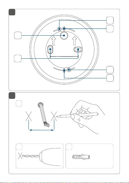
Übersicht Installationsadapter (s. Abbildung 2):
(F) Kabeldurchführung
(G) Schraublöcher
(H) Halterungen
Montagelöcher für Wired Installationsadapter
(I)
16
Page 17

Allgemeine Systeminformationen
4 Allgemeine Systeminformationen
Dieses Gerät ist Teil des Homematic IP Smart-Home-Systems und kommuniziert über das HomematicIP Protokoll.
Sie haben die Möglichkeit, alle Geräte des Systems komfortabel und individuell über die Bedienoberfläche der Zentrale CCU3 oder flexibel per Smartphone über die HomematicIP App in Verbindung mit der Homematic IP Cloud
(zukünftig geplant) zu konfigurieren. Welcher Funktionsumfang sich innerhalb des Systems im Zusammenspiel mit
weiteren Komponenten ergibt, entnehmen Sie bitte dem
Homematic IP Wired Systemhandbuch. Alle technischen
Dokumente und Updates finden Sie stets aktuell unter
www.homematic-ip.com.
17
Page 18
Erfassungsbereich
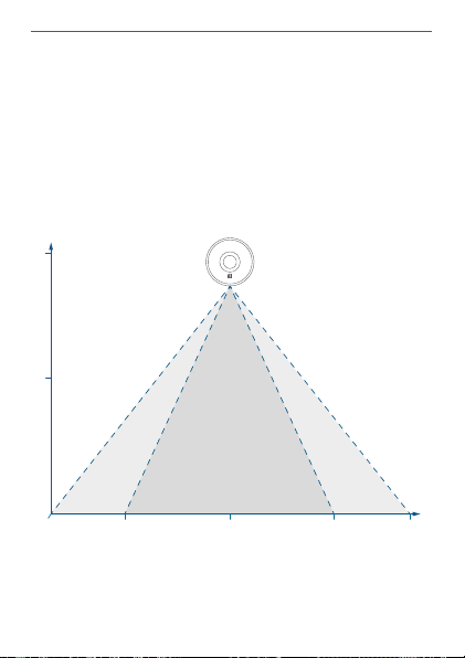
Montagehöhe in m
Erfassungsbereich in m
3,0
1,5
5 Erfassungsbereich
Die leistungsstarke Linse (A) des Präsenzmelders kann
feinste Bewegungen wie bspw. Hand- oder Kopfbewegungen in einem nahen Erfassungsbereich von 3,5 m
zuverlässig erkennen. Im gesamten Erfassungsbereich
werden grobe Bewegungen, wie z. B. das Gehen von Personen erkannt. So lässt sich bei einem Erfassungswinkel
von 105° eine Reichweite von bis zu 7 m erzielen.
weiter
Bereich
0
1,75
naher
Bereich
3,5
weiter
Bereich
5,25
7,0
18
Page 19

Erfassungsbereich
Um den vollen Funktionsumfang des Präsenzmelders (Kleinbewegungserkennung im Nahbereich) nutzen zu können, empfehlen wir eine
Montagehöhe von 3 m nicht zu überschreiten.
Die Verwendung des Geräts ist jedoch nicht auf
eine Montagehöhe von 3 m beschränkt.
Um die Gefahr eines Fehlalarms zu verringern,
sollte das Gerät weder direkter Lichteinstrahlung
durch bspw. Sonnenlicht oder Autoscheinwerfern ausgesetzt, noch in der Nähe einer Wärmequelle (z. B. über einem Heizkörper) montiert
werden.
Die Leistungsfähigkeit der Erfassung hängt von
der Temperaturdi erenz zwischen dem sich bewegenden Objekt und dem jeweiligen Hintergrund ab.
Der Erfassungsbereich sollte auf den Boden ausgerichtet werden, nicht aber direkt auf Fenster,
Heizungen oder sonstige Wärmequellen.
Eine Erfassung durch Glas hindurch ist grundsätzlich nicht möglich. Fehlalarme durch sich bewegende Wärmequellen hinter einem Fenster können aber nicht zu 100 % ausgeschlossen werden.
19
Page 20

Inbetriebnahme
6 Inbetriebnahme
6.1 Installationshinweise
Da der Bus vom Homematic IP Wired Access
Point (HmIPW-DRAP) gespeist wird, müssen Sie
für die Spannungsversorgung des Geräts zunächst einen Homematic IP Wired Access Point
(HmIPW-DRAP) in Betrieb nehmen.
Bitte notieren Sie sich vor der Installation die auf
dem Gerät angebrachte Gerätenummer (SGTIN)
und den Verwendungszweck, damit Sie das Gerät
im Nachhinein leichter zuordnen können. Alternativ steht die Gerätenummer auch auf dem beiliegenden QR-Code-Aufkleber.
Beachten Sie die auf dem Gerät angegebene Abisolierlänge der anzuschließenden Leiter.
Beachten Sie bei der Installation die Gefahrenhinweise gemäß „2 Gefahrenhinweise“ auf Seite 12.
Hinweis! Installation nur durch Personen mit
einschlägigen elektrotechnischen Kenntnissen
und Erfahrungen!*
Durch eine unsachgemäße Installation gefährden Sie
• Ihr eigenes Leben;
• das Leben der Nutzer der elektrischen Anlage.
20
Page 21

Inbetriebnahme
Mit einer unsachgemäßen Installation riskieren Sie
schwere Sachschäden, z. B. durch Brand. Es droht für Sie
die persönliche Haftung bei Personen- und Sachschäden.
Wenden Sie sich an einen Elektroinstallateur!
Erforderliche Fachkenntnisse für die Installation:
*
Für die Installation sind insbesondere folgende Fachkenntnisse erforderlich:
• Die anzuwendenden „5 Sicherheitsregeln“:
Freischalten; gegen Wiedereinschalten sichern;
Spannungsfreiheit feststellen; Erden und Kurzschließen;
benachbarte, unter Spannung stehende Teile abdecken
oder abschranken;
• Auswahl des geeigneten Werkzeuges, der Messgeräte
und ggf. der persönlichen Schutzausrüstung;
• Auswertung der Messergebnisse;
• Auswahl des Elektroinstallationsmaterials zur Sicherstellung der Abschaltbedingungen;
• IP-Schutzarten;
• Einbau des Elektroinstallationsmaterials;
• Art des Versorgungsnetzes (TN-System, IT-System,
TT-System) und die daraus folgenden Anschlussbedingungen (klassische Nullung, Schutzerdung, erforderliche
Zusatzmaßnahmen etc.).
Zugelassene Leitungsquerschnitte zum Anschluss an das
Gerät sind:
Starre Leitung: 0,12-0,50 mm
2
21
Page 22

Inbetriebnahme
Aus Gründen der elektrischen Sicherheit dürfen
zum Anschluss des Homematic IP Wired Bus aus
schließlich folgende Leitungen eingesetzt werden:
• Fernmeldeleitung J-Y(ST)Y mit 2 x 2 x 0,8
(= 0,5mm²) oder 4 x 2 x 0,8 (= 0,5 mm²),
geschirmt, TP
• Ethernet-Verlegekabel S/FUTP, Typ Cat5e oder
höher mit 2 x 2 x AWG22 (= 0,34 mm²) oder
4x2 x AWG22 (= 0,34 mm²), geschirmt, TP
Der Schirm (Begleitdraht) muss am Busanschluss
des Wired Access Points (HmIPW-DRAP) auf “–“
(= Masse) aufgelegt werden. Am Bewegungsmelder darf der Schirm nicht aufgelegt werden.
Achten Sie bei der Auswahl des Montageortes auf
den Verlauf elektrischer Leitungen bzw. auf vorhandene Versorgungsleitungen.
Der Bus wird vom Homematic IP Wired Access
Point (HmIPW-DRAP) gespeist. Weitere Informationen dazu können Sie der Bedienungsanleitung
des Wired Access Points entnehmen.
22
-
Page 23

Inbetriebnahme
6.2 Installation an der Decke
Für die Montage an der Decke gehen Sie wie folgt vor:
• Schalten Sie den entsprechenden Strang des ankommenden Homematic IP Wired Busses ab.
• Wählen Sie die Montageposition, an der Stelle, an
der die Busleitung aus der Decke geführt wird.
• Zeichnen Sie zwei Bohrlöcher (G) in einem Abstand von 40 mm an die Montageposition an (s.
Abbildung 3).
• Bohren Sie die vorgezeichneten Löcher und setzen
Sie die mitgelieferten Dübel ein (s. Abbildung 3).
Bei Steinwänden verwenden Sie einen 5 mm
Bohrer für die Dübel. Bei Holzwänden können Sie
einen 1,5 mm Bohrer verwenden, um das Eindrehen der Schrauben zu erleichtern.
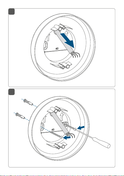
• Führen Sie die Busleitung durch die Kabeldurchführung (F) des Installationsadapters (s. Abbildung 4).
• Montieren Sie den Installationsadapter durch Eindrehen der mitgelieferten Schrauben (3,0 x 30
mm) in die Dübel (s. Abbildung 5).
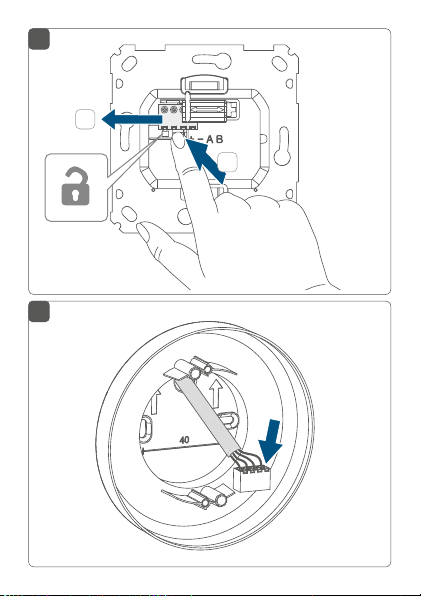
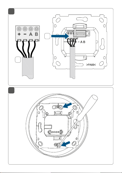
• Um den Anschluss der Busleitung an die Klemmen des Präsenzmelders zu erleichtern, nehmen
Sie die grüne Push-in-Klemme aus dem Gerät
heraus. Dazu drücken Sie die Verriegelung auf
der Rückseite der Montageplatte neben dem
Schloss-Symbol ein und schieben die Klemme
23
Page 24

Inbetriebnahme
zur Seite aus der Montageplatte heraus (s. Abbil-
dung 6).
• Schließen Sie die Busleitung an die Busanschlussklemmen an (s. Abbildung 7+8). Zum Anschließen
und Lösen der einzelnen Adern betätigen Sie den
orangen Betätigungsdrücker mit Hilfe eines kleinen Schraubendrehers.
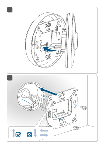
• Setzen Sie die grüne Push-in-Klemme wieder in
die Montageplatte ein (s. Abbildung 8).
• Setzen Sie die Montageplatte auf die Halterungen (H) des Installationsadapters und befestigen
Sie diese anschließend mittels der mitgelieferten
Schrauben (3,2 x 15 mm) (s. Abbildung 9).
• Setzen Sie die Elektronikeinheit des Präsenzmelders in den Installationsadapter ein, indem Sie die
Verbindungsstifte in die dafür vorgesehene Halterung der Montageplatte vollständig einrasten (s.
Abbildung 10).
• Schalten Sie den Homematic IP Wired Bus wieder
ein.
6.3 Installation auf einer Unterputzdose
Für die Installation auf einer Unterputzdose gehen Sie wie
folgt vor:
• Schalten Sie den entsprechenden Strang des ankommenden Homematic IP Wired Busses ab.
• Um den Anschluss der Busleitung an die Klemmen des Präsenzmelders zu erleichtern, nehmen
24
Page 25

Inbetriebnahme
Sie die grüne Push-in-Klemme aus dem Gerät
heraus. Dazu drücken Sie die Verriegelung auf
der Rückseite der Montageplatte neben dem
Schloss-Symbol ein und schieben die Klemme
zur Seite aus der Montageplatte heraus (s. Abbil-
dung 6).
• Schließen Sie die Busleitung an die Busanschlussklemmen an (s. Abbildung 7+8). Zum Anschließen
und Lösen der einzelnen Adern betätigen Sie den
orangen Betätigungsdrücker mit Hilfe eines kleinen Schraubendrehers.
• Setzen Sie die grüne Push-in-Klemme wieder in
die Montageplatte ein (s. Abbildung 8).
• Setzen Sie die Montageplatte (D) in die Unterputzdose und befestigen Sie diese anschließend
mittels der mitgelieferten Schrauben an der Unterputzdose (s. Abbildung 11).
• Setzen Sie die Elektronikeinheit (C) des Präsenzmelders in die Montageplatte ein, indem Sie die
Verbindungsstifte in die dafür vorgesehene Halterung der Montageplatte vollständig einrasten (s.
Abbildung 12).
• Schalten Sie den Homematic IP Wired Bus wieder
ein, um den Anlernmodus des Geräts zu aktivieren (s. „5.4 Anlernen“ auf Seite 19).
25
Page 26

Inbetriebnahme
6.4 Anlernen
Bitte lesen Sie diesen Abschnitt erst vollständig,
bevor Sie mit dem Anlernen beginnen.
Detaillierte Informationen zu den Einrichtungsund Steuerungsmöglichkeiten entnehmen Sie
bitte dem Homematic IP Wired Systemhandbuch.
Damit das Gerät in Ihr System integriert werden und mit
anderen Geräten kommunizieren kann, muss es zunächst
angelernt werden. Sie haben folgende Einrichtungs- und
Steuerungsmöglichkeiten
Anlernen an die Zentrale CCU3
Für eine lokale, softwarebasierte Konfiguration und Steuerung per PC haben Sie die Möglichkeit, das Gerät an die
Zentrale CCU3 anzulernen und in umfangreichen Programmen zu nutzen (s. „6.4.1 Anlernen an die Zentrale
CCU3“ auf Seite 27).
Anlernen an die Homematic IP Cloud
Für eine flexible Steuerung per kostenloser SmartphoneApp können Sie das Gerät
lernen (s. „6.4.1 Anlernen an die Zentrale CCU3“ auf Seite
27). Dabei ist es möglich, die Wired Geräte
• per Smartphone-App über den Homematic IP
Wired Access Point (HmIPW-DRAP) zu steuern
oder
26
:
an die HomematicIP Cloud an-
Page 27

Inbetriebnahme
• mit Homematic IP Funk-Komponenten über den
Homematic IP Access Point (HmIP-HAP) zu kombinieren.
6.4.1 Anlernen an die Zentrale CCU3
Um das HomematicIP Wired Gerät softwarebasiert und
komfortabel steuern und konfigurieren sowie in Zentralenprogrammen nutzen zu können, müssen Sie es an die
WebUI anlernen. Um das Gerät an die Zentrale CCU3 anzulernen, gehen Sie wie folgt vor:
• Richten Sie zunächst Ihre Zentrale CCU3 gemäß
der zugehörigen Bedienungsanleitung ein und ler
nen Sie den Homematic IP Wired Access Point an.
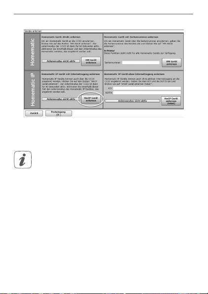
• Starten Sie die Benutzeroberfläche „WebUI“ auf
Ihrem PC.
• Klicken Sie auf den Button „Geräte anlernen“ im
rechten oberen Bereich des Browserfensters.
• Um den Anlernmodus zu aktivieren, klicken Sie
im nächsten Fenster auf „HmIP Gerät anlernen“.
Die Zentrale wird für 60 Sekunden in den Anlernmodus versetzt. Ein Infofeld zeigt die aktuell noch
verbleibende Anlernzeit.
27
-
Page 28
Inbetriebnahme
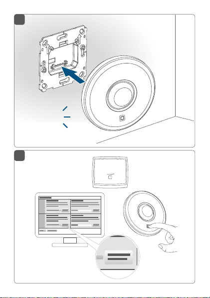
• Nach dem Herstellen der Spannungsversorgung
ist das Gerät für 3 Minuten aktiv.
Sie können den Anlernmodus manuell für weitere
3 Minuten starten, indem Sie die Systemtaste (B)
kurz drücken (s. Abbildung 13).
• Warten Sie, bis der Anlernvorgang abgeschlossen
ist.
• Zur Bestätigung eines erfolgreichen Anlernvorgangs leuchtet die LED (B) grün. Das Gerät ist nun
einsatzbereit.
• Leuchtet die LED rot, versuchen Sie es erneut.
• Nach kurzer Zeit erscheint das neu angelernte
Gerät im Posteingang Ihrer Softwareoberfläche.
28
Page 29

Inbetriebnahme
Neu angelernte Geräte und die zugehörigen Kanäle stehen erst dann für Bedien- und Konfigurationsaufgaben zur
Verfügung, nachdem sie im Posteingang konfiguriert wurden. Weitere Informationen finden Sie im HomematicIP
Wired Systemhandbuch unter www.homematic-ip.com.
Im Betrieb ohne aktiven Internetzugang wählen
Sie die Option „Homematic IP Gerät ohne Inter-
netzugang anlernen“. Geben Sie zum Anlernen
die SGTIN und den Key des Geräts in die entsprechenden Felder ein. Die SGTIN und den Key
finden Sie auf dem beiliegenden Sticker. Bitte bewahren Sie den Sticker sorgfältig auf.
6.4.2 Anlernen an die Homematic IP Cloud per Wired
Access Point (zukünftig geplant)
Wenn Sie Ihre Homematic IP Wired Geräte flexibel per
Smartphone-App steuern möchten, können Sie die
Homematic IP Wired Geräte einfach an die HomematicIP
Cloud anlernen. Gehen Sie dazu wie folgt vor:
• Önen Sie die Homematic IP App auf Ihrem
Smartphone.
• Lernen Sie den Homematic IP Wired Access Point
gemäß der zugehörigen Bedienungsanleitung
über die Smartphone-App an die Homematic IP
Cloud an.
• Wählen Sie den Menüpunkt „Gerät anlernen“ aus.
• Nach dem Herstellen der Spannungsversorgung
29
Page 30

Inbetriebnahme
ist der Anlernmodus des Geräts für 3 Minuten
aktiv.
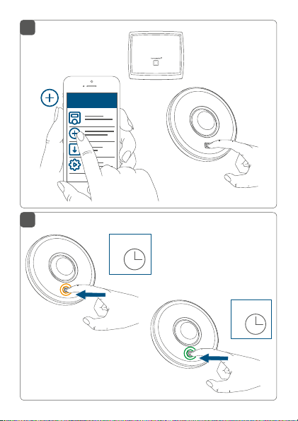
Sie können den Anlernmodus manuell für weitere
3 Minuten starten, indem Sie die Systemtaste (B)
kurz drücken (s. Abbildung 14).
• Das Gerät erscheint automatisch in der Homematic IP App.
• Zur Bestätigung geben Sie in der App die letzten
vier Ziern der Gerätenummer (SGTIN) ein oder
scannen Sie den QR-Code. Die Gerätenummer
finden Sie auf dem Aufkleber im Lieferumfang
oder direkt am Gerät.
• Warten Sie, bis der Anlernvorgang abgeschlossen
ist.
• Zur Bestätigung eines erfolgreichen Anlernvorgangs leuchtet die LED (B) grün. Das Gerät ist nun
einsatzbereit.
• Leuchtet die LED rot, versuchen Sie es erneut.
• Wählen Sie die gewünschte Lösung für Ihr Gerät
aus.
• Vergeben Sie in der App einen Namen für das Gerät und ordnen Sie es einem Raum zu.
30
Page 31

Funktionstest
Wenn Sie bereits Homematic IP Geräte im SmartHome-System nutzen oder Ihre Wired Geräte mit
Funk-Komponenten von Homematic IP kombinieren möchten, können Sie die Homematic IP
Wired Geräte auch einfach an einen (bestehen
den) Homematic IP Access Point anlernen. Lernen
Sie dazu den Homematic IP Wired Access Point
gemäß der zugehörigen Bedienungsanleitung an
den (bestehenden) Homematic IP Access Point
an. Anschließend gehen Sie wie oben beschrieben
vor, um den Präsenzmelder anzulernen.
7 Funktionstest
Der Funktionstest wird nur aktiviert, wenn der
Präsenzmelder bereits angelernt wurde.
Der Funktionstest kann zusätzlich über die
Homematic IP App aktiviert werden.
Bis 10 Minuten nach dem Anlernen oder nach dem Herstellen der Spannungsversorgung (wenn das Gerät bereits
angelernt ist) signalisiert die Geräte-LED (B) erkannte Bewegungen. Die LED blinkt bei jeder erkannten Bewegung
grün auf. Auf diese Weise lassen sich der Erfassungsbereich und die Empfindlichkeit direkt am Sensor überprüfen.
-
31
Page 32

Fehlercodes und Blinkfolgen
8 Fehlercodes und Blinkfolgen
Blinkcode Bedeutung Lösung
Kurzes
oranges
Blinken
1x langes
grünes
Leuchten
1x langes
rotes
Leuchten
Kurzes
oranges
Blinken
(alle 10 s)
Grünes
Blinken
(jeweils
für eine
Sekunde)
6x langes
rotes Blinken
32
Datenübertragung
Vorgang
bestätigt
Vorgang
fehlgeschlagen
Anlernmodus
aktiv
Funktionstest Warten Sie, bis der
Gerät defekt Achten Sie auf die
Warten Sie, bis die
Übertragung beendet ist.
Sie können mit der
Bedienung fortfahren.
Versuchen Sie es
erneut.
Geben Sie die letzten vier Ziern der
GeräteSeriennummer zur
Bestätigung ein (s.
„6.4 Anlernen“ auf
Seite 26).
Funktionstest nach
10 Minuten vorüber
ist (s. „7 Funktionstest“ auf Seite 31).
Anzeige in Ihrer App
oder wenden Sie
sich an Ihren Fachhändler.
Page 33

Wiederherstellung der Werkseinstellungen
1x oranges
und 1x
grünes
Leuchten (nach
Spannungszufuhr)
Testanzeige Nachdem die Test-
anzeige
erloschen ist,
können Sie fortfahren.
9 Wiederherstellung der
Werkseinstellungen
Die Werkseinstellungen des Geräts können wiederhergestellt werden. Dabei gehen alle Einstellungen verloren.
Um die Werkseinstellungen des Geräts wiederherzustellen, gehen Sie wie folgt vor:
• Drücken Sie für 4 s auf die Systemtaste (B), bis
die LED (B) schnell orange zu blinken beginnt (s.
Abbildung 14).
• Lassen Sie die Systemtaste wieder los.
• Drücken Sie die Systemtaste erneut für 4 s, bis die
LED grün aufleuchtet (s. Abbildung 14).
• Lassen Sie die Systemtaste wieder los, um das
Wiederherstellen der Werkseinstellungen abzuschließen.
33
Page 34

Wartung und Reinigung
Das Gerät führt einen Neustart durch. Nach dem Neustart
können Sie das Gerät wieder in Ihr Homematic IP System
integrieren.
10 Wartung und Reinigung
Das Gerät ist wartungsfrei. Überlassen Sie eine
Reparatur einer Fachkraft.
Reinigen Sie das Gerät mit einem weichen, sauberen,
trockenen und fusselfreien Tuch. Verwenden Sie keine
lösemittelhaltigen Reinigungsmittel, das Kunststogehäuse und die Beschriftung können dadurch angegrien
werden.
11 Technische Daten
Geräte-Kurzbezeichnung:
Versorgungsspannung: 24 VDC, +5 % -20 %, SELV
Stromaufnahme: 5 mA max.
Leistungsaufnahme im
Ruhebetrieb: 45,6 mW (1,9 mA)
Leitungsart u. -querschnitt: Starre Leitung
0,12-0,50 mm²
Installation: nur in Schalterdosen
34
HmIPW-SPI
(Gerätedosen) gemäß DIN
49073-1 oder im Installationsadapter
Page 35

Technische Daten
Schutzart: IP20
Schutzklasse: III
Umgebungstemperatur: -5 bis +40 °C
Abmessungen (Ø x H): 100 x 45 mm
Gewicht: 92 g
Erfassungsreichweite: 7 m
Erfassungswinkel: 105°
Technische Änderungen vorbehalten.
Entsorgungshinweis
Gerät nicht im Hausmüll entsorgen! Elektronische Geräte sind entsprechend der Richtlinie
über Elektro- und Elektronik-Altgeräte über die
örtlichen Sammelstellen für Elektronik-Altgeräte
zu entsorgen.
Konformitätshinweis
Das CE-Zeichen ist ein Freiverkehrszeichen, das
sich ausschließlich an die Behörden wendet und
keine Zusicherung von Eigenschaften beinhaltet.
Bei technischen Fragen zum Gerät wenden Sie
sich bitte an Ihren Fachhändler.
35
Page 36

Package contents
Quantity Description
1 Homematic IP Wired Presence Sensor –
1 Mounting plate
1 Installation adapter for ceiling mounting
2 Plugs 5 mm
2 Screws 3.0 x 30 mm
4 Screws 3.2 x 15 mm
2 Screws 3.2 x 25 mm
2 Operating manuals
1 Additional safety instructions
Documentation © 2019 eQ-3 AG, Germany
All rights reserved. Translation from the original version in German. This manual may not be reproduced in any format, either in
whole or in part, nor may it be duplicated or edited by electronic,
mechanical or chemical means, without the written consent of
the publisher.
Typographical and printing errors cannot be excluded. However,
the information contained in this manual is reviewed on a regular
basis and any necessary corrections will be implemented in the
next edition. We accept no liability for technical or typographical
errors or the consequences thereof.
All trademarks and industrial property rights are acknowledged.
Printed in Hong Kong
Changes may be made without prior notice as a result of technical advances.
154135 (web)
Version 1.0 (08/2019)
36
indoor
Page 37

Table of contents
1 Information about this manual....................................38
2 Hazard information ........................................................38
3 Function and device overview ....................................41
4 General system information ........................................42
5 Detection range ..............................................................43
6 Start-up ............................................................................45
6.1 Installation instructions ..................................................... 45
6.2 Ceiling installation .............................................................. 48
6.3 Installation on a flush-mounted box .............................. 49
6.4 Teaching-in .......................................................................... 50
6.4.1 Connecting to the Central Control Unit
CCU3 .........................................................................51
6.4.2 Connecting to the Homematic IP cloud using
the Wired Access Point (available soon) ........... 54
7 Function test ................................................................... 55
8 Error codes and flashing sequences ..........................56
9 Restore factory settings ................................................57
10 Maintenance and cleaning ...........................................58
11 Technical specifications ................................................58
37
Page 38

Information about this manual
1 Information about this manual
Please read this manual carefully before beginning operation with your Homematic IP components. Keep the
manual so you can refer to it at a later date if you need to.
If you hand over the device to other persons for use,
please hand over this manual as well.
Symbols used:
Attention!
This indicates a hazard.
Please note:
This section contains important additional information.
2 Hazard information
Do not open the device. It does not contain any
parts that can be maintained by the user. If you
have any doubts, have the device checked by an
expert.
For safety and licensing reasons (CE), unauthorized change and/or modification of the device is
not permitted.
38
Page 39

Hazard information
Do not use the device if there are signs of damage to the housing, control elements or connecting sockets, for example. If you have any doubts,
have the device checked by an expert.
The device may only be operated indoors and
must be protected from the eects of moisture,
vibrations, solar or other methods of heat radiation, cold and mechanical loads.
The device is not a toy; do not allow children to
play with it. Do not leave packaging material lying
around. Plastic films/bags, pieces of polystyrene,
etc. can be dangerous in the hands of a child.
We do not assume any liability for damage to
property or personal injury caused by improper
use or the failure to observe the hazard information. In such cases, any claim under warranty is
extinguished! For consequential damages, we assume no liability!
When connecting to the device terminals, take
the permissible cables and cable cross sections
into account.
Observe the installation instructions for installation in distribution systems (DINVDE0100-410).
39
Page 40

Hazard information
The device is part of the building installation. Observe the relevant national standards and directives during planning and set-up. The device is
intended for operation within the Homematic IP
Wired bus only. The Homematic IP Wired bus is a
SELV power circuit. Common cable routing of
power supply and the Homematic IP Wired bus in
installation or junction boxes is not permitted.
The required isolation for power supply of the
building installation to the Homematic IP Wired
bus must be observed at all times. Non-compliance with the installation instructions can cause
fire or introduce other hazards.
The device may only be used for fixed installations. The device must be securely attached within a fixed installation.
Using the device for any purpose other than that
described in this operating manual does not fall
within the scope of intended use and shall invalidate any warranty or liability.
The device may only be operated within domestic environment, in business and trade areas as
well as in small enterprises.
40
Page 41

Function and device overview
3 Function and device overview
The Homematic IP Wired Presence Sensor reliably recognizes if someone is present by detecting even smallest
movements as well as light intensity. The sensor is able to
detect large movements (e.g. people walking) in a wide
range as well as smallest movements (e.g. hand movements on a keyboard) in nearby surroundings.
The high-performance presence sensor can be used
for light control or security applications, for example.
In connection with other Homematic IP Wired devices,
lights can be switched on or an alarm can be triggered
if a person is present in a room and motion detection is
detected.
Thanks to the detection range of up to 7 m (at a mounting
height of 2.7 m) and a detection angle of 105 °, the
presence sensor can be optimised to the particular
surroundings. The device is easily integrated into a flushmounted box or mounted at any place on the ceiling.
High room temperatures (e.g. when using a floor heating
system) can influence the sensitivity level of presence
sensors. The presence sensor automatically compensates
temperature influences in order to ensure precise motion
detection at any time.
41
Page 42

General system information
Device overview (see figure 1):
(A) Lens
(B) System button (teach-in button and LED)
(C) Electronic unit (presence sensor)
(D) Mounting plate
(E) Connecting terminals (push-in terminal)
Overview installation adapter (see figure 2):
(F) Cable bushing
(G) Bore holes
(H) Brackets
Mounting holes for wired installation adapter
(I)
4 General system information
This device is part of the Homematic IP smart home
system and works with the Homematic IP protocol. All
devices of the system can be configured comfortably and
individually with the user interface of the Central Control
Unit CCU3 or flexibly via the Homematic IP smartphone
app in connection with the Homematic IP cloud (available
soon). All available functions provided by the system in
combination with other components are described in
the Homematic IP Wired Installation Guide. All current
technical documents and updates are provided at
www.eQ-3.com.
42
Page 43

Detection range
mounting height in m
detection range in m
3,0
1,75
1,5
7,0
3,5
5 Detection range
The powerful lens (A) can reliably detect smallest
movements, like a hand or head movement, within a
close detection range of 3.5 m. Larger movements,
like if people are walking, can be detected in the entire
detection range. With a detection angle of 105°, a range
of up to 7 m is achieved.
wide
range
0
close
range
wide
range
5,25
43
Page 44

Detection range
To enable the entire scope of functions of the
presence sensor (smallest movements in the
close range) we recommend to not exceed a
mounting height of 3 m. However, operation of
the device is not limited to a mounting height of
3 m.
To reduce the risk of a false alarm being triggered,
the device must not be exposed to incident light
e.g. caused by sunlight or car headlights, nor
must it be mounted in the vicinity of a heat source
(above a radiator, for example).
The eectiveness of the detection procedure depends on the temperature dierence between
the moving object and the relevant background.
The detection range should be aligned to the
floor, but not directly to a window, radiator or
other heat source.
In general, it is not possible to detect motion
through glass. False alarms caused by moving
heat sources behind a window cannot be excluded by 100 %.
44
Page 45

6 Start-up
6.1 Installation instructions
Since the bus is powered by the Homematic IP
Wired Access Point (HmIPW-DRAP), you must
first set-up a Homematic IP Wired Access Point
(HmIPW-DRAP) to enable power supply for the
device.
Before installation, please note the device number (SGTIN) labelled on the device as well as the
exact application purpose in order to make later
allocation easier. You can also find the device
number on the QR code sticker supplied.
Start-up
Please note the insulation stripping length of the
conductor to be connected, indicated on the de
vice.
Please observe the hazard information in section
“2 Hazard information” on page 38 during in
stallation.
Please note! Only to be installed by persons with
the relevant electro-technical knowledge and
experience!*
45
-
-
Page 46

Start-up
Incorrect installation can put
• your own life at risk;
• and the lives of other users of the electrical system.
Incorrect installation also means that you are running the
risk of serious damage to property, e.g. because of a fire.
You may be personally liable in the event of injuries or
damage to property.
Contact an electrical installer!
*Specialist knowledge required for installation:
The following specialist knowledge is particularly important during
installation:
• The “5 safety rules” to be used:
Disconnect from mains; Safeguard from switching on
again; Check that system is de-energised; Earth and
short circuit; Cover or cordon o neighbouring live parts;
• Select suitable tool, measuring equipment and, if necessary, personal safety equipment;
• Evaluation of measuring results;
• Selection of electrical installation material for safeguarding shut-o conditions;
• IP protection types;
• Installation of electrical installation material;
• Type of supply network (TN system, IT system, TT system) and the resulting connecting conditions (classical
zero balancing, protective earthing, required additional
measures etc.).
46
Page 47

Start-up
Permitted cable cross sections for connecting to the device are:
Rigid cable: 0.12-0.50 mm
2
For reasons of electrical safety, only the following
cables must be used for connecting to the Home
matic IP wired bus:
• Telephone cable J-Y(ST)Y with 2 x 2 x 0.8
(= 0.5mm²) or 4 x 2 x 0.8 (= 0.5 mm²),
shielded, TP
• Ethernet installation cable S/FUTP, Type Cat5e or
higher with 2 x 2 x AWG22 (= 0.34 mm²) or
4 x 2 x AWG22 (= 0.34 mm²), shielded, TP
The shield (continuity wire) must be connected to
“–” (=GND) at the bus connection of the Wired
Access Point (HmIPW-DRAP). The shield may not
be connected to the presence sensor.
When selecting the installation location, check
for electrical wires and power supply cables.
The bus is powered by the Homematic IP Wired
Access Point (HmIPW-DRAP). For further information, please refer to the operating manual of
the corresponding Wired Access Points.
-
47
Page 48

Start-up
6.2 Ceiling installation
For the installation on the ceiling, please proceed as follows:
• Disconnect the corresponding line of the
incoming Homematic IP wired bus.
• Select a mounting location at that point where
the bus cable is led out of the ceiling.
• Mark the two bore holes (G) to the mounting
location in a distance of 40 mm (see fig. 3).
• Drill the holes marked and insert the supplied
plugs (see figure 3).
If you are working with a stone wall, drill the
marked two 5 mm holes and insert the plugs
supplied. If you are working with a wooden wall,
you can pre-drill 1.5 mm holes to make screws
easier to insert.
• Feed the bus cable through the cable bushing (F)
of the installation adapter (see figure 4).
• Mount the installation adapter by screwing the
supplied screws (3.0 x 30 mm) into the plugs (see
figure 5).
• To facilitate the connection of the bus line to the
terminals of the presence sensor, remove the
green push-in terminal from the device. Press the
latch on the back of the mounting plate next to
the lock symbol and slide the clamp out of the
48
Page 49

Start-up
mounting plate to the side (figure 6).
• Connect the bus line to the bus connecting
terminals (see figure 7+8). To connect and loosen
the single wires, press the orange clamp using a
small screwdriver.
• Put the green push-in terminal back into the
mounting plate (see figure 8).
• Place the mounting plate on the brackets (H)
of the installation adapter and then fasten them
using the screws (3.2 x 15 mm) supplied (see
figure 9).
• Place the electronic unit of presence sensor into
the installation adapter by fully snapping the connection pins into the appropriate bracket of the
mounting plate (see figure 10).
• Switch the Homematic IP Wired bus on again.
6.3 Installation on a flush-mounted box
For installation on a flush-mounting box, please proceed
as follows:
• Disconnect the corresponding line of the incoming Homematic IP wired bus.
• To facilitate the connection of the bus line to the
terminals of the presence sensor, remove the
green push-in terminal from the device. Press the
latch on the back of the mounting plate next to
the lock symbol and slide the clamp out of the
mounting plate to the side (figure 6).
49
Page 50

Start-up
• Connect the bus line to the bus connecting terminals (see figure 7+8). To connect and loosen
the single wires, press the orange clamp using a
small screwdriver.
• Put the green push-in terminal back into the
mounting plate (see figure 8).
• Place the mounting plate (D) in the flushmounted box and fasten it to the flush-mounted
box using the screws supplied (see figure 11).
• Place the electronic unit (C) of the presence sensor into the mounting plate by fully snapping the
connection pins into the appropriate bracket of
the mounting plate (see figure 12).
• Switch the Homematic IP wired bus on again to
activate the teach-in mode of the device (see “6.4
Teaching-in” on page 50).
6.4 Teaching-in
Please read this entire section before starting
the teach-in procedure.
Please refer to the Homematic IP Wired System
Manual for detailed information on setup and
control options.
To integrate the device into your system and enable it to
communicate with other devices, you must teach it in first.
You can use the following set-up and control options
50
:
Page 51

Start-up
Connecting to the Homematic IP Central Control Unit
CCU3
For local, software-based configuration and control via
PC, you can connect the presence sensor to a Central
Control Unit CCU3 and to use it in comprehensive programs (see “6.4.1 Connecting to the Central Control Unit
CCU3” on page 51).
Connection to the Homematic IP cloud
For a flexible control via free smartphone app, connect the device
to the Homematic IP cloud (see “6.4.1
Connecting to the Central Control Unit CCU3” on page
51). You can
• control the wired system via smartphone app
using the Homematic IP Wired Access Point
(HmIPW-DRAP) or
• combine wired devices with wireless Homematic
IP devices via the Homematic IP Access Point
(HmIP-HAP).
6.4.1 Connecting to the Central Control Unit CCU3
To control and configure Homematic IP wired devices
software-based and comfortably as well as use it in central control unit programs, you have to connect it to to
the WebUI. To connect the device to the Central Control
Unit CCU3, proceed as follows:
• Set up your Central Control Unit CCU3 as described in the operating manual and connect the
51
Page 52

Start-up
Homematic IP Wired Access Point.
• Start the user interface “WebUI” on your computer.
• Click the “Teach-in devices” button on the righthand side of the screen.
• To activate teach-in mode, click “Teach-in HmIP
device” in the next window. The teach-in mode
of the Central Control Unit will be activated for
60 seconds. An information box shows how
much teach-in time remains.
52
Page 53

Start-up
• After power supply is established, the device will
be active for 3 minutes.
You can manually start the teach-in mode for another 3 minutes by pressing the system button (B)
shortly (see figure 13).
• Please wait until teach-in is completed.
• If teaching-in was successful, the LED (B) lights
up green. The device is now ready for use.
• If the LED lights up red, please try again.
• After a short time, the newly connected device
appears in the inbox of your software interface.
Newly connected devices and the corresponding channels
are ready for operation and configuration only after they
have been configured in the inbox. You will find further information in the Homematic IP Wired Installation Guide,
available for download at www.homematic-ip.com.
For operation without Internet connection,
please select the option “Teaching-in of Home-
matic IP device without Internet connection”.
Please enter the SGTIN and key of the device into
the corresponding fields. You will find the SGTIN
and the key on the supplied sticker. Please keep
the sticker in safe place.
53
Page 54

Start-up
6.4.2 Connecting to the Homematic IP cloud using
the Wired Access Point (available soon)
If you want to control your Homematic IP Wired devices
flexibly via smartphone app, they can be connected to
the Homematic IP cloud. To do this, please proceed as
follows:
• Open the Homematic IP app on your smartphone.
• Connect the Homematic IP Wired Access Point via
the smartphone app to the Homematic IP cloud,
as described in the corresponding user manual
• Select the menu item “Teach-in device”.
• After power supply is established, the teach-in
mode will be active for 3 minutes.
You can manually start the teach-in mode for another 3 minutes by pressing the system button (B)
shortly (see figure 14).
• Your device will automatically appear in the
Homematic IP app.
• To confirm, please enter the last four digits of the
device number (SGTIN) in your app or scan the
QR code. Therefore, please see the sticker supplied or attached to the device.
• Please wait until teach-in is completed.
• If teaching-in was successful, the LED (B) lights
up green. The device is now ready for use.
• If the LED lights up red, please try again.
54
Page 55

Function test
• Select the desired solution for your device.
• In the app, give the device a name and allocate
it to a room.
If you are already using Homematic IP devices in
your smart home system or if you want to combine
your Homematic IP wired devices with wireless
Homematic IP components, you can also connect
the Homematic IP wired devices to an (installed)
Access Point. Therefore, connect the Homemat
icIP Wired Access Point to the (already installed)
Homematic IP Access Point, as described in the
user manual. Afterwards, please proceed as de
scribed above to connect the presence sensor.
-
-
7 Function test
The function test is only activated if the presence
sensor has already been connected.
The function test can be activated via the Homematic IP app
Up to 10 minutes after connecting the device or
establishing the power supply (if the device has already
been connected), the device LED (B) indicates detected
movements. The LED flashes green with every movement
detected. In this way, the detection range and sensitivity
can be checked directly on the device.
55
Page 56

Error codes and flashing sequences
8 Error codes and flashing
sequences
Flashing code Meaning Solution
Short orange
flashing
1x long green
lighting
1x long red
lighting
Short orange
flashing
(every 10
seconds)
Green flashing
(for one
second each)
6x long red
flashing
56
Data transfer Wait until the
Operation
confirmed
Operation
failed
Teach-in mode
active
Functional test Please wait until the
Device
defective
transmission is
completed.
You can continue
operation.
Please try again.
Please enter the
last four numbers
of the device
serial number for
confirmation (see
“6.4 Teaching-in”
on page 50).
function test has
finished after 10
minutes (see sec.
“7 Function test” on
page 55).
Please see your
app for error message or contact
your retailer.
Page 57

Restore factory settings
1x orange
and 1x green
lighting (after
establishing
power supply)
Test display After the test dis-
play has stopped,
you can continue.
9 Restore factory settings
The factory settings of the device can be restored.
If you do this, you will lose all your settings.
To restore the factory settings of the device, please
proceed as follows:
• Press and hold down the system button (B) until the
LED (B) quickly starts flashing orange (see fig. 14).
• Release the system button again.
• Press and hold down the system button again for
4 seconds, until the LED lights up green (see fig-
ure 14).
• Release the system button to finish the procedure.
The device will perform a restart. After the restart, you
can again integrate your device into your Homematic IP
system.
57
Page 58

Maintenance and cleaning
10 Maintenance and cleaning
The product does not require any maintenance.
Enlist the help of an expert to carry out any
repairs.
Clean the device using a soft, lint-free cloth that is clean
and dry. Do not use any detergents containing solvents,
as they could corrode the plastic housing and label.
11 Technical specifications
Device short name:
Supply voltage: 24 VDC, +5 % -20 %, SELV
Current consumption: 5 mA max.
Standby power consumption: 45.6 mW (1.9 mA)
Cable type and cross section Rigid cable
0.12-0.50 mm²
Installation: only in normal commer-
Degree of protection: IP20
Protection class: III
Ambient temperature: -5 to +40 °C
Dimensions (ø x H) 100 x 45 mm
Weight: 92 g
58
HmIPW-SPI
cial switch boxes (device
boxes) in accordance
with DIN 49073-1 or in
the installation adapter.
Page 59

Technical specifications
Detection range: 7 m
Detection angle: 105°
Subject to modifications.
Instructions for disposal
Do not dispose of the device with regular domestic waste! Electronic equipment must be disposed of at local collection points for waste electronic equipment in compliance with the Waste
Electrical and Electronic Equipment Directive.
Information about conformity
The CE sign is a free trading sign addressed exclusively to the authorities and does not include
any warranty of any properties.
For technical support, please contact your specialist dealer.
59
Page 60

Bevollmächtigter des Herstellers:
Manufacturer’s authorised representative:
eQ-3 AG
Maiburger Straße 29
26789 Leer / GERMANY
www.eQ-3.de
 Loading...