

Page 1
Installations- und
Bedienungsanleitung
Installation instruction and
operating manual
Wired Eingangsmodul – 32-fach S. 2
Wired Input Module – 32 channels p. 31
HmIPW-DRI32
Page 2

Lieferumfang
Anzahl Bezeichnung
1 Homematic IP Wired Eingangsmodul –
1 Bus-Verbindungskabel
1 Bus-Blindstopfen
1 Bedienungsanleitung
Dokumentation © 2018 eQ-3 AG, Deutschland
Alle Rechte vorbehalten. Ohne schriftliche Zustimmung des
Herausgebers darf diese Anleitung auch nicht auszugsweise in
irgendeiner Form reproduziert werden oder unter Verwendung
elektronischer, mechanischer oder chemischer Verfahren vervielfältigt oder verarbeitet werden.
Es ist möglich, dass die vorliegende Anleitung noch drucktechnische Mängel oder Druckfehler aufweist. Die Angaben in dieser
Anleitung werden jedoch regelmäßig überprüft und Korrekturen
in der nächsten Ausgabe vorgenommen. Für Fehler technischer
oder drucktechnischer Art und ihre Folgen übernehmen wir keine
Haftung.
Alle Warenzeichen und Schutzrechte werden anerkannt.
Printed in Hong Kong
Änderungen im Sinne des technischen Fortschritts können ohne
Vorankündigung vorgenommen werden.
151693 (web)
Version 2.0 (06/2018)
32-fach
Page 3
1
H
G
A
°C
B
C
G
EDF
H
RX
TX
V
Page 4
2
Page 5
3
4
Page 6
5
7
6
Page 7

Inhaltsverzeichnis
1 Hinweise zur Anleitung ...................................................8
2 Gefahrenhinweise ............................................................8
3 Funktion und Geräteübersicht ....................................12
4 Allgemeine Systeminformationen ..............................14
5 Inbetriebnahme .............................................................. 14
5.1 Installationshinweise ...........................................................14
5.2 Auswahl der Spannungsversorgung ................................ 17
5.3 Montage und Installation ...................................................18
5.4 Anlernen ...............................................................................20
5.4.1 Anlernen an die Zentrale CCU3 ...........................21
5.4.2 Anlernen an die Homematic IP Cloud per
Wired Access Point ................................................ 23
6 Bedienung ........................................................................25
7 Fehlercodes und Blinkfolgen ....................................... 27
8 Wiederherstellung der Werkseinstellungen ..............28
9 Wartung und Reinigung ................................................29
10 Technische Daten ..........................................................29
7
Page 8
Hinweise zur Anleitung
1 Hinweise zur Anleitung
Lesen Sie diese Anleitung sorgfältig, bevor Sie Ihr Homematic IP Wired Gerät in Betrieb nehmen. Bewahren Sie
die Anleitung zum späteren Nachschlagen auf!
Wenn Sie das Gerät anderen Personen zur Nutzung überlassen, übergeben Sie auch diese Anleitung.
Benutzte Symbole:
Achtung!
Hier wird auf eine Gefahr hingewiesen.
Hinweis. Dieser Abschnitt enthält zusätzliche
wichtige Informationen.
2 Gefahrenhinweise
Önen Sie das Gerät nicht. Es enthält keine durch
den Anwender zu wartenden Teile. Das Önen
birgt die Gefahr eines Stromschlages. Lassen Sie
das Gerät im Fehlerfall von einer Fachkraft prüfen.
Aus Sicherheits- und Zulassungsgründen (CE) ist
das eigenmächtige Umbauen und/oder Verändern des Geräts nicht gestattet.
8
Page 9
Gefahrenhinweise
Verwenden Sie das Gerät nicht, wenn es von außen erkennbare Schäden, z. B. am Gehäuse, an
Bedienelementen oder an den Anschlussbuchsen
ausweist. Lassen Sie das Gerät im Zweifelsfall von
einer Fachkraft prüfen.
Betreiben Sie das Gerät nur in trockener sowie
staubfreier Umgebung, setzen Sie es keinem Einfluss von Feuchtigkeit, Vibrationen, ständiger
Sonnen- oder anderer Wärmeeinstrahlung, Kälte
und keinen mechanischen Belastungen aus.
Das Gerät ist kein Spielzeug! Erlauben Sie Kindern
nicht damit zu spielen. Lassen Sie das Verpackungsmaterial nicht achtlos liegen. Plastikfolien/
-tüten, Styroporteile etc. können für Kinder zu
einem gefährlichen Spielzeug werden.
Bei Sach- oder Personenschäden, die durch unsachgemäße Handhabung oder Nichtbeachten
der Gefahrenhinweise verursacht werden, übernehmen wir keine Haftung. In solchen Fällen erlischt jeder Gewährleistungsanspruch! Für Folgeschäden übernehmen wir keine Haftung!
9
Page 10
Gefahrenhinweise
Das Eingangsmodul ist Teil der Gebäudeinstallation. Bei der Planung und Errichtung sind die einschlägigen Normen und Richtlinien des Landes
zu beachten. Das Eingangsmodul ist ausschließlich für den Betrieb am Homematic IP Wired Bus
vorgesehen. Der Homematic IP Wired Bus ist ein
SELV-Stromkreis. Die Netzspannung der Gebäudeinstallation und der Homematic IP Wired
Bus sind getrennt zu führen. Eine gemeinsame
Führung einer Netzspannung und des Homematic IP Wired Bus in Installations- und Verteilerdosen ist nicht zulässig. Die notwendige Isolation
einer Netzspannung der Hausinstallation zum
Homematic IP Wired Bus ist immer einzuhalten.
Bei Nichtbeachtung der Installationshinweise
können Brand oder andere Gefahren entstehen.
Für den sicheren Betrieb muss das Gerät in einen
Stromkreisverteiler entsprechend VDE 0603, DIN
43871 (Niederspannungsunterverteilung (NSUV)),
DIN 18015-x eingebaut werden. Die Montage muss
auf einer Tragschiene (Hutschiene, DIN-Rail) lt.
60715 erfolgen. Installation und Verdrahtung
EN
sind entsprechend VDE 0100 (VDE 0100-410, VDE
0100-510 usw.) durchzuführen. Es sind die Vor
schriften der Technischen Anschlussbestimmungen
(TAB) des Energieversorgers zu berücksichtigen.
10
-
Page 11
Gefahrenhinweise
Beachten Sie beim Anschluss an die Geräteklemmen die hierfür zulässigen Leitungen und Leitungsquerschnitte.
Vor Einbau und Anschluss des Gerätes freischalten und spannungsführende Teile in der Umgebung abdecken.
Das Gerät ist nur für den Einsatz in Wohnbereichen, Geschäfts- und Gewerbebereichen sowie
in Kleinbetrieben bestimmt.
Bei Einsatz in einer Sicherheitsanwendung ist das
Gerät/System in Verbindung mit einer USV (unter
brechungsfreie Stromversorgung) zu betreiben,
um einen möglichen Netzausfall zu überbrücken.
Jeder andere Einsatz, als der in dieser Bedienungsanleitung beschriebene, ist nicht bestimmungsgemäß und führt zu Gewährleistungs- und
Haftungsausschluss.
11
-
Page 12

Funktion und Geräteübersicht
3 Funktion und Geräteübersicht
Das Homematic IP Wired Eingangsmodul – 32-fach lässt
sich einfach auf einer Hutschiene in einem Stromkreisverteiler montieren. Über 32 Eingänge können mehrere
Schalter und Taster angeschlossen werden. Dies ermöglicht das Schalten oder Dimmen von Lampen oder anderen Beleuchtungsanlagen über angelernte Homematic IP
Wired Schalt- oder Dimmaktoren.
Darüber hinaus haben Sie die Möglichkeit, einzelne Eingänge des Eingangsmoduls als Sensor-Eingänge zu konfigurieren, um z. B. Öner- oder Schließerkontakte zu
überwachen.
Das Eingangsmodul verfügt über eine Sonderfunktion für den Einsatz von Netzspannungstastern
oder -schaltern. Um dem Korrodieren und mögli
chen Funktionseinschränkungen der Taster bzw.
Schalter vorzubeugen, kann für jeden Eingang ein
„Korrosionsschutz“ aktiviert werden. Dieser sorgt
dafür, dass kurzzeitig ein erhöhter Strom durch den
Taster oder Schalter fließt, wenn er betätigt wird.
Der Stromimpuls wirkt der Korrosion entgegen. Die
Funktion ist werksseitig deaktiviert und lässt sich für
jeden Kanal separat einschalten.
12
-
Page 13
Geräteübersicht (s. Abbildung 1):
EDF
°C
B
C
G
G
H
H
EDF
°C
B
C
G
G
H
H
RX
1 1
RX
TX
1 1
V
(A) Systemtaste (Anlerntaste und LED)
(B) Channel-Taste
(C) Select-Taste
(D) LC-Display
Busanschluss 1
(E)
(F) Busanschluss 2
(G) Eingangsklemmen
(H) Masseklemmen (GND)
Displayübersicht (s. Abbildung 1):
Symbol Bedeutung
Eingang nicht betätigt
Eingang betätigt
Daten werden vom Bus empfangen
Daten werden zum Bus gesendet
Temperaturangabe (eingeschaltet, wenn
Temperatur angezeigt wird)
Spannungsangabe (eingeschaltet, wenn
Spannung angezeigt wird)
Funktion und Geräteübersicht
13
Page 14
Allgemeine Systeminformationen
4 Allgemeine Systeminformationen
Dieses Gerät ist Teil des Homematic IP Smart-HomeSystems und kommuniziert über das HomematicIP Pro
tokoll. Sie haben die Möglichkeit, alle Geräte des Systems
komfortabel und individuell über die Bedienoberfläche
der Zentrale CCU3 oder flexibel per Smartphone über
die HomematicIP App in Verbindung mit der Homema
tic IP Cloud zu konfigurieren. Welcher Funktionsumfang
sich innerhalb des Systems im Zusammenspiel mit wei
teren Komponenten ergibt, entnehmen Sie bitte dem
HomematicIP Wired Systemhandbuch. Alle technischen
Dokumente und Updates finden Sie stets aktuell unter
www.eQ-3.de.
5 Inbetriebnahme
5.1 Installationshinweise
Beachten Sie bei der Installation die Gefahrenhinweise gemäß „2 Gefahrenhinweise“ auf Seite 2.
Beachten Sie die auf dem Gerät angegebene Abisolierlänge der anzuschließenden Leiter.
Die Eingänge sind nicht spannungsfrei sondern
stellen die Busspannung zur Verfügung. Angeschlossene Taster, Schalter oder sonstige Schaltelemente müssen für eine Nennspannung von
mind. 26 V spezifiziert sein.
14
-
-
-
Page 15
Inbetriebnahme
Aus Gründen der elektrischen Sicherheit darf zum
Anschluss des Homematic IP Wired Bus ausschließlich das mitgelieferte Homematic IP Wired
Buskabel oder ein als Zubehör erhältliches eQ-3
Homematic IP Wired Buskabel anderer Länge
verwendet werden.
Starre Leiter können zum Anschließen direkt in die
Klemmstelle gesteckt werden (Push-In-Technik).
Zum Anschließen flexibler Leiter und zum Lösen
aller Arten von Leitern, ist der weiße Betätigungs
drücker oben auf den Klemmen zu drücken.
Die in der Anschlusszeichnung vorgesehenen
Taster lassen sich durch Schalter oder Öner-/
Schließerkontakte ersetzen.
Die Busanschlüsse (E) und (F) sind parallel geschaltet. Somit kann das kommende bzw. gehende Buskabel an einen beliebigen der beiden Anschlüsse angeschlossen werden.
Hinweis! Installation nur durch Personen mit
einschlägigen elektrotechnischen Kenntnissen
und Erfahrungen!*
Durch eine unsachgemäße Installation gefährden Sie
• Ihr eigenes Leben;
-
15
Page 16

Inbetriebnahme
• das Leben der Nutzer der elektrischen Anlage.
Mit einer unsachgemäßen Installation riskieren Sie
schwere Sachschäden, z. B. durch Brand. Es droht für Sie
die persönliche Haftung bei Personen- und Sachschäden.
Wenden Sie sich an einen Elektroinstallateur!
*Erforderliche Fachkenntnisse für die Installation:
Für die Installation sind insbesondere folgende Fachkenntnisse erforderlich:
• Die anzuwendenden „5 Sicherheitsregeln“:
Freischalten; gegen Wiedereinschalten sichern;
Spannungsfreiheit feststellen; Erden und Kurzschließen;
benachbarte, unter Spannung stehende Teile abdecken
oder abschranken;
• Auswahl des geeigneten Werkzeuges, der Messgeräte
und ggf. der persönlichen Schutzausrüstung;
• Auswertung der Messergebnisse;
• Auswahl des Elektroinstallationsmaterials zur Sicherstellung der Abschaltbedingungen;
• IP-Schutzarten;
• Einbau des Elektroinstallationsmaterials;
• Art des Versorgungsnetzes (TN-System, IT-System,
TT-System) und die daraus folgenden Anschlussbedingungen (klassische Nullung, Schutzerdung, erforderliche
Zusatzmaßnahmen etc.).
16
Page 17

Inbetriebnahme
Zugelassene Leitungsquerschnitte zum Anschluss an das
Eingangsmodul sind:
Starre Leitung [mm2] Flexible Leitung ohne
Aderendhülse [mm2]
0,25-1,50 0,25-1,50
5.2 Auswahl der Spannungsversorgung
Die Spannungsversorgung des Eingangsmoduls erfolgt
ausschließlich über den Homematic IP Wired Bus. Der
Bus wird vom Homematic IP Wired Access Point (HmIPWDRAP) gespeist (s. Bedienungsanleitung vom HmIPWDRAP).
Die maximale Gesamtstromaufnahme berechnet sich aus
der Anzahl der tatsächlich verwendeten Eingänge. Durch
jeden betätigten Eingang fließen ca. 4 mA, bei Verwendung aller Eingänge im Sensormodus mit Önerkontakten, ergibt sich:
I
= 2,5 mA + 32 * 4 mA = 130,5 mA
ges
In üblichen Anwendungen mit gemischtem Betrieb von
Tastern, Schaltern und Meldekontakten (16 Taster und 8
Önerkontakten und 8 Schalter), kann mit einer gemittelten Stromaufnahme gerechnet werden. Die Taster
tragen nur während der Betätigung zur Stromaufnahme
bei und können daher vernachlässigt werden. Da nur die
geschlossenen Schalter berücksichtigt werden müssen,
17
Page 18

Inbetriebnahme
kann man hier einen Mittelwert annehmen (die Hälfte der
Schalter ist geschlossen). Die Önerkontakte sind dauerhaft geschlossen und müssen daher voll herangezogen
werden. Daraus ergibt sich eine beispielhafte Gesamtstromaufnahme von:
I
= 2,5 mA + (4 * 4 mA) + (8 * 4 mA) = 50,5 mA
ges
5.3 Montage und Installation
Bitte lesen Sie diesen Abschnitt erst vollständig,
bevor Sie mit der Installation beginnen.
Bevor Sie das Gerät installieren und in Betrieb
nehmen können, müssen Sie zunächst einen
Homematic IP Wired Access Point (HmIPWDRAP) in Betrieb nehmen.
Bitte notieren Sie sich vor der Installation die auf
dem Gerät angebrachte Gerätenummer (SGTIN)
und den Verwendungszweck, damit Sie das Gerät
im Nachhinein leichter zuordnen können. Alternativ steht die Gerätenummer auch auf dem beiliegenden QR-Code-Aufkleber.
Für die Installation des Eingangsmoduls auf einer Hutschiene in einem Stromkreisverteiler gehen Sie wie folgt
vor:
• Schalten Sie den Stromkreisverteiler frei und decken Sie ggf. spannungsführende Teile ab (s. Si-
18
Page 19

Inbetriebnahme
cherheitsregeln).
• Entfernen Sie die Abdeckung des Stromkreisverteilers.
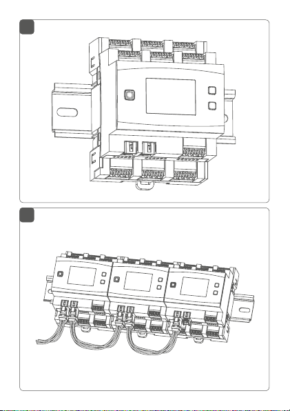
• Setzen Sie das Eingangsmodul auf die Hutschiene
auf (s. Abbildung 3). Achten Sie darauf, dass die
Schrift auf dem Gerät und im Display für Sie lesbar
ist und die Anschlussklemmen der Ka näle 1 bis 8
und 17 bis 28 oben liegen.
• Achten Sie bei der Montage darauf, dass die Rastfeder komplett einrastet und das Gerät fest auf
der Schiene sitzt.
• Verdrahten Sie das Gerät gemäß der Anschlusszeichnung in Abbildung 2.
• Verbinden Sie den Bus mit dem beiliegendem
Verbindungskabel (s. Abbildung 4).
• Setzen Sie den mitgelieferten Bus-Blindstopfen
ein, wenn Busanschluss 1 (E) oder Busanschluss
2 (F) nicht benötigt werden.
• Setzen Sie die Abdeckung des Stromkreisverteilers wieder auf.
• Schalten Sie die Haussicherung wieder ein, um
den Anlernmodus des Geräts zu aktivieren (s. „5.4
Anlernen“ auf Seite 20).
Nach der Installation und vor dem Anlernen des Geräts an die App, stehen Ihnen bereits einfache Bedienfunktionen (ggf. für Testzwecke) direkt am Gerät zur Verfügung (s. „6 Bedienung“ auf Seite 25).
19
Page 20

Inbetriebnahme
5.4 Anlernen
Bitte lesen Sie diesen Abschnitt erst vollständig,
bevor Sie mit dem Anlernen beginnen.
Richten Sie zunächst Ihren Homematic IP Wired
Access Point ein, um weitere Homematic IP Wired Geräte im System nutzen zu können. Ausführliche Informationen dazu finden Sie in der
Bedienungsanleitung des Wired Access Points.
Damit das Eingangsmodul in Ihr System integriert
werden und mit anderen Homematic IP Wired Geräten
kommunizieren kann, muss es zunächst angelernt
werden.
Sie haben die Möglichkeit, das Eingangsmodul für
eine lokale Konfiguration per PC an die Zentrale CCU3
anzulernen.
Alternativ können Sie das Gerät für eine flexible Steuerung
per Smartphone-App an die Homematic IP Cloud anlernen. Dabei ist es möglich, das Wired System
• per Smartphone-App über den Homematic IP
Wired Access Point (HmIPW-DRAP) zu steuern
oder
• mit Homematic IP Funk-Komponenten über den
Homematic IP Access Point (HmIP-HAP) zu kombinieren.
20
Page 21

Inbetriebnahme
5.4.1 Anlernen an die Zentrale CCU3
Nach dem Einbinden in die WebUI können Sie Ihr Homematic IP Wired Gerät softwarebasiert und komfortabel
steuern und konfigurieren sowie in Zentralenprogrammen nutzen. Um das Eingangsmodul an die Zentrale
CCU3 anzulernen, gehen Sie wie folgt vor:
• Richten Sie zunächst Ihre Zentrale CCU3 gemäß
der zugehörigen Bedienungsanleitung ein und
lernen Sie den Homematic IP Wired Access Point
an.
• Starten Sie die Benutzeroberfläche „Homematic
WebUI“ auf Ihrem PC.
• Klicken Sie auf den Button „Geräte anlernen“ im
rechten oberen Bereich des Browserfensters.
• Um den Anlernmodus zu aktivieren, klicken Sie
im nächsten Fenster auf „HmIP Gerät anlernen“.
Die Zentrale wird für 60 Sekunden in den Anlernmodus versetzt. Ein Infofeld zeigt die aktuell noch
verbleibende Anlernzeit.
21
Page 22

Inbetriebnahme
• Nach dem Anschluss an die Busleitung, ist der
Anlernmodus des Eingangsmoduls für 3 Minuten
aktiv. Sind die 3 Minuten noch nicht verstrichen,
wird das Gerät automatisch angelernt.
Sie können den Anlernmodus manuell für weitere
3 Minuten starten, indem Sie die Systemtaste (A)
kurz drücken (s. Abbildung 5).
• Warten Sie, bis der Anlernvorgang abgeschlossen
ist.
• Zur Bestätigung eines erfolgreichen Anlernvor-
22
Page 23

Inbetriebnahme
gangs leuchtet die LED (A) grün. Das Gerät ist nun
einsatzbereit.
• Leuchtet die LED rot, versuchen Sie es erneut.
• Nach kurzer Zeit erscheint das neu angelernte
Gerät im Posteingang Ihrer Softwareoberfläche.
Neu angelernte Geräte und die zugehörigen Kanäle stehen erst dann für Bedien- und Konfigurationsaufgaben
zur Verfügung, nachdem sie im Posteingang konfiguriert
wurden. Weitere Informationen finden Sie im HomematicIP Wired Systemhandbuch unter www.eQ-3.de.
Im Betrieb ohne aktiven Internetzugang wählen
Sie die Option „Homematic IP Gerät ohne Inter-
netzugang anlernen“. Geben Sie zum Anlernen
die SGTIN und den Key des Geräts in die entsprechenden Felder ein. Die SGTIN und den Key finden Sie auf dem beiliegenden Sticker. Bitte bewahren Sie den Sticker sorgfältig auf.
5.4.2 Anlernen an die Homematic IP Cloud per Wired
Access Point
Wenn Sie Ihre Homematic IP Wired Geräte flexibel per
Smartphone-App steuern möchten, können Sie die
Homematic IP Wired Geräte einfach an die HomematicIP
Cloud anlernen. Gehen Sie dazu wie folgt vor:
• Önen Sie die Homematic IP App auf Ihrem
23
Page 24

Inbetriebnahme
Smartphone.
• Lernen Sie den Homematic IP Wired Access Point
gemäß der zugehörigen Bedienungsanleitung
über die Smartphone-App an die Homematic IP
Cloud an.
• Wählen Sie den Menüpunkt „Gerät anlernen“ aus.
• Nach dem Anschluss an die Busleitung, ist der Anlernmodus des Eingangsmoduls für 3 Minuten aktiv.
Sie können den Anlernmodus manuell für weitere
3 Minuten starten, indem Sie die Systemtaste (A)
kurz drücken (s. Abbildung 5).
• Das Gerät erscheint automatisch in der Homematic IP App.
• Zur Bestätigung geben Sie in der App die letzten
vier Ziern der Gerätenummer (SGTIN) ein oder
scannen Sie den QR-Code. Die Gerätenummer
finden Sie auf dem Aufkleber im Lieferumfang
oder direkt am Gerät.
• Warten Sie, bis der Anlernvorgang abgeschlossen
ist.
• Zur Bestätigung eines erfolgreichen Anlernvorgangs leuchtet die LED (A) grün. Das Gerät ist nun
einsatzbereit.
• Leuchtet die LED rot, versuchen Sie es erneut.
• Wählen Sie die gewünschte Lösung für Ihr Gerät
aus.
24
Page 25

Bedienung
• Vergeben Sie in der App einen Namen für das Gerät und ordnen Sie es einem Raum zu.
Wenn Sie bereits Homematic IP Geräte im SmartHome-System nutzen oder Ihre Wired Geräte mit
Funk-Komponenten von Homematic IP kombinieren möchten, können Sie die Homematic IP
Wired Geräte auch einfach an einen (bestehen
den) Homematic IP Access Point anlernen. Lernen
Sie dazu den Homematic IP Wired Access Point
gemäß der zugehörigen Bedienungsanleitung an
den (bestehenden) Homematic IP Access Point
an. Anschließend gehen Sie wie oben beschrieben
vor, um das Eingangsmodul anzulernen.
6 Bedienung
Über die folgenden Tasten stehen Ihnen einfache Bedienfunktionen direkt am Gerät zur Verfügung:
• Systemtaste (A)
• Channel-Taste (B)
• Select-Taste (C)
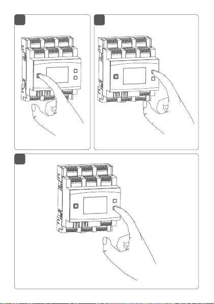
Systemtaste
Durch kurzes Drücken der Systemtaste (s. Abbildung 5)
können Sie die LCD-Hintergrundbeleuchtung bei allen an
den Bus angeschlossenen Geräten aktivieren.
-
25
Page 26

Bedienung
Channel-Taste
Durch kurzes Drücken der Channel-Taste (s. Abbildung 6)
können Sie den gewünschten Kanal auswählen. Bei jeder
Betätigung wird ein Kanal weitergeschaltet.
Der ausgewählte Kanal wird durch Blinken des Symbols
gekennzeichnet.
Select-Taste
Wenn Sie über die Channel-Taste einen Kanal ausgewählt
haben (s. Channel-Taste), können Sie durch kurzes Drücken der Select-Taste (s. Abbildung 7) einen Tastendruck
des an den ausgewählten Eingang angeschlossenen Tasters simulieren und die verknüpften Aktoren schalten.
Wenn Sie zuvor keinen Kanal ausgewählt haben, können
Sie durch kurzes Drücken der Select-Taste die folgenden
Anzeigen im LC-Display auswählen:
• Bus-Versorgungsspannung (in V)
• Temperatur im Gerät (in °C)
• Leere Anzeige
26
Page 27

Fehlercodes und Blinkfolgen
7 Fehlercodes und Blinkfolgen
Blinkcode/
LCD-Anzeige
Kurzes
oranges
Blinken
(alle 10 s)
6x langes
rotes Blinken
1x oranges
und 1x
grünes
Leuchten
E10 Temperatur
Bedeutung Lösung
Anlernmodus
aktiv
Gerät defekt Achten Sie auf die
Testanzeige Nachdem die
zu hoch
Geben Sie die letzten
vier Ziern der GeräteSeriennummer zur
Bestätigung ein (s. „5.4
Anlernen“ auf Seite
20).
Anzeige in Ihrer App
oder wenden Sie sich
an Ihren Fachhändler.
Testanzeige erloschen
ist, können Sie
fortfahren.
Reduzieren Sie die
angeschlossene Last
und lassen Sie das Gerät
abkühlen.
27
Page 28

Wiederherstellung der Werkseinstellungen
E11 Unterspan-
nung (Busspannung zu
niedrig)
Kontrollieren Sie die
Spannungsversorgung
und dimensionieren
Sie die Spannungsversorgung passend zur
Anzahl angeschlossener
Geräte.
8 Wiederherstellung der
Werkseinstellungen
Die Werkseinstellungen des Geräts können wiederhergestellt werden. Dabei gehen alle Einstellungen verloren.
Um die Werkseinstellungen des Eingangsmoduls wiederherzustellen, gehen Sie wie folgt vor:
• Drücken Sie für 4 s auf die Systemtaste (A), bis
die LED (A) schnell orange zu blinken beginnt (s.
Abbildung 5).
• Lassen Sie die Systemtaste wieder los.
• Drücken Sie die Systemtaste erneut für 4 s, bis die
LED grün aufleuchtet.
• Lassen Sie die Systemtaste wieder los, um das
Wiederherstellen der Werkseinstellungen abzuschließen.
Das Gerät führt einen Neustart durch.
28
Page 29

Wartung und Reinigung
9 Wartung und Reinigung
Das Gerät ist wartungsfrei. Überlassen Sie eine Wartung oder Reparatur einer Fachkraft.
Schalten Sie vor Ausbau des Geräts unbedingt die
Netzspannung frei (Sicherungsautomat abschalten)! Arbeiten am 230 V-Netz dürfen nur von einer Elektro-Fachkraft (nach VDE 0100) erfolgen.
Reinigen Sie das Gerät mit einem weichen, sauberen, trockenen und fusselfreien Tuch. Verwenden Sie keine lösemittelhaltigen Reinigungsmittel, das Kunststogehäuse
und die Beschriftung können dadurch angegrien werden.
10 Technische Daten
Geräte-Kurzbezeichnung:
Versorgungsspannung: 24 VDC, ±5 %, SELV
Stromaufnahme: 135 mA max./2,5 mA typ.
Leistungsaufnahme Ruhebetrieb:
Eingänge
Anzahl: 32
Signalspannung: 24 V
„0“-Signal: 0 bis 14 V
„1“-Signal: 18 bis 24 VDC
Signalstrom: 3,2 mA (Korrosionsschutz:
Signaldauer: min. 80 ms
HmIPW-DRI32
60 mW
DC, SELV
DC
ca. 125 mA)
29
Page 30

Technische Daten
max. Leitungslänge: 200 m
Verlustleistung des Geräts
für Wärmeberechnung: max. 3,25 W
Leitungsart und -querschnitt: starre und flexible Leitung,
0,25-1,5 mm²
Installation: auf Tragschiene (Hut-
schiene, DIN-Rail) gemäß
EN60715
Schutzart: IP20
Umgebungstemperatur: -5 bis +40 °C
Abmessungen (B x H x T): 72 x 90 x 69 mm (4 TE)
Gewicht: 165 g
Technische Änderungen vorbehalten.
Entsorgungshinweis
Gerät nicht im Hausmüll entsorgen! Elektronische Geräte sind entsprechend der Richtlinie
über Elektro- und Elektronik-Altgeräte über die
örtlichen Sammelstellen für Elektronik-Altgeräte
zu entsorgen.
Konformitätshinweis
Das CE-Zeichen ist ein Freiverkehrszeichen, das
sich ausschließlich an die Behörden wendet und
keine Zusicherung von Eigenschaften beinhaltet.
Bei technischen Fragen zum Gerät wenden Sie
sich bitte an Ihren Fachhändler.
30
Page 31

Package contents
Quantity Description
1 Homematic IP Wired Input Module –
32 channels
1 Bus connection cable
1 Bus blind plug
1 Operating manual
Documentation © 2018 eQ-3 AG, Germany.
All rights reserved. Translation from the original version in German. This manual may not be reproduced in any format, either in
whole or in part, nor may it be duplicated or edited by electronic,
mechanical or chemical means, without the written consent of
the publisher.
Typographical and printing errors cannot be excluded. However,
the information contained in this manual is reviewed on a regular
basis and any necessary corrections will be implemented in the
next edition. We accept no liability for technical or typographical
errors or the consequences thereof.
All trademarks and industrial property rights are acknowledged.
Printed in Hong Kong
Changes may be made without prior notice as a result of technical advances.
151693 (web)
Version 2.0 (06/2018)
31
Page 32

Table of contents
1 Information about this manual....................................33
2 Hazard information ........................................................33
3 Function and device overview ....................................36
4 General system information ........................................38
5 Start-up ............................................................................39
5.1 Installation instructions ..................................................... 39
5.2 Selecting the supply voltage .............................................41
5.3 Mounting and installation ................................................. 42
5.4 Teaching-in ..........................................................................44
5.4.1 Connecting to the Homematic IP Central
Control Unit CCU3 ................................................ 45
5.4.2 Connecting to the Homematic IP cloud via
6 Operation ........................................................................ 49
7 Error codes and flashing sequences .......................... 51
8 Restore factory settings ................................................52
9 Maintenance and cleaning ........................................... 52
10 Technical specifications ................................................53
32
Wired Access Point .................................................47
Page 33

Information about this manual
1 Information about this manual
Please read this manual carefully before beginning operation with your Homematic IP Wired component. Keep
the manual so you can refer to it at a later date if you
need to.
If you hand over the device to other persons for use,
please hand over this manual as well.
Symbols used:
Attention!
This indicates a hazard.
Please note: This section contains important additional information.
2 Hazard information
Do not open the device. It does not contain any
parts that can be maintained by the user. There is
a risk of electric shock if the device is opened. If
you have any doubts, have the device checked by
an expert.
For safety and licensing reasons (CE), unauthorized change and/or modification of the device is
not permitted.
33
Page 34

Hazard information
Do not use the device if there are signs of damage to the housing, control elements or connecting sockets, for example. If you have any doubts,
have the device checked by an expert.
The device may only be operated in dry and dustfree environment and must be protected from
the eects of moisture, vibrations, solar or other
methods of heat radiation, cold and mechanical
loads.
The device is not a toy; do not allow children to
play with it. Do not leave packaging material lying
around. Plastic films/bags, pieces of polystyrene,
etc. can be dangerous in the hands of a child.
We do not assume any liability for damage to
property or personal injury caused by improper
use or the failure to observe the hazard information. In such cases, any claim under warranty is
extinguished! For consequential damages, we assume no liability!
The input module is part of the building installation. The relevant national standards and directives must be taken into consideration during
planning and set-up. The input module is intended for operation within the Homematic IP Wired
34
Page 35

Hazard information
bus only. The Homematic IP Wired bus is a SELV
power circuit. The power supply of the building
installation and the Homematic IP Wired bus have
to be laid separately. Common cable routing for
power supply and the Homematic IP Wired bus in
installation and junction boxes is not permitted.
The required isolation for power supply of the
building installation to the Homematic IP Wired
bus must be observed at all times. Non-compliance with the installation instructions can cause
fire or introduce other hazards.
For secure operation, the device has to be installed
in a power distribution panel according to VDE
0603, DIN 43871 (low-voltage sub-distribution
board), DIN 18015-x. The installation must be car
ried out on a mounting rail (DIN rail) according to
EN 60715. Installation and wiring have to be per
formed according to VDE 0100 (VDE 0100-410,
VDE 0100-510 etc.). Please consider the technical
connection requirements (TAB) of your energy
supplier.
When connecting to the device terminals, take
the permissible cables and cable cross sections
into account.
35
Page 36

Function and device overview
Before installation and connection of the device,
mains voltage must be disconnected and live
parts in the surrounding must be covered.
The device may only be operated within domestic environment, in business and trade areas as
well as in small enterprises.
If you use the device/system in a security application it has to be operated in connection with an
UPS (uninterruptible power supply) in order to
bridge possible power failure.
Using the device for any purpose other than that
described in this operating manual does not fall
within the scope of intended use and shall invalidate any warranty or liability.
3 Function and device overview
The Homematic IP Wired Input Module – 32 channels
can be easily installed on a DIN rail within a distribution
board. The 32 inputs can be used to connect several
switches and push-buttons. Thus, it is possible to switch
and dim lamps or other lighting systems via connected
Homematic IP Wired switching or dimming actuators.
36
Page 37

Function and device overview
You can also configure single inputs of the module as
sensor inputs, in order to monitor e.g. normally closed or
normally open contacts.
The input module oers a special function for the
use of mains voltage push-buttons or switches. In
order to prevent corrosion and possible functional
limitations of the push-button or switch, for each
input a “Corrosion protection” can be activated.
This ensures that temporarily increased current is
flowing trough the push-button or switch when it
is actuated. The current pulse prevents from cor
rosion. The function is deactivated in the default
settings and can be separately switched on for
each channel.
Device overview (see figure 1):
(A) System button (teach-in/pairing button and LED)
(B) Channel button
(C) Select button
(D) LC display
Bus connection 1
(E)
(F) Bus connection 2
(G) Input terminals
(H) Ground terminals (GND)
37
-
Page 38

General system information
EDF
°C
B
C
G
G
H
H
EDF
°C
B
C
G
G
H
H
RX
1 1
RX
TX
1 1
V
Display overview (see figure 1):
Symbol Meaning
4 General system information
This device is part of the Homematic IP smart home
system and works with the Homematic IP protocol. All
devices of the system can be configured comfortably
and individually with the user interface of the Central
Control Unit CCU3 or flexibly via the Homematic IP
smartphone app in connection with the Homematic IP
cloud. All available functions provided by the system in
combination with other components are described in
the Homematic IP Wired Installation Guide. All current
technical documents and updates are provided at
www.eQ-3.com.
38
Input not activated
Input activated
Data is received by the bus
Data is sent to the bus
Temperature indication (switched on, if
temperature is displayed)
Voltage indication (switched on, if voltage
is displayed)
Page 39

5 Start-up
5.1 Installation instructions
Please observe the hazard information in section
„2 Hazard information“ on page 28 during in
stallation.
Please note the insulation stripping length of the
conductor to be connected, indicated on the
device.
The inputs are not disconnected from the mains
voltage but provide the bus voltage. Connected
push-buttons, switches or other switching elements must be specified for a rated voltage of at
least 26 V.
For electrical safety reasons, only the supplied
Homematic IP Wired Bus Cable may be used for
connecting the device to the Homematic IP
Wired bus. Furthermore, an eQ-3 Homematic IP
Wired Bus Cable with other lengths (available as
accessory) can be used.
Rigid cables can be plugged directly into the
clamp terminal (push-in technology). To connect
flexible cables or to loosen any kind of conduc
tors, the white actuation lever at the top of the
clamp has to be pressed.
Start-up
-
-
39
Page 40

Start-up
The push-buttons provided in the connection
drawing can be replaced by switches or NC/NO
contacts.
The bus connections (E) and (F) are switched in
parallel. However, the incoming or outgoing bus
cable can be connected to any of the two connections.
Please note! Only to be installed by persons with
the relevant electro-technical knowledge and
experience!*
Incorrect installation can put
• your own life at risk;
• and the lives of other users of the electrical system.
Incorrect installation also means that you are running the
risk of serious damage to property, e.g. because of a fire.
You may be personally liable in the event of injuries or
damage to property.
Contact an electrical installer!
40
Page 41

Start-up
*Specialist knowledge required for installation:
The following specialist knowledge is particularly important during
installation:
• The “5 safety rules” to be used:
Disconnect from mains; Safeguard from switching on
again; Check that system is de-energised; Earth and
short circuit; Cover or cordon o neighbouring live parts;
• Select suitable tool, measuring equipment and, if necessary, personal safety equipment;
• Evaluation of measuring results;
• Selection of electrical installation material for safeguarding shut-o conditions;
• IP protection types;
• Installation of electrical installation material;
• Type of supply network (TN system, IT system, TT system) and the resulting connecting conditions (classical
zero balancing, protective earthing, required additional
measures etc.).
Permitted cable cross sections for connecting to the input module are:
rigid cable [mm2] flexible cable
without ferrule [mm2]
0.25.-1.50 0.25.-1.50
5.2 Selecting the supply voltage
Voltage supply for the input module is established only via
the Homematic IP Wired bus. The bus is supplied by the
Homematic IP Wired Access Point (HmIPW-DRAP) (please
refer to the user manual of the HmIPW-DRAP).
41
Page 42

Start-up
The maximum total current consumption is calculated
from the actual number of inputs used. Approximately
4 mA flow trough each operated input, when using all
inputs in sensor mode with NC contacts the results are
as follows:
I
= 2.5 mA + 32 * 4 mA = 130.5 mA
ges
In normal applications with mixed operation of push-buttons, switches and signalling contacts (16 push-buttons
and 8 NC contacts and 8 switches), an average power
consumption can be expected. The push-buttons only
influence the current consumption if they are operated
and are therefore negligible. Since only closed switches
must be taken into account, it is possible to use an average value here (half is the switches are closed). The NC
contacts are permanently closed and must there be taken
into account entirely. This results in an exemplary overall
current consumption of:
I
= 2.5 mA + (4 * 4 mA) + (8 * 4 mA) = 50.5 mA
ges
5.3 Mounting and installation
Please read this entire section before starting to
install the device.
Before installing and setting up the device, you
have to put a Homematic IP Wired Access Point
(HmIPW-DRAP) into operation first.
42
Page 43

Start-up
Before installation, please note the device number (SGTIN) labelled on the device as well as the
exact application purpose in order to make later
allocation easier. You can also find the device
number on the QR code sticker supplied.
To install the input module on a DIN rail within a distribution board, please proceed as follows:
• Disconnect the power distribution panel and
cover any live parts, if required (see hazard
information).
• Remove the cover of the power distribution panel.
• Place the input module onto the DIN rail (see
fig. 3). Make sure that you can read the letters on
the device and display and that the connecting
terminals of channel 1 to 8 and 17 to 28 are at
the top.
• During installation, make sure that the locating
springs engage properly and that the device is
securely seated on the rail.
• Wire the device according to the connecting
diagram in figure 2.
• Connect the bus using the supplied connecting
cable (see figure 4).
• Use the supplied bus blind plug, if bus connection
1 (E) or bus connection 2 (F) are not needed.
• Reattach the cover of the power distribution panel.
• Switch the fuse of the power circuit on again to
43
Page 44

Start-up
activate the teach-in mode of the device (see „5.4
Teaching-in“ on page 44).
After installation and before connecting the device
to the app, simple operating functions (e.g. for test
purposes) are available directly on the device („6
Operation“ on page 49).
5.4 Teaching-in
Please read this entire section before starting
the teach-in procedure.
First, set up your Homematic IP Wired Access
Point to enable operation of other Homematic IP
Wired devices within your system. For further information, please refer to the operating manual
of the Wired Access Point.
To integrate the input module into your system and
enable it to communicate with other Homematic IP
Wired devices, you must teach it in first.
You can connect the input module to the Central Control
Unit CCU3 for local configuration via PC.
As an alternative, connect the device to the HomematicIP
cloud for flexible control via smartphone app. You can
• control the wired system via smartphone app
using the Homematic IP Wired Access Point
(HmIPW-DRAP) or
44
Page 45

Start-up
• combine wired devices with wireless
Homematic P devices via the Homematic IP
Access Point (HmIP-HAP).
5.4.1 Connecting to the Homematic IP Central
Control Unit CCU3
After connecting the Homematic IP Wired device to the
WebUI it can be conveniently controlled, configured and
be used in central control unit programs via the software
interface. To connect the input module to the Central
Control Unit CCU3, proceed as follows:
• Set up your Central Control Unit CCU3 as described in the operating manual and connect the
Homematic IP Wired Access Point.
• Start the user interface “Homematic WebUI” on
your computer.
• Click the “Teach-in devices” button on the righthand side of the screen.
• To activate teach-in mode, click “Teach-in HmIP
device” in the next window. The teach-in mode
45
Page 46

Start-up
of the Central Control Unit will be activated for
60 seconds. An information box shows how
much teach-in time remains.
• After connecting to the bus line, the teach-in
mode of the input module remains activated for
3 minutes. If the 3 minutes have not yet expired,
the device will be connected automatically.
You can manually start the teach-in mode for another 3 minutes by pressing the system button (A)
briefly (see figure 5).
• Please wait until teach-in is completed.
46
Page 47

Start-up
• If connecting was successful, the LED (A) lights
up green. The device is now ready for use.
• If the LED lights up red, please try again.
• After a short time, the newly connected device
appears in the inbox of your software interface.
Newly connected devices and the corresponding channels are ready for operation and configuration only after
they have been configured in the inbox. You will find further information in the Homematic IP Wired Installation
Guide, available for download at www.eQ-3.com.
For operation without Internet connection, please
select the option “Teaching-in of Homematic IP
device without Internet connection”. Please enter the SGTIN and key of the device into the corresponding fields. You will find the SGTIN and the
key on the supplied sticker. Please keep the sticker
in safe place.
5.4.2 Connecting to the Homematic IP cloud via
Wired Access Point
If you want to control your Homematic IP Wired devices
flexibly via smartphone app, they can be connected to
the Homematic IP cloud. To do this, please proceed as
follows:
• Open the Homematic IP app on your smart-
47
Page 48

Start-up
phone.
• Connect the Homematic IP Wired Access Point
via the smartphone app to the Homematic IP
cloud, as described in the corresponding user
manual
• Select the menu item “Teach-in device”.
• After connecting to the bus line, the teach-in
mode of the input module remains activated for
3 minutes.
You can manually start the teach-in mode for another 3 minutes by pressing the system button (A)
briefly (see figure 5).
• Your device will automatically appear in the
Homematic IP app.
• To confirm, please enter the last four digits of the
device number (SGTIN) in your app or scan the
QR code. Therefore, please see the sticker supplied or attached to the device.
• Please wait until teach-in is completed.
• If connecting was successful, the LED (A) lights
up green. The device is now ready for use.
• If the LED lights up red, please try again.
• Select the desired solution for your device.
• In the app, give the device a name and allocate
it to a room.
48
Page 49

Operation
If you are already using Homematic IP devices in
your smart home system or if you want to
combine your Homematic IP Wired devices with
wireless Homematic IP components, you can also
connect the Homematic IP Wired devices to an
(installed) Access Point. Therefore, connect the
Homematic IP Wired Access Point to the (already
installed) Homematic IP Access Point, as
described in the user manual. Afterwards, please
proceed as described above to connect the input
module.
6 Operation
Via the following push-buttons, simple operating functions are available directly on the device:
• System button (A)
• Channel button (B)
• Select button (C)
System button
By pressing the system button briefly (see figure 5), you
can activate the LCD background lighting of all devices
connected to the bus.
Channel button
By pressing the channel button briefly (see figure 6) you
can select the desired channel. On each button press,
49
Page 50

Operation
you can switch to the next channel.
The selected channel is indicated by the flashing symbol.
Select button
After selecting a channel via the channel button (see
‘Channel button’), you can simulate a button-press of the
selected input at the connected push-button and switch
connected actuators by briefly pressing the select button
(see figure 7).
If you have not selected a channel previously, you can
select the following options in the LC display by pressing
the Select button briefly:
• Bus supply voltage (in V)
• Temperature in the device (in °C)
• Empty display
50
Page 51

Error codes and flashing sequences
7 Error codes and flashing
sequences
Flashing
code / LC
display
Short
orange
flashing
(every 10 s)
6x long
red flashing
1x orange
and 1x
green lighting
E10 Temperature
E11 Under-
Meaning Solution
Teach-in
mode active
Device
defective
Test display Once the test display
too high
voltage (bus
voltage too
low)
Please enter the last
four numbers of the
device serial number
to confirm (see „5.4
Teaching-in“ on page
44).
Please see your app
for error message or
contact your retailer.
has stopped, you can
continue.
Reduce the connected
load and let the device
cool down.
Check the voltage
supply and adjust
the voltage supply in
accordance with the
number of devices connected.
51
Page 52

Restore factory settings
8 Restore factory settings
The factory settings of the device can be restored. If you do this, you will lose all your settings.
To restore the factory settings of the input module, please
proceed as follows:
• Press and hold down the system button (A) for 4
seconds until the LED (A) quickly starts flashing
orange (see figure 5).
• Release the system button again.
• Press and hold down the system button again for
4 seconds, until the LED lights up green.
• Release the system button to finish the procedure.
The device will perform a restart.
9 Maintenance and cleaning
The product does not require any maintenance.
Enlist the help of an expert to carry out any main
tenance or repairs.
The mains voltage must be disconnected before
the device is removed (trip the miniature circuitbreaker). Only qualified electricians (to VDE 0100)
are permitted to carry out work on the 230 V
mains.
52
-
Page 53

Technical specifications
Clean the device using a soft, lint-free cloth that is clean
and dry. Do not use any detergents containing solvents,
as they could corrode the plastic housing and label.
10 Technical specifications
Device short name:
Supply voltage: 24 VDC, +5 %, SELV
Current consumption: 135 mA max./2.5 mA
(typically)
Power consumption
in standby: 60 mW
Input
Quantity: 32
Signal voltage: 24 V
“0” signal: 0 to 14 VDC
“1” signal: 18 to 24 VDC
Signal current: 3.2 mA (corrosion
Signal duration: at least 80 ms
Max. line length: 200 m
Power loss of the device
for thermal calculation: 3.25 W max.
Cable type and cross section:
Installation: mounting rail (DIN rail)
HmIPW-DRI32
DC, SELV
protection: approximately
125mA)
rigid and flexible cable,
0.25-1.5 mm²
according to EN 60715
53
Page 54

Technical specifications
Degree of protection: IP20
Ambient temperature: -5 to +40 °C
Dimensions (W x H x D): 72 x 90 x 69 mm (4 WM
width)
Weight: 165 g
Subject to technical changes.
Instructions for disposal
Do not dispose of the device with regular domestic waste! Electronic equipment must be disposed of at local collection points for waste electronic equipment in compliance with the Waste
Electrical and Electronic Equipment Directive.
Information about conformity
The CE sign is a free trading sign addressed exclusively to the authorities and does not include
any warranty of any properties.
For technical support, please contact your retailer.
54
Page 55

Kostenloser Download der Homematic IP App!
Free download of the Homematic IP app!
Bevollmächtigter des Herstellers:
Manufacturer’s authorised representative:
eQ-3 AG
Maiburger Straße 29
26789 Leer / GERMANY
www.eQ-3.de
 Loading...