

Page 1
Montage- und
Bedienungsanleitung
Mounting instruction and
User manual
Fenster- und Türkontakt –
optisch, plus
Window / Door Contact –
optical, plus
HmIP-SWDO-PL
S. 2
p. 28
Page 2

Lieferumfang
Anzahl Bezeichnung
1 Homematic IP Fenster- und Türkontakt –
2 Doppelseitige Klebestreifen
2 Schrauben 2,2 x 13 mm
1 Reflektoraufkleber (für dunkle Untergründe)
2 1,5 V LR03/Micro/AAA Batterien
1 Bedienungsanleitung
1 Beiblatt mit Sicherheitshinweisen
Dokumentation © 2019 eQ-3 AG, Deutschland
Alle Rechte vorbehalten. Ohne schriftliche Zustimmung des
Herausgebers darf diese Anleitung auch nicht auszugsweise in
irgendeiner Form reproduziert werden oder unter Verwendung
elektronischer, mechanischer oder chemischer Verfahren vervielfältigt oder verarbeitet werden.
Es ist möglich, dass die vorliegende Anleitung noch drucktechnische Mängel oder Druckfehler aufweist. Die Angaben in dieser
Anleitung werden jedoch regelmäßig überprüft und Korrekturen
in der nächsten Ausgabe vorgenommen. Für Fehler technischer
oder drucktechnischer Art und ihre Folgen übernehmen wir keine
Haftung.
Alle Warenzeichen und Schutzrechte werden anerkannt.
Printed in Hong Kong
Änderungen im Sinne des technischen Fortschritts können ohne
Vorankündigung vorgenommen werden.
154447 (web)
Version 1.0 (08/2019)
optisch, plus
Page 3
1
A
B
C
D
E
F
Page 4
2
1
2
3
Page 5
4
3 mm
3 mm
5
1
2
3
Page 6
6
1
2
70 mm
7
Page 7
8
9
4 s
Page 8
10
4 s
Page 9

Inhaltsverzeichnis
1 Hinweise zur Anleitung .................................................10
2 Gefahrenhinweise ..........................................................10
3 Funktion und Geräteübersicht ....................................12
4 Allgemeine Systeminformationen ..............................13
5 Inbetriebnahme .............................................................. 14
5.1 Anlernen ................................................................................14
5.2 Montage.................................................................................16
5.2.1 Auswahl eines geeigneten Montageortes .........16
5.2.2 Klebestreifen- oder Schraubmontage ................17
6 Batterien wechseln ........................................................19
7 Fehlerbehebung ............................................................ 20
7.1 Schwache Batterien ........................................................... 20
7.2 Befehl nicht bestätigt .......................................................... 21
7.3 Duty Cycle ............................................................................ 21
7.4 Fehlercodes und Blinkfolgen ........................................... 22
8 Wiederherstellung der Werkseinstellungen ..............24
9 Wartung und Reinigung ................................................25
10 Allgemeine Hinweise zum Funkbetrieb .....................25
11 Technische Daten ..........................................................26
9
Page 10
Hinweise zur Anleitung
1 Hinweise zur Anleitung
Lesen Sie diese Anleitung sorgfältig, bevor Sie Ihre
Homematic IP Geräte in Betrieb nehmen. Bewahren Sie
die Anleitung zum späteren Nachschlagen auf! Wenn Sie
das Gerät anderen Personen zur Nutzung überlassen,
übergeben Sie auch diese Anleitung.
Benutzte Symbole:
Achtung!
Hier wird auf eine Gefahr hingewiesen.
Hinweis.
Dieser Abschnitt enthält zusätzliche wichtige Informationen!
2 Gefahrenhinweise
Önen Sie das Gerät nicht. Es enthält keine durch
den Anwender zu wartenden Teile. Im Fehlerfall
lassen Sie das Gerät von einer Fachkraft prüfen.
Bei Sach- oder Personenschäden, die durch unsachgemäße Handhabung oder Nichtbeachten
der Gefahrenhinweise verursacht werden, übernehmen wir keine Haftung. In solchen Fällen erlischt jeder Gewährleistungsanspruch! Für Folgeschäden übernehmen wir keine Haftung!
10
Page 11
Gefahrenhinweise
Verwenden Sie das Gerät nicht, wenn es von außen erkennbare Schäden (z. B. am Gehäuse oder
an Bedienelementen) bzw. eine Funktionsstörung
aufweist. Das Gerät im Zweifelsfall von einer
Fachkraft prüfen lassen.
Aus Sicherheits- und Zulassungsgründen (CE) ist
das eigenmächtige Umbauen und/oder Verändern des Geräts nicht gestattet.
Betreiben Sie das Gerät nur in Innenräumen und
setzen Sie es keinem Einfluss von Feuchtigkeit,
Vibrationen, ständiger Sonnen- oder anderer
Wärmeeinstrahlung, übermäßiger Kälte und keinen mechanischen Belastungen aussetzen.
Das Gerät ist kein Spielzeug! Erlauben Sie Kindern
nicht damit zu spielen. Lassen Sie das Verpackungsmaterial nicht achtlos liegen. Plastikfolien/
-tüten, Styroporteile etc. können für Kinder zu
einem gefährlichen Spielzeug werden.
Dieses Gerät arbeitet mit unsichtbarem Infrarotlicht. Bitte halten Sie mindestens 20 cm Abstand
vom Gerät zum Auge ein!
11
Page 12

Funktion und Geräteübersicht
Das Gerät ist nur für den Einsatz im Umfeld von
Wohnbereichen, Geschäfts- und Gewerbebereichen sowie in Kleinbetrieben bestimmt.
Jeder andere Einsatz, als der in dieser Bedienungsanleitung beschriebene, ist nicht bestimmungsgemäß und führt zu Gewährleistungs- und
Haftungsausschluss.
3 Funktion und Geräteübersicht
Der Homematic IP Fenster- und Türkontakt erkennt zuverlässig das Önen bzw. Schließen von Fenstern oder Türen
ch einen integrierten Infrarot-Sensor.
dur
Geönete Fenster und Türen werden unmittelbar in der
Homematic IP App angezeigt – so können Sie auch von
unterwegs Ihre Fenster und Türen immer im Auge behalten.
Der Fenster- und Türkontakt bietet eine lange
Batterielebensdauer von bis zu 4 Jahren. Dank
Batteriebetrieb und Funkkommunikation kann das Gerät
flexibel montiert werden und ist durch das mitgelieferte
Montagematerial leicht am Fenster- oder Türrahmen zu
befestigen.
Durch den eingebauten Sabotagekontakt werden Sie bei
Manipulation des Fenster- und Türkontakts sofort über
die App informiert.
12
Page 13

Allgemeine Systeminformationen
Starkes Fremdlicht und Verschmutzungen des Sensors können zu Funktionseinschränkungen führen.
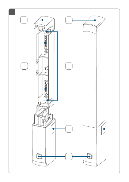
Geräteübersicht (s. Abbildung 1):
(A) Elektronikeinheit
(B) Abdeckkappe
(C) Batteriefach
(D) Schraublöcher
(E) Infrarot-Sensor
(F) Systemtaste (Anlerntaste und LED)
4 Allgemeine Systeminformationen
Dieses Gerät ist Teil des Homematic IP Smart-HomeSystems und kommuniziert über das Homematic IP
Funkprotokoll. Alle Geräte des Systems können
komfortabel und individuell per Smartphone über die
Homematic IP App konfiguriert werden. Alternativ
haben Sie die Möglichkeit, Homematic IP Geräte über
die Zentrale CCU2/CCU3 oder in Verbindung mit vielen
Partnerlösungen zu betreiben. Welcher Funktionsumfang
sich innerhalb des Systems im Zusammenspiel mit
weiteren Komponenten ergibt, entnehmen Sie bitte dem
Homematic IP Anwenderhandbuch. Alle technischen
Dokumente und Updates finden Sie stets aktuell unter
www.homematic-ip.com.
13
Page 14
Inbetriebnahme
5 Inbetriebnahme
5.1 Anlernen
Bitte lesen Sie diesen Abschnitt erst vollständig,
bevor Sie mit dem Anlernen beginnen.
Richten Sie zunächst Ihren Homematic IP Access
Point über die Homematic IP App ein, um weitere
Homematic IP Geräte im System nutzen zu
können. Weitere Informationen dazu finden Sie in
der Bedienungsanleitung des Access Points.
Sie können das Gerät an den Access Point oder
an die Zentrale CCU2/CCU3 anlernen. Weitere
Informationen dazu entnehmen Sie bitte dem
Homematic IP Anwenderhandbuch.
Damit das Gerät in Ihr System integriert werden und mit
anderen Homematic IP Geräten kommunizieren kann,
muss es zunächst an den Homematic IP Access Point
angelernt werden.
Zum Anlernen gehen Sie wie folgt vor:
• Önen Sie die Homematic IP App auf Ihrem
Smartphone.
• Wählen Sie den Menüpunkt „Gerät anlernen“ aus.
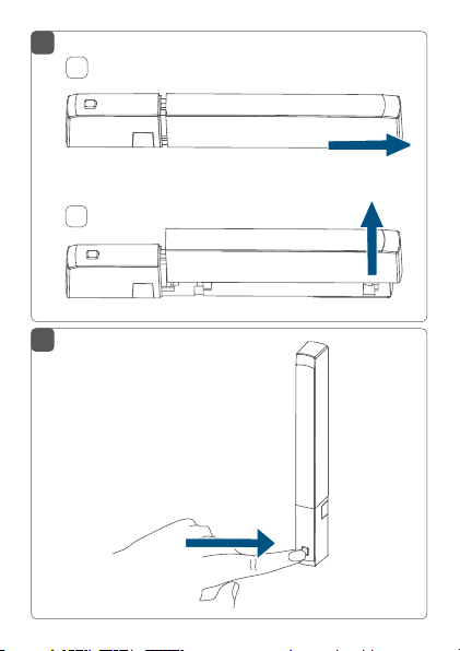
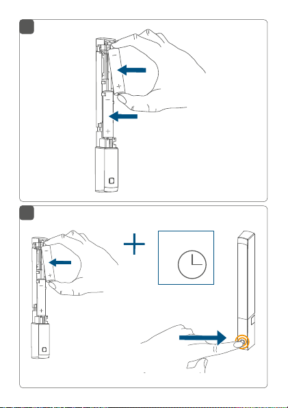
• Önen Sie das Batteriefach (C), indem Sie die
Abdeckkappe (B) erst ein kleines Stück nach
hinten und anschließend nach oben abziehen (s.
14
Page 15

Inbetriebnahme
Abbildung 2).
• Ziehen Sie den Isolierstreifen aus dem Batteriefach des Fenster- und Türkontakts heraus.
• Der Anlernmodus ist für 3 Minuten aktiv.
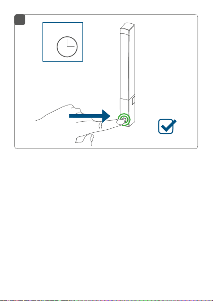
Sie können den Anlernmodus manuell für weitere
3 Minuten starten, indem Sie die Systemtaste (F)
kurz drücken (s. Abbildung 3).
• Das Gerät erscheint automatisch in der Homematic IP App.
• Zur Bestätigung geben Sie in der App die letzten
vier Ziern der Gerätenummer (SGTIN) ein oder
scannen Sie den QR-Code. Die Gerätenummer
finden Sie auf dem Aufkleber im Lieferumfang
oder direkt am Gerät.
• Warten Sie, bis der Anlernvorgang abgeschlossen
ist.
• Zur Bestätigung eines erfolgreichen Anlernvorgangs leuchtet die LED (F) grün. Das Gerät ist nun
einsatzbereit.
• Leuchtet die LED rot, versuchen Sie es erneut.
• Wählen Sie in der App aus, in welchen Lösungen
(z. B. Raumklima und/oder Sicherheit) das Gerät
eingesetzt werden soll.
• Ordnen Sie das Gerät in der App einem Raum zu
und vergeben Sie einen Namen für das Gerät.
• Setzen Sie die Abdeckkappe noch nicht auf.
15
Page 16

Inbetriebnahme
5.2 Montage
Bitte lesen Sie diesen Abschnitt erst vollständig,
bevor Sie mit der Montage beginnen.
5.2.1 Auswahl eines geeigneten Montageortes
• Wählen Sie das Fenster oder die Tür für die Montage des Fenster- und Türkontakts aus.
• Befestigen Sie den Fenster- und Türkontakt auf
der Seite des Fenster-/Türgries im oberen Drittel
auf dem Fenster-/Türrahmen (zur Befestigung s.
„5.2.2 Klebestreifen- oder Schraubmontage“ auf
Seite 17) (s. Abbildung 4).
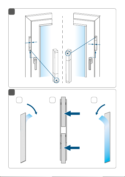
• Der Infrarot-Sensor (E) muss in Richtung des
Fenster-/Türflügels zeigen (s. Abbildung 4).
Der ideale Abstand zwischen der Gehäusekante
des Fenster- und Türkontakts und dem Tür-/
Fensterflügel beträgt 3 mm (s. Abbildung 4).
• Befindet sich der Fenster-/Türgri auf der rechten
Seite, müssen Sie den Fenster- und Türkontakt
drehen, damit der Infrarot-Sensor (E) auch auf dieser Seite in Richtung des Fenster-/Türflügels zeigt
(s. Abbildung 4).
Ist der Fenster-/Türrahmen für die Montage des
Fenster- und Türkontakts zu schmal, kann das
Gerät nicht montiert werden.
16
Page 17

Inbetriebnahme
Bei schlecht reflektierenden Untergründen (z. B.
dunklen Fensterrahmen) muss der mitgelieferte
Reflektoraufkleber an die Innenkante vom Fenster-/Türflügel gegenüber dem Infrarot-Sensor des
Fenster- und Türkontakts angebracht werden.
5.2.2 Klebestreifen- oder Schraubmontage
Sie können das Gerät
• mit den mitgelieferten doppelseitigen Klebestreifen oder
• mit den mitgelieferten Schrauben
am Fenster-/Türrahmen befestigen.
Klebestreifenmontage
Achten Sie darauf, dass der Montageuntergrund
glatt, eben, unbeschädigt, sauber, fett- sowie lösungsmittelfrei und nicht zu kühl ist, damit dieKlebestreifen langfristig haften können.
Um das Gerät mit den Klebestreifen zu montieren, gehen
Sie wie folgt vor:
• Setzen Sie die Abdeckkappe (B) auf die Elektronikeinheit (A) auf.
• Bringen Sie die doppelseitigen Klebestreifen auf
der Rückseite der Elektronikeinheit (A) an, entfernen Sie die Abziehfolie und drücken Sie das Gerät
an die gewünschte Position am Fenster-/Türrahmen (s. Abbildung 5).
17
Page 18

Inbetriebnahme
Für ein rückstandsloses und leichtes Entfernen
der Klebestreifen, lassen Sie die Klebestreifen etwas über den Gehäuserand überstehen.
Schraubmontage
Durch die Schraubmontage wird die Tür bzw. das
Fenster beschädigt. Bei Mietwohnungen könnte
dies zu einer Schadensersatzforderung oder zum
Einbehalt der Mietkaution führen.
Um das Gerät mithilfe der Schrauben zu montieren, gehen Sie wie folgt vor:
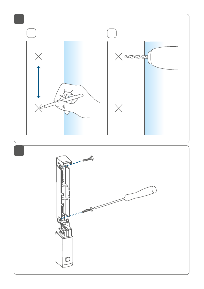
• Zeichnen Sie die Schraublöcher (D) bei
Befestigung des Geräts auf harten Untergründen
in einem Abstand von 70 mm an der gewünschten
Position auf dem Fenster-/Türrahmen an (s.
Abbildung 6).
• Bohren Sie bei Befestigung auf harten
Untergründen mit einem 1,5 mm Bohrer vor. Bei
weichen Untergründen ist dies nicht notwendig
(s. Abbildung 6).
Die Schraublöcher (D) müssen nicht vorgebohrt
werden. Sie können die Schrauben einfach durch
den Kunststo eindrehen.
• Halten Sie die Elektronikeinheit (A) an die gewünschte Montageposition und drehen Sie die
18
Page 19

Batterien wechseln
mitgelieferten Schrauben durch die Schraublöcher
in den Fenster-/Türrahmen ein (s. Abbildung 7).
• Setzen Sie die Abdeckkappe (B) auf die Elektronikeinheit auf.
6 Batterien wechseln
Wird eine leere Batterie in der App bzw. am Gerät angezeigt (s. „7.4 Fehlercodes und Blinkfolgen“ auf Seite 22),
tauschen Sie die verbrauchten Batterien gegen zwei neue
Batterien des Typs LR03/Micro/AAA aus. Beachten Sie dabei die richtige Polung der Batterien.
Um die Batterien zu wechseln, gehen Sie wie folgt vor:
• Önen Sie das Batteriefach (C), indem Sie die Abdeckkappe (B) erst ein kleines Stück nach hinten
und anschließend nach oben abziehen (s. Abbil-
dung 2).
• Entnehmen Sie die leeren Batterien.
• Legen Sie zwei neue 1,5 V LR03/Micro/AAA Batterien entsprechend der Polaritätsmarkierungen in
das Batteriefach ein (s. Abbildung 8).
• Achten Sie nach dem Einlegen der Batterien auf
die Blinkfolgen der LED (F) (s. „7.4 Fehlercodes
und Blinkfolgen“ auf Seite 22).
• Setzen Sie die Abdeckkappe wieder auf die Elektronikeinheit (A) auf.
19
Page 20

Fehlerbehebung
Nach dem Einlegen der Batterien führt das Gerät zunächst für ca. 2 Sekunden einen Selbsttest durch. Danach
erfolgt die Initialisierung. Den Abschluss bildet die TestAnzeige: oranges und grünes Leuchten.
Vorsicht! Explosionsgefahr bei unsachgemäßem
Austausch der Batterien. Ersatz nur durch denselben oder einen gleichwertigen Typ. Batterien
dürfen niemals aufgeladen werden. Batterien
nicht ins Feuer werfen. Batterien nicht übermäßiger Wärme aussetzen. Batterien nicht kurzschließen. Es besteht Explosionsgefahr!
Verbrauchte Batterien gehören nicht in den
Hausmüll! Entsorgen Sie diese in Ihrer örtlichen
Batteriesammelstelle!
7 Fehlerbehebung
7.1 Schwache Batterien
Wenn es der Spannungswert zulässt, ist das Gerät auch
bei niedriger Batteriespannung betriebsbereit. Je nach
Beanspruchung kann evtl. nach kurzer Erholungszeit der
Batterien wieder mehrfach gesendet werden.
Bricht beim Senden die Spannung wieder zusammen,
wird dies in der Homematic IP App und am Gerät angezeigt (s. „7.4 Fehlercodes und Blinkfolgen“ auf Seite
22). Tauschen Sie in diesem Fall die leeren Batterien
20
Page 21

Fehlerbehebung
gegen zwei neue aus (s. „6 Batterien wechseln“ auf Seite
19).
7.2 Befehl nicht bestätigt
Bestätigt mindestens ein Empfänger einen Befehl nicht, leuchtet zum Abschluss der fehlerhaften Übertragung die Geräte-LED (F) rot auf. Grund
für die fehlerhafte Übertragung kann eine Funkstörung sein (s. „10 Allgemeine Hinweise zum
Funkbetrieb“ auf Seite 25). Die fehlerhafte Übertragung kann folgende Ursachen haben:
• Empfänger nicht erreichbar,
• Empfänger kann Befehl nicht ausführen (Lastausfall, mechanische Blockade etc.) oder
• Empfänger defekt.
7.3 Duty Cycle
Der Duty Cycle beschreibt eine gesetzlich geregelte Begrenzung der Sendezeit von Geräten im 868 MHz Bereich. Das Ziel dieser Regelung ist es, die Funktion aller im
868 MHz Bereich arbeitenden Geräte zu gewährleisten.
In dem von uns genutzten Frequenzbereich 868 MHz beträgt die maximale Sendezeit eines jeden Geräts 1 % einer
Stunde (also 36 Sekunden in einer Stunde). Die Geräte
dürfen bei Erreichen des 1 %-Limits nicht mehr senden,
bis diese zeitliche Begrenzung vorüber ist. Gemäß dieser
Richtlinie, werden Homematic IP-Geräte zu 100 % normenkonform entwickelt und produziert.
21
Page 22

Fehlerbehebung
Im normalen Betrieb wird der Duty Cycle in der Regel
nicht erreicht. Dies kann jedoch in Einzelfällen bei der Inbetriebnahme oder Erstinstallation eines Systems durch
vermehrte und funkintensive Anlernprozesse der Fall sein.
Eine Überschreitung des Duty Cycle Limits wird durch
einmal langes rotes Blinken der Geräte-LED (F) angezeigt
und kann sich durch temporär fehlende Funktion des
Geräts äußern. Nach kurzer Zeit (max. 1 Stunde) ist die
Funktion des Geräts wiederhergestellt.
7.4 Fehlercodes und Blinkfolgen
Blinkcode Bedeutung Lösung
Kurzes oranges
Blinken
1x langes
grünes
Leuchten
1x langes rotes
Leuchten
22
Funkübertragung/
Sendeversuch/
Datenübertragung
Vorgang
bestätigt
Vorgang
fehlgeschlagen oder Duty
Cycle-Limit
erreicht
Warten Sie, bis
die Übertragung
beendet ist.
Sie können mit
der Bedienung
fortfahren.
Versuchen Sie
es erneut (s. „7.2
Befehl nicht bestätigt“ auf Seite 21
oder „7.3 Duty
Cycle“ auf Seite
21).
Page 23

Fehlerbehebung
Kurzes oranges
Blinken (alle
10 s)
Kurzes oranges
Leuchten (nach
grüner oder
roter Empfangsmeldung)
Langes und
kurzes oranges
Blinken (im
Wechsel)
6x langes rotes
Blinken
1x oranges
und 1x grünes
Leuchten (nach
dem Einlegen
der Batterie)
Anlernmodus
aktiv
Batterien leer Tauschen Sie die
Aktualisierung
der Gerätesoftware (OTAU)
Gerät defekt Achten Sie auf die
Testanzeige Nachdem die Test-
Geben Sie die
letzten vier Ziern
der GeräteSeriennummer zur
Bestätigung ein (s.
„5.1 Anlernen“ auf
Seite 14).
Batterien des Geräts aus (s. „6 Batterien wechseln“
auf Seite 19).
Warten Sie, bis das
Update beendet
ist.
Anzeige in Ihrer
App oder wenden
Sie sich an Ihren
Fachhändler.
anzeige erloschen
ist, können Sie
fortfahren.
23
Page 24

Wiederherstellung der Werkseinstellungen
8 Wiederherstellung der
Werkseinstellungen
Die Werkseinstellungen des Geräts können wiederhergestellt werden. Dabei gehen alle Einstellungen verloren.
Um die Werkseinstellungen des Geräts wiederherzustellen, gehen Sie wie folgt vor:
• Önen Sie das Batteriefach (C), indem Sie die Abdeckkappe (B) erst ein kleines Stück nach hinten
und anschließend nach oben abziehen (s. Abbil-
dung 2).
• Entnehmen Sie eine Batterie.
• Legen Sie die Batterie entsprechend der Polaritätsmarkierungen bei gleichzeitig gedrückter
Systemtaste (F) wieder ein. Halten Sie die Systemtaste solange gedrückt, bis die LED (F) schnell
orange zu blinken beginnt (s. Abbildung 9).
• Lassen Sie die Systemtaste kurz los und halten Sie
die Systemtaste dann erneut solange gedrückt,
bis das orange Blinken in ein grünes Leuchten
wechselt (s. Abbildung 10).
• Lassen Sie die Systemtaste wieder los, um das
Wiederherstellen der Werkseinstellungen abzuschließen.
Das Gerät führt einen Neustart durch.
24
Page 25

Wartung und Reinigung
9 Wartung und Reinigung
Das Gerät ist bis auf einen eventuell erforderlichen Batteriewechsel wartungsfrei. Überlassen
Sie eine Reparatur einer Fachkraft.
Reinigen Sie das Gerät mit einem weichen, sauberen,
trockenen und fusselfreien Tuch. Verwenden Sie keine
lösemittelhaltigen Reinigungsmittel, das Kunststogehäuse und die Beschriftung können dadurch angegrien
werden.
10 Allgemeine Hinweise zum
Funkbetrieb
Die Funk-Übertragung wird auf einem nicht exklusiven
Übertragungsweg realisiert, weshalb Störungen nicht
ausgeschlossen werden können. Weitere Störeinflüsse
können hervorgerufen werden durch Schaltvorgänge,
Elektromotoren oder defekte Elektrogeräte.
Die Reichweite in Gebäuden kann stark von der
im Freifeld abweichen. Außer der Sendeleistung
und den Empfangseigenschaften der Empfänger
spielen Umwelteinflüsse wie Luftfeuchtigkeit neben baulichen Gegebenheiten vor Ort eine wichtige Rolle.
25
Page 26

Technische Daten
Hiermit erklärt die eQ-3 AG, Maiburger Str. 29, 26789 Leer,
Deutschland, dass der Funkanlagentyp Homematic IP
HmIP-SWDO-PL der Richtlinie 2014/53/EU entspricht.
Der vollständige Text der EU-Konformitätserklärung
ist unter der folgenden Internetadresse verfügbar:
www.homematic-ip.com
11 Technische Daten
Geräte-Kurzbezeichnung:
Versorgungsspannung: 2x 1,5 V LR03/Micro/AAA
Stromaufnahme: 30 mA max.
Batterielebensdauer: 4 Jahre (typ.)
Schutzart: IP20
Umgebungstemperatur: -20 bis +55 °C
Abmessungen (B x H x T): 147 x 20 x 16 mm
Gewicht: 47 g (inkl. Batterien)
Funk-Frequenzband: 868,0-868,6 MHz
869,4-869,65 MHz
Maximale Funk-Sendeleistung: 10 dBm
Empfängerkategorie: SRD category 2
Typ. Funk-Freifeldreichweite: 220 m
Duty Cycle: < 1 % pro h/< 10 % pro h
Technische Änderungen vorbehalten.
26
HmIP-SWDO-PL
Page 27

Entsorgungshinweis
Gerät nicht im Hausmüll entsorgen! Elektronische Geräte sind entsprechend der Richtlinie
über Elektro- und Elektronik-Altgeräte über die
örtlichen Sammelstellen für Elektronik-Altgeräte
zu entsorgen.
Konformitätshinweis
Das CE-Zeichen ist ein Freiverkehrszeichen, das
sich ausschließlich an die Behörden wendet und
keine Zusicherung von Eigenschaften beinhaltet.
Bei technischen Fragen zum Gerät wenden Sie
sich bitte an Ihren Fachhändler.
Technische Daten
27
Page 28

Package contents
Quantity Description
1 Homematic IP Window / Door Contact –
2 Double-sided adhesive strips
2 Screws 2.2 x 13 mm
1 Reflecting sticker (for dark surfaces)
2 1.5 V LR03/micro/AAA batteries
1 User manual
1 Supplement sheet with safety instructions
Documentation © 2019 eQ-3 AG, Germany
All rights reserved. Translation from the original version in German. This manual may not be reproduced in any format, either in
whole or in part, nor may it be duplicated or edited by electronic,
mechanical or chemical means, without the written consent of
the publisher.
Typographical and printing errors cannot be excluded. However,
the information contained in this manual is reviewed on a regular
basis and any necessary corrections will be implemented in the
next edition. We accept no liability for technical or typographical
errors or the consequences thereof.
All trademarks and industrial property rights are acknowledged.
Printed in Hong Kong
Changes may be made without prior notice as a result of technical advances.
154447 (web)
Version 1.0 (08/2019)
28
optical , plus
Page 29

Table of contents
1 Information about this manual................................... 30
2 Hazard information ....................................................... 30
3 Function and device overview ....................................32
4 General system information ........................................ 33
5 Start-up ............................................................................34
5.1 Teaching-in ..........................................................................34
5.2 Mounting .............................................................................. 35
5.2.1 Selecting a suitable mounting location ............ 36
5.2.2 Adhesive strip or screw mounting.......................37
6 Replacing batteries ........................................................38
7 Troubleshooting ............................................................ 40
7.1 Weak batteries .......................................................................... 40
7.2 Command not confirmed ................................................. 40
7.3 Duty cycle ............................................................................ 41
7.4 Error codes and flashing sequences ...............................41
8 Restore factory settings ................................................43
9 Maintenance and cleaning .......................................... 44
10 General information about radio operation ............ 44
11 Technical specifications ................................................45
29
Page 30

Information about this manual
1 Information about this manual
Read this manual carefully before beginning operation
with your Homematic IP components. Keep the manual
so you can refer to it at a later date if you need to. If you
hand over the device to other persons for use, hand over
this manual as well.
Symbols used:
Attention!
This indicates a hazard.
Please note:
This section contains important additional information.
2 Hazard information
Do not open the device. It does not contain any
parts that can be maintained by the user. In the
event of an error, have the device checked by an
expert.
We do not assume any liability for damage to
property or personal injury caused by improper
use or the failure to observe the hazard information. In such cases, any claim under warranty is
extinguished! For consequential damages, we assume no liability!
30
Page 31

Hazard information
Do not use the device if there are signs of damage to the housing or control elements, for example, or if it demonstrates a malfunction. If in
doubt, have it checked by a specialist.
For safety and licensing reasons (CE), unauthorized change and/or modification of the device is
not permitted.
The device may only be operated indoors and
must be protected from the eects of moisture,
vibrations, solar or other methods of heat radiation, cold and mechanical loads.
The device is not a toy; do not allow children to
play with it. Do not leave packaging material lying
around. Plastic films/bags, pieces of polystyrene,
etc. can be dangerous in the hands of a child.
This device operates using non-visible infra-red
light. Please keep a minimum distance of 20 cm
between the device and your eyes!
The device is only intended for use within residential, business and commercial areas as well as
in small enterprises.
31
Page 32

Function and device overview
Using the device for any purpose other than that
described in this operating manual does not fall
within the scope of intended use and shall invalidate any warranty or liability.
3 Function and device overview
The Homematic IP Window / Door Contact reliably
detects opening and closing of windows and doors by an
integrated infrared-sensor.
Open windows and doors are immediately displayed in the
Homematic IP app – even while being out and about you
can keep a close eye to your windows and doors.
The window / door contact oers a long battery lifetime
of up to 4 years. Thanks to the battery operation and radio
communication, the device can be flexibly mounted and
oers easy installation on window and door frames using
the supplied mounting material.
Thanks to the integrated tamper contact you are immediately informed via the app about any manipulation of the
window and door contact.
Strong extraneous light and contamination of the
sensor can lead to functional disorders.
32
Page 33

General system information
Device overview (see figure 1):
(A) Electronic unit
(B) Cover
(C) Battery compartment
(D) Screw holes
(E) Infra-red sensor
(F) System button (teach-in button and LED)
4 General system information
This device is part of the Homematic IP smart home
system and works with the Homematic IP protocol. All
devices of the system can be configured comfortably
and individually with the user interface of the Central
Control Unit CCU3 or flexibly via the Homematic IP
smartphone app in connection with the Homematic IP
cloud. All available functions provided by the system in
combination with other components are described in
the Homematic IP Wired Installation Guide. All current
technical documents and updates are provided at
www.homematic-ip.com.
33
Page 34

Start-up
5 Start-up
5.1 Teaching-in
Read this entire section before starting the
teach-in procedure.
First set up your Homematic IP Access Point via
the Homematic IP app to enable operation of
other Homematic IP devices within your system.
For further information, refer to the operating
manual of the Access Point.
You can connect the device either to the Access
Point or to the Homematic Central Control Unit
CCU2/CCU3. For further information, refer to the
Homematic IP user guide.
To integrate the device into your system and enable it to
communicate with other Homematic IP devices, it has to
be connected to your Homematic IP Access Point first.
To connect it, proceed as follows:
• Open the Homematic IP app on your smartphone.
• Select the menu item “Teach-in device”.
• Open the battery compartment (C) by first pulling
the cover cap (B) a little backwards and then upwards (see figure 2).
• Remove the insulation strip from the battery
34
Page 35

compartment of the window / door contact.
• Teach-in mode remains activated for 3 minutes.
You can manually start the teach-in mode for
another 3 minutes by pressing the system button
(F) shortly (see figure 3).
• Your device will automatically appear in the
Homematic IP app.
• To confirm, enter the last four digits of the device
number (SGTIN) in your app or scan the QR code.
Therefore, please see the sticker supplied or
attached to the device.
• Please wait until teach-in is completed.
• If teaching-in was successful, the LED (F) lights
up green. The device is now ready for use.
• If the LED lights up red, please try again.
• In the app, select in which applications you want
to use your device (climate control and/or security, for example).
• Allocate the device to a room and give the device
a name.
• Do not yet place the cap!
5.2 Mounting
Please read this entire section before starting to
mount the device.
Start-up
35
Page 36

Start-up
5.2.1 Selecting a suitable mounting location
• Select a window or door for mounting the
window / door contact.
• Fasten the window / door contact on the side of
the window or door where the handle is located,
in the upper third of the window/door frame (see
“5.2.2 Adhesive strip or screw mounting” on page
37) (see figure 4).
• The infra-red sensor (E) has to point into the direction of the window/door casement (see figure 4).
The ideal spacing between the housing edge of
the window / door contact and the window/door
casement should be 3 mm (see figure 4).
• If the window/door handle is located on the right
side you have to turn around the window / door
contact so that the infra-red sensor (E) points
into the direction of the window/door casement
also on this side (see figure 4).
If the window/door casement is too small, the
device can not be mounted.
For poorly reflecting surfaces (e.g. dark window
frames) the supplied reflecting sticker has to be
fixed to the inner edge of the window/door casement on the opposite of the infra-red sensor of
the window / door contact.
36
Page 37

Start-up
5.2.2 Adhesive strip or screw mounting
You can use
• the supplied double-sided adhesive strips or
• the supplied screws
to fix the device to the window/door frame.
Adhesive strip mounting
Make sure that the mounting surface is smooth,
solid, non-disturbed, free of dust, grease and
solvents and not too cold to ensure long-time
adherence.
For mounting the device using the adhesive strips, please
proceed as follows:
• Place the cap (B) on the electronic unit (A) .
• Attach the double-sided adhesive strips to the
back of the electronic unit (A), remove the film
and press the the device to the desired position of
the window/door frame (see figure 5).
For residue-free and easy removal of the adhesive strips, allow the adhesive strips to protrude
slightly over the edge of the housing.
Screw mounting
Using screws will damage the window and/or
door. For those living in rented accommodation,
this could lead to a landlord making claim for
compensation or holding back a tenant’s deposit.
37
Page 38

Replacing batteries
For mounting the device using screws proceed as follows:
• For mounting the device on hard surfaces, mark
the screw holes (D) at a distance of 70 mm from
the desired position on the window/door frame
(see figure 6).
• If you are working with hard surfaces you should
pre-drill the holes marked using a 1.5 mm drill. This
is not necessary for soft surfaces (see figure 6).
The screw holes (D) do not need to be pre-drilled.
Simply screw in the screws through the plastic.
• Place the electronic unit (A) to the desired
mounting location and turn both screws supplied
into the window/door frame using the bore holes
(see figure 7).
• Place the cap (B) to the electronic unit.
6 Replacing batteries
If an empty battery is displayed via the app or the device
(see “7.4 Error codes and flashing sequences” on page
41), replace the used batteries by two new LR03/
micro/AAA batteries. You must observe the correct
battery polarity.
38
Page 39

Replacing batteries
To replace the batteries, please proceed as follows:
• Open the battery compartment (C) by first pulling
the cover cap (B) a little backwards and then upwards (see figure 2).
• Remove the empty batteries.
• Insert two new 1.5 V LR03/micro/AAA batteries
into the battery compartment, making sure that
you insert them the right way round (see figure 8).
• Pay attention to the flashing signals of the device
LED (F) while inserting the batteries (see “7.4 Error
codes and flashing sequences” on page 41).
• Put the cap back to the electronic unit (A) .
Once the batteries have been inserted, the device will perform a self-test (approx. 2 seconds). Afterwards, initialisation is carried out. The LED test display will indicate that
initialisation is complete by lighting up orange and green.
Caution! There is a risk of explosion if the battery
is not replaced correctly. Replace only with the
same or equivalent type. Never recharge non-rechargeable batteries. Do not throw the batteries
into a fire. Do not expose batteries to excessive
heat. Do not short-circuit batteries. Doing so will
present a risk of explosion.
Used batteries should not be disposed of with
regular domestic waste! Instead, take them to
your local battery disposal point.
39
Page 40

Troubleshooting
7 Troubleshooting
7.1 Weak batteries
Provided that the voltage value permits it, the device will
remain ready for operation also if the battery voltage is
low. Depending on the particular load, it may be possible
to send transmissions again repeatedly, once the batteries have been allowed a brief recovery period.
If the voltage drops too far during transmission, this will
be displayed on the device or via the Homematic IP app
(see “7.4 Error codes and flashing sequences” on page
41). In this case, replace the empty batteries by two
new batteries (see “6 Replacing batteries” on page 38).
7.2 Command not confirmed
If at least one receiver does not confirm a command, the
device LED (F) lights up red at the end of the failed transmission process. The failed transmission may be caused
by radio interference (see “10 General information about
radio operation” on page 44). The failed transmission
may also be caused by the following:
• Receiver cannot be reached.
• Receiver is unable to execute the command (load
failure, mechanical blockade, etc.).
• Receiver is defective.
40
Page 41

Troubleshooting
7.3 Duty cycle
The duty cycle is a legally regulated limit of the transmission time of devices in the 868 MHz range. The aim of
this regulation is to safeguard the operation of all devices
working in the 868 MHz range.
In the 868 MHz frequency range we use, the maximum
transmission time of any device is 1% of an hour (i.e. 36
seconds in an hour). Devices must cease transmission
when they reach the 1% limit until this time restriction
comes to an end. Homematic IP devices are designed
and produced with 100% conformity to this regulation.
During normal operation, the duty cycle is not usually
reached. However, repeated and radio-intensive teachin processes mean that it may be reached in isolated instances during start-up or initial installation of a system.
If the duty cycle is exceeded, this is indicated by one long
flash of the device LED (F), and may manifest itself in the
device temporarily working incorrectly. The device starts
working correctly again after a short period (max. 1 hour).
7.4 Error codes and flashing sequences
Flashing code Meaning Solution
Short orange
flashing
Radio transmission/
attempting to
transmit/data
transmission
Wait until the
transmission is
completed.
41
Page 42

Troubleshooting
1x long green
lighting
1x long red
lighting
Short orange
flashing (every
10 s)
Short orange
lighting (after
green or red
confirmation)
Long and short
orange flashing
(alternating)
6x long red
flashing
1x orange and
1 x green lighting (after inserting batteries)
42
Transmission
confirmed
Transmission
failed or duty
cycle limit is
reached
Teach-in mode
active
Batteries empty Replace the bat-
Device software update
(OTAU)
Device defective
Test display Once the test dis-
You can continue
operation.
Please try again
(see sec. “7.2
Command not
confirmed” on
page 40 or “7.3
Duty cycle” on
page 41).
Enter the last four
numbers of the
device serial number to confirm (see
“5.1 Teaching-in”
on page 34).
teries of the device
(see “6 Replacing
batteries” on page
38).
Wait until the up-
date is completed.
Have a look at your
app for error message or contact
your retailer.
play has stopped,
you can continue.
Page 43

Restore factory settings
8 Restore factory settings
The factory settings of the device can be restored.
If you do this, you will lose all your settings.
To restore the factory settings of the device, proceed as
follows:
• Open the battery compartment (C) by first pulling
the cover cap (B) a little backwards and then upwards (see figure 2).
• Remove a battery.
• Re-insert the battery making sure that it is right
way around while pressing the system button (F)
at the same time. Press and hold down the system button until the device LED (F) starts to flash
quickly orange (see figure 9).
• Release the system button briefly and then press
and hold the system button again until the orange flashing changes to a green lighting (see
figure 10).
• Release the system button to finish the procedure.
The device will perform a restart.
43
Page 44

Maintenance and cleaning
9 Maintenance and cleaning
This product does not require you to carry out
any maintenance other than replacing the battery
when necessary. Enlist the help of an expert to
carry out any repairs.
Clean the device using a soft, lint-free cloth that is clean
and dry. Do not use any detergents containing solvents,
as they could corrode the plastic housing and label.
10 General information about radio
operation
Radio transmission is performed on a non-exclusive
transmission path, which means that there is a possibility of interference occurring. Interference can also be
caused by switching operations, electrical motors or defective electrical devices.
The range of transmission within buildings can
dier greatly from that available in the open air.
Besides the transmitting power and the reception
characteristics of the receiver, environmental
factors such as humidity in the vicinity have an
important role to play, as do on-site structural/
screening conditions.
44
Page 45

Technical specifications
Hereby, eQ-3 AG, Maiburger Str. 29, 26789 Leer/Germany
declares that the radio equipment type Homematic IP
HmIP-SWDO-PL is in compliance with Directive
2014/53/EU. The full text of the EU declaration of
conformity is available at the following internet address:
www.homematic-ip.com.com
11 Technical specifications
Device short name:
Supply voltage: 2x 1.5 V LR03/micro/AAA
Current consumption: 30 mA max.
Battery life: 4 years (typ.)
Degree of protection: IP20
Ambient temperature: -20 to +55 °C
Dimensions (W x H x D): 147 x 20 x 16 mm
Weight: 47 g (including batteries)
Radio frequency band: 868.0-868.6 MHz
869.4-869.65 MHz
Maximum radiated power: 10 dBm
Receiver category: SRD category 2
Typ. open area RF range: 220 m
Duty cycle: < 1 % per h/< 10 % per h
Subject to technical changes.
Instructions for disposal
HmIP-SWDO-PL
45
Page 46

Technical specifications
Do not dispose of the device with regular
domestic waste! Electronic equipment must be
disposed of at local collection points for waste
electronic equipment in compliance with the
Waste Electrical and Electronic Equipment
Directive.
Information about conformity
The CE sign is a free trading sign addressed exclusively to the authorities and does not include
any warranty of any properties.
For technical support, contact your specialist
dealer.
46
Page 47

Kostenloser Download der Homematic IP App!
Free download of the Homematic IP app!
Bevollmächtigter des Herstellers:
Manufacturer’s authorised representative:
eQ-3 AG
Maiburger Straße 29
26789 Leer / GERMANY
www.eQ-3.de
 Loading...