

Page 1
Installations- und
Bedienungsanleitung
Installation instruction and
operating manual
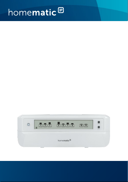
Fußbodenheizungsaktor –
12-fach, motorisch
Floor Heating Actuator –
12 channels, motorised
HmIP-FALMOT-C12
S. 2
p. 40
Page 2

Lieferumfang
Anzahl Bezeichnung
1 Homematic IP Fußbodenheizungsaktor
– 12-fach, motorisch
2 Schrauben 4,0 x 40 mm
2 Dübel 6 mm
1 Netzkabel
1 Bedienungsanleitung
Dokumentation © 2019 eQ-3 AG, Deutschland
Alle Rechte vorbehalten. Ohne schriftliche Zustimmung des
Herausgebers darf diese Anleitung auch nicht auszugsweise in
irgendeiner Form reproduziert werden oder unter Verwendung
elektronischer, mechanischer oder chemischer Verfahren vervielfältigt oder verarbeitet werden.
Es ist möglich, dass die vorliegende Anleitung noch drucktechnische Mängel oder Druckfehler aufweist. Die Angaben in dieser
Anleitung werden jedoch regelmäßig überprüft und Korrekturen
in der nächsten Ausgabe vorgenommen. Für Fehler technischer
oder drucktechnischer Art und ihre Folgen übernehmen wir keine
Haftung.
Alle Warenzeichen und Schutzrechte werden anerkannt.
Printed in Hong Kong
Änderungen im Sinne des technischen Fortschritts können ohne
Vorankündigung vorgenommen werden.
153627 (web)
Version 1.1 (06/2019)
Page 3
1
A
B
F
E
G
D
C
3
2
1
5
4
H
8
9
7
6
I
11
10
12
J
Page 4
2
K
L
3
M
120 mm
N
Page 5
456
Page 6
7
Channeltaste
drücken
press channel
button
Selecttaste
drücken
press select
button
Page 7

Inhaltsverzeichnis
1 Hinweise zur Anleitung ...................................................8
2 Gefahrenhinweise ............................................................8
3 Funktion und Geräteübersicht .................................... 11
4 Allgemeine Systeminformationen ..............................14
5 Montage ........................................................................... 14
5.1 Schraubmontage .................................................................14
5.2 Hutschienenmontage .........................................................15
6 Inbetriebnahme .............................................................. 16
6.1 Installationshinweise ...........................................................16
6.2 Installation .............................................................................17
6.3 Verhalten nach Einschalten der Netzspannung ............18
6.4 Anlernen ................................................................................19
6.4.1 Anlernen an den Homematic IP Wandthermostat.....19
6.4.2 Anlernen an die Homematic IP Multi IO Box ............. 20
6.4.3 Einen weiteren Fußbodenheizungsaktor hinzufügen 21
6.4.4 Anlernen an den Homematic IP Access Point ........... 22
7 Konfiguration über den Homematic IP
Wandthermostat .............................................................24
8 Manuelle Bedienung ......................................................29
9 Geräteverknüpfungen löschen .................................. 30
10 Fehlerbehebung ............................................................. 31
10.1 Befehl nicht bestätigt ..........................................................31
10.2 Duty Cycle ............................................................................31
10.3 Fehlercodes und Blinkfolgen ........................................... 32
10.3.1 Blinkfolgen der LED ......................................................... 32
10.3.2 Fehlercodes im Display ................................................... 33
11 Wiederherstellung der Werkseinstellungen .............. 35
12 Wartung und Reinigung ................................................36
13 Allgemeine Hinweise zum Funkbetrieb .....................36
14 Technische Daten ..........................................................37
7
Page 8
Hinweise zur Anleitung
1 Hinweise zur Anleitung
Lesen Sie diese Anleitung sorgfältig, bevor Sie Ihr Homematic IP Gerät in Betrieb nehmen. Bewahren Sie die Anleitung zum späteren Nachschlagen auf!
Wenn Sie das Gerät anderen Personen zur Nutzung überlassen, übergeben Sie auch diese Anleitung.
Benutzte Symbole:
Achtung!
Hier wird auf eine Gefahr hingewiesen.
Hinweis.
Dieser Abschnitt enthält zusätzliche wichtige Informationen!
2 Gefahrenhinweise
Önen Sie das Gerät nicht. Es enthält keine durch
den Anwender zu wartenden Teile. Das Önen
birgt die Gefahr eines Stromschlages. Lassen Sie
das Gerät im Fehlerfall von einer Fachkraft prüfen.
Betreiben Sie das Gerät nur in trockener sowie
staubfreier Umgebung, setzen Sie es keinem Einfluss von Feuchtigkeit, Vibrationen, ständiger
Sonnen- oder anderer Wärmeeinstrahlung, Kälte
und keinen mechanischen Belastungen aus.
8
Page 9
Gefahrenhinweise
Aus Sicherheits- und Zulassungsgründen (CE) ist
das eigenmächtige Umbauen und/oder Verändern des Gerätes nicht gestattet.
Verwenden Sie das Gerät nicht, wenn es von außen erkennbare Schäden, z. B. am Gehäuse, an
Bedienelementen oder an den Anschlussbuchsen
ausweist. Lassen Sie das Gerät im Zweifelsfall von
einer Fachkraft prüfen.
Das Gerät ist kein Spielzeug! Erlauben Sie Kindern
nicht damit zu spielen. Lassen Sie das Verpackungsmaterial nicht achtlos liegen.
Plastikfolien/-tüten, Styroporteile etc. können für
Kinder zu einem gefährlichen Spielzeug werden.
Bei Sach- oder Personenschäden, die durch unsachgemäße Handhabung oder Nichtbeachten
der Gefahrenhinweise verursacht werden, übernehmen wir keine Haftung. In solchen Fällen erlischt jeder Gewährleistungsanspruch! Für Folgeschäden übernehmen wir keine Haftung!
Das Gerät darf nur für ortsfeste Installationen verwendet werden. Das Gerät ist sicher innerhalb
einer festen Installation zu fixieren.
9
Page 10
Gefahrenhinweise
Der Aktor ist Teil der Gebäudeinstallation. Bei der
Planung und Errichtung sind die einschlägigen
Normen und Richtlinien des Landes zu beachten.
Arbeiten am 230-V-Netz dürfen nur von einer
Elektrofachkraft (nach VDE 0100) erfolgen. Dabei
sind die geltenden Unfallverhütungsvorschriften
zu beachten. Zur Vermeidung eines elektrischen
Schlages am Gerät, schalten Sie bitte die Netzspannung frei (Sicherungsautomat abschalten).
Bei Nichtbeachtung der Installationshinweise
können Brand oder andere Gefahren entstehen.
Beachten Sie beim Anschluss an die Geräteklemmen die hierfür zulässigen Leitungen und Leitungsquerschnitte.
Der Fußbodenheizungsaktor darf nur in Verbindung mit motorischen Stellantrieben (HmIP-VDMOT) betrieben werden.
Das Gerät ist nur für den Einsatz in Wohnbereichen, Geschäfts- und Gewerbebereichen sowie
in Kleinbetrieben bestimmt.
Jeder andere Einsatz, als der in dieser Bedienungsanleitung beschriebene, ist nicht bestimmungsgemäß und führt zu Gewährleistungs- und
Haftungsausschluss.
10
Page 11

Funktion und Geräteübersicht
3 Funktion und Geräteübersicht
Mit dem Homematic IP Fußbodenheizungsaktor können
Sie Ihre Fußbodenheizung Raum für Raum komfortabel
und bedarfsgerecht per Smartphone App oder mit dem
Homematic IP Wandthermostaten steuern und so die
Raumtemperatur auf Ihre individuellen Bedürfnisse anpassen.
Der Fußbodenheizungsaktor kann in Verbindung mit motorischen Stellantrieben (HmIP-VDMOT) zur Steuerung
einer Fußbodenheizung mit bis zu 12 Heizkreisen eingesetzt werden und lässt sich im Heiz- sowie Kühlmodus
betreiben (sofern Ihre Heizungsanlage diesen Betriebsmodus unterstützt).
Sie können das Gerät flexibel mit den mitgelieferten
Schrauben oder einfach auf einer Hutschiene montieren. Dank der sicheren Funkkommunikation zwischen
den Homematic IP Geräten beschränkt sich der Verdrahtungsaufwand auf ein Minimum.
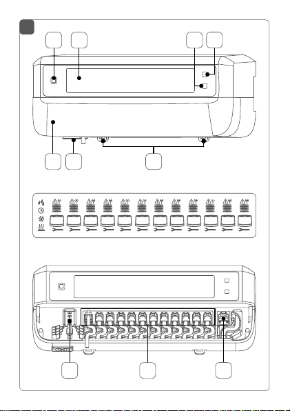
Geräteübersicht (s. Abbildung 1):
(A) Systemtaste (Anlerntaste und LED)
(B) LC-Display
(C) Selecttaste (Kanaltaste und LED)
(D) Channeltaste (Kanaltaste und LED)
(E) Abdeckung
(F) Anschlussbuchse 230 V~/50 Hz
11
Page 12
Funktion und Geräteübersicht
(G) Rastnasen für Hutschienenmontage
(H) Anschlussklemmen DC-IN 24 V
(I) Anschlussbuchsen für motorisierte Antriebe
(J) Anschlussbuchse für Erweiterungsbox (optional
verwendbar)
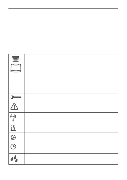
Displayübersicht (s. Abbildung 1):
Ventilpositionsanzeige:
Anzeige von Balken 1 – 5: Ventilposition > 80%
Anzeige von Balken 1 – 4: Ventilposition > 60%
Anzeige von Balken 1 – 3: Ventilposition > 40%
Anzeige von Balken 1 – 2: Ventilposition > 20%
Anzeige von Balken 1: Ventilposition > 0 %
Anzeige ohne Balken: Ventilposition = 0%
Maul-Schlüssel
Notbetrieb
Funkübertragung
Heizen
Kühlen
Externe Schaltuhr aktiv (in Verbindung mit einer Homematic IP Multi IO Box konfigurierbar)
Warnung für Betauung
12
Page 13
Funktion und Geräteübersicht
Weitere Informationen zu den Symbolen finden
Sie unter „10.3.2 Fehlercodes im Display“ auf Seite
33.
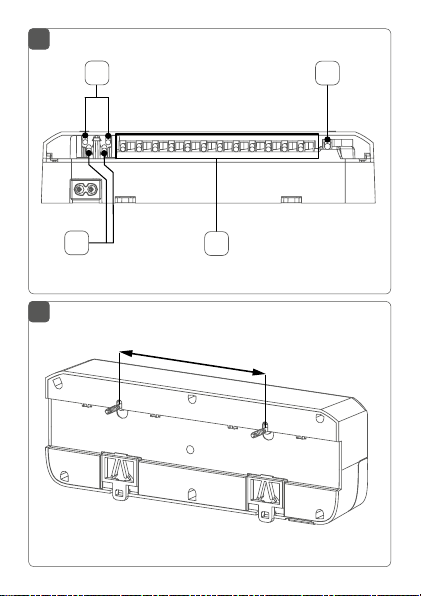
Kabeldurchführungen (s. Abbildung 2):
(K) Kabelführung für DC-IN
(L) Kabelführung für DC-IN
(M) Kabelführung für motorisierte Antriebe
(N) Kabelführung für Erweiterungsbox
Im Gegensatz zu konventionellen, thermischen
Stellantrieben kann der motorische Stellantrieb
jede beliebige Ventilposition, die vom Fußbodenheizungsaktor berechnet wird, anfahren, um die
gewünschte Raumtemperatur zu erreichen. Dadurch wird ein gleichmäßiger Wärmedurchfluss
und eine kontinuierliche Wärmeabgabe erzielt. Bei
einem Wechsel von konventionellen auf motorische Stellantriebe kann es in seltenen Fällen bei
einem hoch eingestellten Pumpendruck und geringen Ventilönungen zu Durchflussgeräuschen
am Heizkreisverteiler kommen. Dies können Sie
durch Veränderung der Pumpeneinstellungen
oder durch Anpassen der Parameter des Fußbodenheizungsaktors beheben.
13
Page 14

Allgemeine Systeminformationen
4 Allgemeine Systeminformationen
Dieses Gerät ist Teil des Homematic IP Smart-HomeSystems und kommuniziert über das Homematic IP
Funkprotokoll. Alle Geräte des Systems können komfortabel und individuell per Smartphone über die Homematic IP App konfiguriert werden. Alternativ haben Sie
die Möglichkeit, Homematic IP Geräte über die Zentrale CCU2/CCU3 oder in Verbindung mit vielen Partnerlösungen zu betreiben. Welcher Funktionsumfang
sich innerhalb des Systems im Zusammenspiel mit weiteren Komponenten ergibt, entnehmen Sie bitte dem
Homematic IP Anwenderhandbuch. Alle technischen
Dokumente und Updates finden Sie stets aktuell unter
www.eQ-3.de.
5 Montage
Sie können den Fußbodenheizungsaktor mit den mitgelieferten Schrauben frei an der Wand montieren oder auf
eine Hutschiene setzen.
5.1 Schraubmontage
Um den Fußbodenheizungsaktor mithilfe der Schrauben
zu montieren, gehen Sie wie folgt vor:
• Wählen Sie einen geeigneten Montageort in der
Nähe Ihres Heizkreisverteilers aus.
14
Page 15

Montage
Stellen Sie sicher, dass an der gewünschten Position in der Wand keine Leitungen verlaufen!
• Zeichnen Sie zwei der Bohrlöcher im Abstand
von 120 mm mit einem Stift an der Wand an (s.
Abbildung 3).
• Bohren Sie die vorgezeichneten Löcher mit einem geeigneten Bohrer von 6 mm Durchmesser.
• Montieren Sie den Fußbodenheizungsaktor durch
Eindrehen der mitgelieferten Dübel und Schrauben (s. Abbildung 3).
5.2 Hutschienenmontage
Um den Fußbodenheizungsaktor auf einer Hutschiene zu
montieren, gehen Sie wie folgt vor:
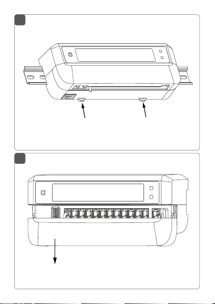
• Setzen Sie den Fußbodenheizungsaktor auf die
Hutschiene auf (s. Abbildung 4).
• Verrasten Sie den Fußbodenheizungsaktor, indem Sie die Rastnasen (G) nach oben drücken (s.
Abbildung 4).
• Achten Sie darauf, dass die Rastnasen komplett
einrasten und das Gerät fest auf der Schiene sitzt.
15
Page 16
Inbetriebnahme
6 Inbetriebnahme
6.1 Installationshinweise
Bitte lesen Sie diesen Abschnitt erst vollständig,
bevor Sie mit der Installation beginnen.
Für den Einbau des Fußbodenheizungsaktos in einen Stromkreisverteiler, muss das Gerät entsprechend VDE 0603, DIN 43871 (Niederspannungsunterverteilung (NSUV)), DIN 18015-x eingebaut
werden. In diesem Fall muss die Montage auf einer
Tragschiene (Hutschiene, DIN-Rail) lt. EN50022
erfolgen. Installation und Verdrahtung sind ent
sprechend VDE 0100 (VDE 0100-410, VDE 0100510 usw.) durchzuführen. Es sind die Vorschriften
der Technischen Anschlussbestimmungen (TAB)
des Energieversorgers zu berücksichtigen.
Beachten Sie bei der Installation die Gefahrenhinweise gemäß „2 Gefahrenhinweise“ auf Seite 8.
Zugelassene Kabelquerschnitte für die Kabelführungen
des Fußbodenheizungsaktors sind (s. Abbildung 2):
Kabeldurchführung Kabelquerschnitt [mm2]
1 (K) > 8,0
2 (L) > 5,5
3 (M) > 3,6
4 (N) > 4,4
16
-
Page 17

Inbetriebnahme
Zugelassene Leitungsquerschnitte zum Anschluss an die
(H)
Anschlussklemmen
des Fußbodenheizungsaktors
sind:
Starre Leitung: 0,12 – 0,50 mm
2
6.2 Installation
Sie können den Fußbodenheizungsaktor mit dem
beigelegten Netzkabel an eine 230 V-Steckdose
anschließen und so mit Spannung versorgen oder
Sie nutzen die Anschlussklemme (H) zum Anschluss von 24 V
Für die Installation des Fußbodenheizungsaktors gehen
Sie wie folgt vor:
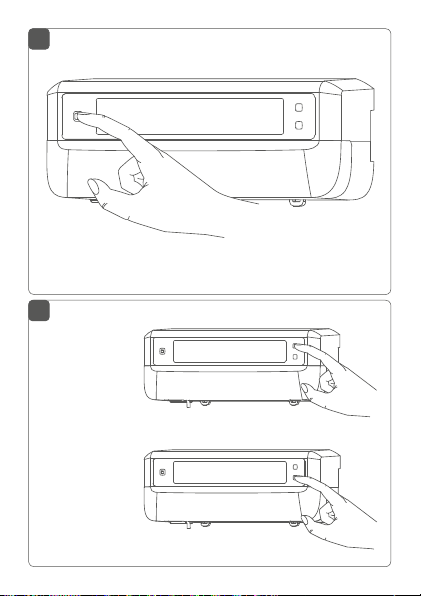
• Önen Sie die Abdeckung (E), indem Sie diese
nach unten abziehen (s. Abbildung 5).
• Schließen Sie (optional) ein Anschlusskabel mit
DC an die Anschlussklemme (H) an. Zum An-
24 V
schließen und Lösen der einzelnen Adern betätigen sie den orangen Betätigungsdrücker mit Hilfe
eines kleinen Schraubendrehers.
• Schließen Sie die Anschlusskabel Ihrer Ventilantriebe der Heizkreise an die Anschlussbuchsen (I)
an.
• Schließen Sie (optional) das Anschlusskabel Ihrer
Erweiterungsbox an die Anschlussbuchse (J) an.
• Schließen Sie die Abdeckung wieder, indem Sie
DC (SELV).
17
Page 18

Inbetriebnahme
die Abdeckung in die vorgesehenen Führungsschienen setzen und die Abdeckung nach oben
schieben.
• Stecken Sie das Netzkabel (optional) in eine
Steckdose.
6.3 Verhalten nach Einschalten der Netzspannung
Nach Einschalten der Netzspannung ist das Display (B) dauerhaft an.
In den ersten 3 Minuten nach dem Einschalten der Netzspannung befindet sich der Fußbodenheizungsaktor im
Anlernmodus, sofern er noch nicht angelernt wurde.
Weitere Informationen zum Anlernen finden Sie im nachfolgenden Abschnitt.
Alle angeschlossenen Ventilantriebe werden nacheinander vollständig geönet. Anschließend führen die Ventilantriebe eine Adaptierungsfahrt durch und ermitteln
dadurch die Ventilschließposition.
Nach erfolgreicher Adaptierfahrt wird jede Heizzone entsprechend der Ventilpositionsstellung im
Display angezeigt.
18
Page 19
Inbetriebnahme
6.4 Anlernen
Bitte lesen Sie diesen Abschnitt erst vollständig,
bevor Sie mit dem Anlernen beginnen.
Damit der Fußbodenheizungsaktor in Ihr System integriert werden und mit anderen Geräten kommunizieren
kann, muss er zunächst angelernt werden.
Sie können den Fußbodenheizungsaktor entweder direkt
an HomematicIP Geräte (wie bspw. an den Wandthermo
stat oder an die Multi IO Box) oder an den Homematic IP
Access Point anlernen. Beim direkten Anlernen erfolgt die
Konfiguration am Wandthermostat und beim Anlernen an
den Access Point über die HomematicIP App.
6.4.1 Anlernen an den Homematic IP
Wandthermostat
Halten Sie beim Anlernen einen Mindestabstand
von 50cm zwischen den Geräten ein.
Sie können den Anlernvorgang durch erneute
kurze Betätigung der Systemtaste (A) abbrechen
(s. Abbildung 6)
leuchten der LED (A) bestätigt.
Wenn kein Anlernen erfolgt, wird der Anlernmodus automatisch nach 3 Minuten beendet.
. Dies wird durch ein rotes Auf-
19
-
Page 20

Inbetriebnahme
Wenn Sie den Fußbodenheizungsaktor an einen HomematicIP Wandthermostat anlernen möchten, müssen die
beiden zu verknüpfenden Geräte in den Anlernmodus ge
bracht werden. Dafür gehen Sie wie folgt vor:
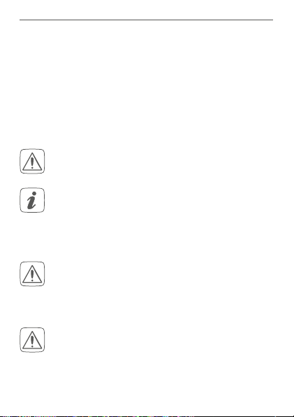
• Wählen Sie durch kurzes Drücken der Channel-
taste (D) den Kanal
aus, an den Sie ein Gerät anlernen möchten (s. Abbildung 7). Einmal Drücken
für Kanal 1, zweimal Drücken für Kanal 2, usw. Der
(B)
jeweilige Kanal wird im Display
angezeigt.
• Drücken Sie für 4 s auf die Systemtaste (A), bis die
LED schnell orange zu blinken beginnt (s. Abbil-
dung 6). Der Anlernmodus für den ausgewählten
Kanal ist für 3 Minuten aktiv.
• Drücken Sie die Systemtaste des Wandthermostats für mind. 4s, um den Anlernmodus zu aktivieren. Die LED blinkt orange.
Erfolgreiches Anlernen wird durch grünes Blinken der
LED (A) signalisiert.
War der Anlernvorgang nicht erfolgreich, leuchtet die
LED rot auf. Versuchen Sie es erneut.
6.4.2 Anlernen an die Homematic IP Multi IO Box
Wenn Sie den Fußbodenheizungsaktor an eine HomematicIP Multi IO Box anlernen möchten, müssen die beiden
zu verknüpfenden Geräte in den Anlernmodus gebracht
werden. Dafür gehen Sie wie folgt vor:
• Drücken Sie so oft kurz auf die Channeltaste (D),
20
-
Page 21

Inbetriebnahme
alle Kanäle im Display (B) angezeigt werden (s.
Abbildung 7).
• Drücken Sie für 4 s auf die Systemtaste (A), bis
die LED (A) schnell orange zu blinken beginnt (s.
Abbildung 6). Der Anlernmodus ist für 3 Minuten
aktiv.
• Drücken Sie die Systemtaste der Multi IO Box für
mind. 4 s, um den Anlernmodus zu aktivieren. Die
LED blinkt orange.
Erfolgreiches Anlernen wird durch grünes Blinken der
LED (A) signalisiert.
War der Anlernvorgang nicht erfolgreich, leuchtet die
LED rot auf. Versuchen Sie es erneut.
6.4.3 Einen weiteren Fußbodenheizungsaktor
hinzufügen
Um dem System bzw. den bestehenden Geräten einen
weiteren Fußbodenheizungsaktor hinzuzufügen, gehen
Sie wie folgt vor:
• Lernen Sie zunächst den neuen Fußbodenheizungsaktor an den bestehenden Fußbodenheizungsaktor an. Bringen Sie dafür den bestehenden Fußbodenheizungsaktor über einen langen
Tastendruck (mind. 4 s) der Systemtaste (A) in den
Anlernmodus (s. Abbildung 6).
• Aktivieren Sie den Anlernmodus am neuen Fußbodenheizungsaktor über einen langen Tasten-
21
Page 22

Inbetriebnahme
druck (mind. 4 s) der Systemtaste (A).
Erfolgreiches Anlernen wird durch grünes Blinken
der Geräte-LED (A) signalisiert. War der Anlernvorgang nicht erfolgreich, leuchtet die LED rot
auf. Versuchen Sie es erneut.
• Lernen Sie den neuen Fußbodenheizungsaktor
ggf. an weitere Homematic IP Geräte, wie z. B.
an einen Wandthermostat oder eine Multi IO Box,
an, indem Sie zunächst den Fußbodenheizungsaktor und dann das anzulernende Gerät in den
Anlernmodus versetzen. Weitere Informationen
dazu entnehmen Sie bitte der jeweiligen Bedienungsanleitung.
6.4.4 Anlernen an den Homematic IP Access Point
Richten Sie zunächst Ihren Homematic IP Access
Point über die Homematic IP App ein, um weitere
Homematic IP Geräte im System nutzen zu können. Ausführliche Informationen dazu finden Sie
in der Bedienungsanleitung des Access Points.
Sie können das Gerät an den Access Point oder an
die Zentrale CCU2/CCU3 anlernen. Weitere Informationen dazu entnehmen Sie bitte dem Homematic IP Anwenderhandbuch (zu finden im Downloadbereich unter www.eQ-3.de).
22
Page 23

Inbetriebnahme
Zum Anlernen des Fußbodenheizungsaktors an den Access Point gehen Sie wie folgt vor:
• Önen Sie die Homematic IP App auf Ihrem
Smartphone.
• Wählen Sie den Menüpunkt „Gerät anlernen“ aus.
• Drücken Sie kurz auf die Systemtaste (A), bis die
LED (A) langsam orange zu blinken beginnt (s.
Abbildung 6). Der Anlernmodus für den ausgewählten Kanal ist für 3 Minuten aktiv.
Sie können den Anlernmodus manuell für weitere
3 Minuten starten, indem Sie die Systemtaste (A)
kurz drücken (s. Abbildung 6).
• Das Gerät erscheint automatisch in der Homematic IP App.
• Zur Bestätigung geben Sie in der App die letzten
vier Ziern der Gerätenummer (SGTIN) ein oder
scannen Sie den QR-Code. Die Gerätenummer
finden Sie auf dem Aufkleber im Lieferumfang
oder direkt am Gerät.
• Warten Sie, bis der Anlernvorgang abgeschlossen
ist.
• Zur Bestätigung eines erfolgreichen Anlernvorgangs leuchtet die LED grün. Das Gerät ist nun
einsatzbereit.
• Leuchtet die LED rot, versuchen Sie es erneut.
• Wählen Sie die gewünschte Lösung für Ihr Gerät
23
Page 24

Konfiguration über den Homematic IP Wandthermostat
aus.
• Vergeben Sie in der App einen Namen für das Gerät und ordnen Sie es einem Raum zu.
7 Konfiguration über den Homema-
tic IP
Wandthermostat
Die Konfiguration des Homematic IP Fußbodenheizungsaktors ist mit dem Homematic IP Wandthermostat (HmIP-WTH-2), über den Homematic
IP Access Point in Verbindung mit der Smartpho
n
e App oder über die WebUI der Zentrale CCU2/
CCU3 möglich.
Um den Fußbodenheizungsaktor über den Wandthermostat zu konfigurieren, gehen Sie wie folgt vor:
• Drücken Sie lange auf das Stellrad des Wandthermostats, um das Konfigurationsmenü zu önen.
• Wählen Sie durch Drehen des Stellrads das Symbol „
durch kurzes Drücken des Stellrads.
• Wählen Sie mit dem Stellrad den gewünschten
Fußbodenheizungsaktor („FALx“) aus.
• Wählen Sie aus, ob Sie Geräteparameter („UnP1/
UnP2“) oder Kanalparameter („ChAn“) konfigurieren wollen.
24
“ aus und bestätigen Sie die Auswahl
-
Page 25

Konfiguration über den Homematic IPWandthermostat
Die Einstellungen, die Sie unter „UnP1/UnP2“ vornehmen können, betreen das gesamte Gerät.
Die Einstellungen, die Sie unter „ChAn“ vornehmen können, betreen die einzelnen Kanäle des
Geräts.
• Stellen Sie Entkalkungsfahrten, Luftfeuchtigkeitsgrenzen und Details zum Heiz- bzw. Kühlmodus
etc. ganz individuell nach dem folgenden Schema ein.
Geräteparameter UnP1:
Parameter Index Wert Bedeutung
Wochentag für
Entkalkungsfahrt
Zeitpunkt für
Entkalkungsfahrt
P010 0
P011 0
Sonntag
1
Montag
2
Dienstag
3
Mittwoch
4
Donnerstag
5
Freitag
6
Samstag (default)
00:00 Uhr
1
00:30 Uhr
2
01:00 Uhr
...
…
22
11:00 Uhr (default)
...
…
46
23:00 Uhr
47
23:30 Uhr
25
Page 26

Konfiguration über den Homematic IPWandthermostat
Frostschutztemperatur
Notbetrieb im
Heizmodus
Notbetrieb im
Kühlmodus
P024 3
P026 0
P032 0
Frostschutz inaktiv
4
2,0 °C
5
2,5 °C
…
…
16
8,0 °C (default)
…
…
19
9,5 °C
20
10,0 °C
0 %
1
1 %
…
…
25
25 % (default)
…
…
99
99 %
100
100 %
0 % (default)
1
1 %
…
…
99
99 %
100
100 %
Geräteparameter UnP2:
Parameter Index Wert Bedeutung
Dauer/Länge der
externen
Pumpenschutzfunktion
26
P007 128
129
...
133
...
138
0 Minuten
1 Minute
...
5 Minuten (default)
...
10 Minuten
Page 27

Konfiguration über den Homematic IPWandthermostat
Zeitintervall für
die
externe Pumpenschutzfunktion
P051 225
226
...
238
...
251
252
1 Tag
2 Tage
...
14 Tage (default)
...
27 Tage
28 Tage
Kanalparameter ChAn:
Parameter Index Wert Bedeutung
Minimale Fußbodentemperatur in Verbindung mit einem
Fußboden-Temperatursensor
Luftfeuchtigkeitsgrenze
P045 10
11
…
38
…
59
60
P050 40
…
80
168
…
188
…
208
5.0 °C
5.5 °C
…
19.0 °C (default)
…
29.5 °C
30.0 °C
40 %; Luftfeuchtig-
keitsgrenze inaktiv
…
80 %; Luftfeuchtigkeitsgrenze inaktiv
40 %; Luftfeuchtigkeitsgrenze aktiv
…
60 %; Luftfeuchtigkeitsgrenze
aktiv (default)
…
80 %; Luftfeuchtigkeitsgrenze aktiv
27
Page 28

Konfiguration über den Homematic IPWandthermostat
Kühlen im Kühlmodus aktiv/
inaktiv
Heizen im Heizmodus aktiv/
inaktiv
Auswahl der
häuslichen Gegebenheiten
P052 0
P053 0
P055 0
Kühlen im Kühlmodus inaktiv
1
Kühlen im
Kühlmodus aktiv
(default)
Heizen im Heizmodus inaktiv
1
Heizen im
Heizmodus aktiv
(default)
FBH Standard
(default)
1
FBH Niedrigenergie
Weiterführende Informationen zur Konfiguration
können Sie der Bedienungsanleitung des Wandther
mostats (HmIP-WTH-2) entnehmen.
28
-
Page 29

Manuelle Bedienung
8 Manuelle Bedienung
Zu Installations- und Testzwecken können die Adaptierfahrten an den einzelnen Heizzonen manuell neu gestartet oder einzelne Heizzonen auf- bzw. zugefahren
werden.
Um eine Adaptierfahrt manuell zu starten, gehen Sie wie
folgt vor:
• Wählen Sie mit der Channeltaste (D) den gewünschten Kanal aus (s. Abbildung 7).
• Drücken Sie die Selecttaste (C) solange, bis im
Display (B) der Maul-Schlüssel beim ausgewählten
Kanal erscheint (s. Abbildung 7).
Soll die Adaptierfahrt an allen Heizzonen neu gestartet werden, können Sie über die Channeltaste
auch alle Kanäle auswählen (so oft drücken, bis
alle Kanäle im Display erscheinen) und die Selecttaste solange betätigen bis der Maul-Schlüssel bei
Heizzone „1“ im Display erscheint.
Um eine Heizzone manuell auf- bzw. zuzufahren, gehen
Sie wie folgt vor:
• Wählen Sie mit der Channeltaste (D) den gewünschten Kanal aus (s. Abbildung 7).
• Drücken Sie die Selecttaste (C) kurz (s. Abbildung
7).
29
Page 30

Geräteverknüpfungen löschen
Die Heizzone önet bzw. schließt nun für 15 Minuten
das Ventil der Heizzone. Anschließend wird die Heizzone
wieder normal geregelt.
Soll das Ventil aller Heizzonen gleichzeitig geönet bzw. geschlossen werden, wählen Sie alle
Kanäle aus und drücken Sie die Selecttaste (C)
kurz.
9 Geräteverknüpfungen löschen
Um die Geräteverknüpfungen zwischen einem Fußbodenheizungsaktor und einem Wandthermostat zu löschen, gehen Sie wie folgt vor:
• Wählen Sie über die Channeltaste (D) des Fußbodenheizungsaktors den Kanal aus, an den der
Wandthermostat angelernt ist (s. Abbildung 7).
• Drücken Sie
taste des Fußbodenheizungsaktors gleichzeitig
so lange, bis die LED
• Stellen Sie die Werkseinstellungen des Wandthermostats wieder her (weitere Informationen dazu
entnehmen Sie bitte der Bedienungsanleitung
des Wandthermostats).
30
die Systemtaste (A) und
(A)
grün aufleuchtet.
die Channel-
Page 31

Fehlerbehebung
10 Fehlerbehebung
10.1 Befehl nicht bestätigt
Bestätigt mindestens ein Empfänger einen Befehl nicht,
leuchtet zum Abschluss der fehlerhaften Übertragung
(A)
die LED
kann eine Funkstörung sein (s. „13 Allgemeine Hinweise
zum Funkbetrieb“ auf Seite 36). Die fehlerhafte Übertragung kann folgende Ursachen haben:
10.2 Duty Cycle
Der Duty Cycle beschreibt eine gesetzlich geregelte Begrenzung der Sendezeit von Geräten im 868 MHz-Bereich. Das Ziel dieser Regelung ist es, die Funktion aller im
868 MHz-Bereich arbeitenden Geräte zu gewährleisten.
In dem von uns genutzten Frequenzbereich 868 MHz beträgt die maximale Sendezeit eines jeden Gerätes 1 % einer Stunde (also 36 Sekunden in einer Stunde). Die Geräte
dürfen bei Erreichen des 1 %-Limits nicht mehr senden,
bis diese zeitliche Begrenzung vorüber ist. Gemäß dieser
Richtlinie, werden Homematic IP Geräte zu 100 % normenkonform entwickelt und produziert.
Im normalen Betrieb wird der Duty Cycle in der Regel
nicht erreicht. Dies kann jedoch in Einzelfällen bei der In-
rot auf. Grund für die fehlerhafte Übertragung
• Empfänger nicht erreichbar,
• Empfänger kann Befehl nicht ausführen (Lastausfall, mechanische Blockade etc.) oder
• Empfänger defekt.
31
Page 32

Fehlerbehebung
betriebnahme oder Erstinstallation eines Systems durch
vermehrte und funkintensive Anlernprozesse der Fall sein.
Eine Überschreitung des Duty-Cycle-Limits wird durch
(A)
einmal langes rotes Blinken der LED
angezeigt und
kann sich durch temporär fehlende Funktion des Gerätes
äußern. Nach kurzer Zeit (max. 1 Stunde) ist die Funktion
des Gerätes wiederhergestellt.
10.3 Fehlercodes und Blinkfolgen
10.3.1 Blinkfolgen der LED
Blinkcode Bedeutung Lösung
Kurzes oranges
Blinken
Funkübertragung/Sendeversuch/Datenübertragung
Warten Sie, bis
die Übertragung
beendet ist.
1x langes
grünes Leuchten
1x langes rotes
Leuchten
32
Vorgang bestätigt
Vorgang fehlgeschlagen oder
Duty-CycleLimit erreicht
Sie können mit
der Bedienung
fortfahren.
Versuchen Sie es
erneut („10.1 Befehl
nicht bestätigt“ auf
Seite 31 oder
„10.2 Duty Cycle“
auf Seite 31).
Page 33

Fehlerbehebung
Kurzes oranges
Blinken (alle
10 s)
6x langes rotes
Blinken
1x oranges und
1x grünes
Leuchten
Anlernmodus
aktiv
Gerät defekt Achten Sie auf die
Testanzeige Nachdem die Test-
Geben Sie die
letzten vier Ziern
der GeräteSeriennummer zur
Bestätigung ein (s.
„6.4 Anlernen“ auf
Seite 19).
Anzeige in Ihrer
App oder wenden
Sie sich an Ihren
Fachhändler.
anzeige erloschen
ist, können Sie
fortfahren.
10.3.2 Fehlercodes im Display
Blinkcode Bedeutung Lösung
Maulschlüssel
blinkt im 0,5 s
Raster
Adaptierfahrt an
der Heizzone
konnte nicht
ausgeführt
werden.
Prüfen Sie, ob
der Stellantrieb
korrekt auf das
Ventil montiert
wurde und ob der
Anschlussstecker in
die entsprechende
Anschlussbuchse
gesteckt wurde.
33
Page 34

Fehlerbehebung
Ausrufezeichen blinkt im
0,5 s Raster
Antenne blinkt
im 0,5 s Raster
Ausrufezeichen und Antenne werden
eingeblendet
34
Die Heizzone
befindet sich im
Notbetrieb.
Funkverbindung
zum Wandthermostat gestört
Adaptierfahrt
abgeschlossen
(kein Wandthermostat an
diese Heizzone
angelernt)
Funktest durchführen, Wandthermostat ggf. neu positionieren, Batterien
des Wandthermostats wechseln
oder defekten
Wandthermostat
austauschen.
Position des Wandthermostats verändern oder einen
Repeater einsetzen
(s. „10.1 Befehl
nicht bestätigt“ auf
Seite 31“).
Wandthermostat an Heizzone
anlernen (s. „6.4.1
Anlernen an den
Homematic IP
Wandthermostat“ auf Seite
19 bzw. „6.4.4
Anlernen an den
Homematic IP
Access Point“ auf
Seite 22.
Page 35

Wiederherstellung der Werkseinstellungen
Aktivierung des
Feuchteeingangs an der
Multi IO Box
Lüften Sie und
stellen Sie ggf. von
Kühl- auf Heizbetrieb um.
11 Wiederherstellung der Werksein-
stellungen
Die Werkseinstellungen des Geräts können wiederhergestellt werden. Dabei gehen alle Einstellungen verloren.
Um die Werkseinstellungen des Fußbodenheizungsaktors
wiederherzustellen, gehen Sie wie folgt vor:
• Drücken Sie für 4 s auf die Systemtaste (A), bis
die LED (A) schnell orange zu blinken beginnt (s.
Abbildung 6).
• Lassen Sie die Systemtaste wieder los.
• Drücken Sie die Systemtaste erneut für 4 s, bis die
LED grün aufleuchtet.
• Lassen Sie die Systemtaste wieder los, um das
Wiederherstellen der Werkseinstellungen abzuschließen.
Das Gerät führt einen Neustart durch. Nach dem Neustart
können Sie das Gerät wieder in Ihr Homematic IP System
integrieren.
35
Page 36

Wartung und Reinigung
12 Wartung und Reinigung
Das Gerät ist wartungsfrei. Überlassen Sie eine Reparatur einer Fachkraft.
Reinigen Sie das Gerät mit einem weichen, sauberen,
trockenen und fusselfreien Tuch. Verwenden Sie keine
lösemittelhaltigen Reinigungsmittel, das Kunststogehäuse und die Beschriftung können dadurch angegrien
werden.
13 Allgemeine Hinweise zum Funk-
betrieb
Die Funk-Übertragung wird auf einem nicht exklusiven
Übertragungsweg realisiert, weshalb Störungen nicht
ausgeschlossen werden können. Weitere Störeinflüsse
können hervorgerufen werden durch Schaltvorgänge,
Elektromotoren oder defekte Elektrogeräte.
Die Reichweite in Gebäuden kann stark von der
im Freifeld abweichen. Außer der Sendeleistung
und den Empfangseigenschaften der Empfänger
spielen Umwelteinflüsse wie Luftfeuchtigkeit neben baulichen Gegebenheiten vor Ort eine wichtige Rolle.
Hiermit erklärt die eQ-3 AG, Maiburger Str. 29, 26789
Leer, Deutschland, dass der Funkanlagentyp Homema-
36
Page 37

Technische Daten
ticIP HmIP-FALMOT-C12 der Richtlinie 2014/53/EU entspricht. Der vollständige Text der EU-Konformitätserklärung ist unter der folgenden Internetadresse verfügbar:
www.eq-3.de
14 Technische Daten
Geräte-Kurzbezeichnung: HmIP-FALMOT-C12
Konstruktion des Regelund Steuergerätes (RS): Unabhängig
Anzahl Heizzonen: 12
Versorgungsspannung
Anschlussbuchse (F): 230 V/50 Hz
Anschlussbuchse (H): 24 V
Stromaufnahme
Anschlussbuchse (F): 0,500 A max.
Anschlussbuchse (H): 0,375 A max.
Leitungsart u. -querschnitt
Anschlussbuchse (H): starre und flexible
Kabelquerschnitt Klemmanschluss (K): > 8,0 mm
Kabelquerschnitt Klemmanschluss (L): > 5,5 mm
Kabelquerschnitt Klemmanschluss (M): > 3,6 mm
Kabelquerschnitt Klemmanschluss (N): > 4,4 mm
montiertes elektronisches RS für
Aufbaumontage
DC/SELV
Leitung,
0,12 - 0,5 mm²
37
Page 38

Technische Daten
Schutzart: IP20
Schutzklasse:
II @ 230 V / III @ 24V
Umgebungstemperatur: 0 bis 50 °C
Wirkungsweise: Typ 1
Stehstoßspannung: 2500 V
Verschmutzungsgrad: 2
Temperatur Glühdrahtprüfung: 850 °C
Temperatur Kugeldruckprüfung: 125 °C
PTI-Wert des Gehäusematerials: IIIb mit 100 < CTI <
175
Abmessungen (B x H x T ): 242 x 85 x 52 mm
Gewicht: 440 g
Funk-Frequenzband: 868,0-868,60 MHz
869,4-869,65 MHz
Max. Funk-Sendeleistung: 10 dBm
Empfängerkategorie: SRD category 2
Typ. Funk-Freifeldreichweite: 320 m
Duty Cycle: < 1% pro h / < 10%
pro h
Software-Klasse: Klasse A
Technische Änderungen vorbehalten.
38
Page 39

Entsorgungshinweis
Gerät nicht im Hausmüll entsorgen! Elektronische Geräte sind entsprechend der Richtlinie
über Elektro- und Elektronik-Altgeräte über die
örtlichen Sammelstellen für Elektronik-Altgeräte
zu entsorgen.
Konformitätshinweis
Das CE-Zeichen ist ein Freiverkehrszeichen, das
sich ausschließlich an die Behörden wendet und
keine Zusicherung von Eigenschaften beinhaltet.
Bei technischen Fragen zum Gerät wenden Sie
sich bitte an Ihren Fachhändler.
Technische Daten
39
Page 40

Package contents
Quantity Description
1 Homematic IP Floor Heating Actuator – 12
channels, motorised
2 Screws 4.0 x 40 mm
2 Plugs 6 mm
1 Power cable
1 Operating manual
Documentation © 2019 eQ-3 AG, Germany.
All rights reserved. This manual may not be reproduced in any format, either in whole or in part, nor may it be duplicated or edited
by electronic, mechanical or chemical means, without the written
consent of the publisher.
Typographical and printing errors cannot be excluded. However,
the information contained in this manual is reviewed on a regular
basis and any necessary corrections will be implemented in the
next edition. We accept no liability for technical or typographical
errors or the consequences thereof.
All trademarks and industrial property rights are acknowledged.
Printed in Hong Kong
Changes may be made without prior notice as a result of technical advances.
153627 (web)
Version 1.1 (06/2019)
40
Page 41

Table of contents
1 Information about this manual....................................42
2 Hazard information ........................................................42
3 Function and device overview ....................................45
4 General system information ........................................ 47
5 Mounting ......................................................................... 48
5.1 Screw mounting.................................................................. 48
5.2 DIN rail mount ..................................................................... 49
6 Start-up ........................................................................... 49
6.1 Installation instructions ..................................................... 49
6.2 Installation ............................................................................ 50
6.3 Behaviour after switching on the mains voltage ..........51
6.4 Teaching-in .......................................................................... 52
6.4.1 Pairing with a Homematic IP Wall Thermostat .......... 52
6.4.2 Pairing with a Homematic IP Multi IO Box ................. 53
6.4.3 Adding a new floor heating actuator ........................... 54
6.4.4 Teaching-in to the Homematic IP Access Point ........55
7 Configuration via the HomematicIP
Wall Thermostat .............................................................57
8 Manual operation ...........................................................62
9 Delete device connections ......................................... 64
10 Troubleshooting ............................................................ 64
10.1 Command not confirmed ................................................. 64
10.2 Duty cycle ............................................................................ 65
10.3 Error codes and flashing sequences .............................. 66
10.3.1 Flashing sequences of the LED ..................................... 66
10.3.2 Error codes in the display ................................................67
11 Restore factory settings ............................................... 69
12 Maintenance and cleaning .......................................... 69
13 General information about radio operation .............70
14 Technical specifications ................................................ 71
41
Page 42

Information about this manual
1 Information about this manual
Please read this manual carefully before beginning operation with your Homematic IP component. Keep the
manual so you can refer to it at a later date if you need to.
If you hand over the device to other persons for use,
please hand over this manual as well.
Symbols used:
Attention!
This indicates a hazard.
Please note:
This section contains important additional information.
2 Hazard information
Do not open the device. It does not contain any
parts that can be maintained by the user. If you
have any doubts, have the device checked by an
expert.
The device may only be operated in dry and dustfree environment and must be protected from
the eects of moisture, vibrations, solar or other
methods of heat radiation, cold and mechanical
loads.
42
Page 43

Hazard information
For safety and licensing reasons (CE), unauthorized change and/or modification of the device is
not permitted.
Do not use the device if there are signs of damage to the housing, control elements or connecting sockets, for example. If you have any doubts,
have the device checked by an expert.
The device is not a toy; do not allow children to
play with it. Do not leave packaging material lying
around. Plastic films/bags, pieces of polystyrene,
etc. can be dangerous in the hands of a child.
We do not assume any liability for damage to
property or personal injury caused by improper
use or the failure to observe the hazard information. In such cases, any claim under warranty is
extinguished! For consequential damages, we assume no liability!
The device may only be used for fixed installations. The device must be securely attached within a fixed installation.
43
Page 44

Hazard information
The actuator is part of the building installation.
The relevant national standards and directives
must be taken into consideration during planning
and set-up. Only qualified electricians (to VDE
0100) are permitted to carry out work on the 230
V mains. Applicable accident prevention regulations must be complied with while such work is
being carried out. To avoid electric shocks from
the device, please disconnect the mains voltage
(trip the miniature circuit-breaker). Non-compliance with the installation instructions can cause
fire or introduce other hazards.
When connecting to the device terminals, take
the permissible cables and cable cross sections
into account.
The floor heating actuator may only be operated
in conjunction with motorised actuators (HmIPVDMOT).
The device may only be operated within residential buildings.
Using the device for any purpose other than that
described in this operating manual does not fall
within the scope of intended use and shall invalidate any warranty or liability.
44
Page 45

Function and device overview
3 Function and device overview
The Homematic IP Floor Heating Actuator oers comfortable and demand-based room-by-room control of
your floor heating system via smartphone app or the
Homematic IP Wall Thermostat, according to your personal needs.
The floor heating actuator can be used in conjunction
with motorised actuators (HmIP-VDMOT) to control a
floor heating system with up to 12 heating circuits and
can be operated in heating and cooling mode (provided
your heating system supports this mode).
You can flexibly mount the device using the supplied
screws or a DIN rail. With the secure radio communication between the Homematic IP devices, the wiring eort
is kept to a minimum.
Device overview (see figure 1):
(A) System button (teach-in/pairing button and LED)
(B) LC Display
(C) Select button (channel button and LED)
(D) Channel button (channel button and LED)
(E) Cover
(F) Connecting socket 230 V~/50 Hz
(G) Spring latch for DIN rail mounting
(H) Terminals DC-IN 24 V
(I) Connecting sockets for motorised drives
(J) Connecting socket for expansion box (can be
used optionally)
45
Page 46

Function and device overview
Display overview (see figure 1):
Valve position indicator:
Display of bars 1 – 5: Valve position > 80%
Display of bars 1 – 4: Valve position > 60%
Display of bars 1 – 3: Valve position > 40%
Display of bars 1 – 2: Valve position > 20%
Display of bar 1: Valve position > 0 %
Display without bars: Valve position = 0%
Open-end wrench
Emergency operation
Radio transmission
Heating
Cooling
External timer active (configurable in conjunction with a Homematic IP Multi IO Box)
Warning about condensation
For further information regarding the symbols
see „10.3.2 Error codes in the display“ on page
67.
46
Page 47

General system information
Cable bushings (see figure 2):
(K) Cable bushing for DC-IN
(L) Cable bushing for DC-IN
(M) Cable routing for motorised drives
(N) Cable routing for extension box
Unlike conventional thermal actuators, the motorised actuator can move to any valve position
calculated by the floor heating actuator in order
to reach the desired room temperature. This results in an even heat flow and continuous heat
dissipation. When switching from conventional to
motorised actuators, flow noises may occur in
rare cases at the heating circuit distributor if the
pump pressure setting is high and the valve openings are small. You can correct this by changing
the pump settings or by adjusting the parameters
of the floor heating actuator.
4 General system information
This device is part of the Homematic IP smart home system and works with the Homematic IP radio protocol. All
devices of the system can be configured comfortably and
individually with the Homematic IP smartphone app. Alternatively, you can operate the Homematic IP devices
via the Central Control Unit CCU2/CCU3 or in connection with various partner solutions. The available func-
47
Page 48

Mounting
tions provided by the system in combination with other
components are described in the Homematic IP User
Guide. All current technical documents and updates are
provided at www.eQ-3.com.
5 Mounting
You can flexibly mount the floor heating actuator to a
wall using the supplied screws or to a DIN rail.
5.1 Screw mounting
For mounting the floor heating actuator using screws,
please proceed as follows:
• Please select a suitable mounting location close
to your heating manifold.
Make sure that no electricity or similar lines run in
the wall at this location!
• Use a pen to mark the positions of the two bore
holes with a distance of 120 mm on the wall (see
figure 3).
• Use a suitable bit to drill the 6 mm holes as illustrated.
• Use the supplied screws and plugs to fasten the
floor heating actuator (see figure 3).
48
Page 49

Start-up
5.2 DIN rail mount
For mounting the floor heating actuator to a DIN rail,
please proceed as follows:
• Place the floor heating actuator onto the DIN rail
(see figure 4).
• Latch the floor heating actuator by pressing the
spring latches (G) upwards (see figure 4).
• Make sure that the spring latches are completely
latched and that the device is seated solidly on
the rail.
6 Start-up
6.1 Installation instructions
Please read this entire section before starting to
install the device.
For installing the floor heating actuator into a
power distribution panel it has to be mounted in
accordance with VDE 0603, DIN 43871 (low-voltage sub-distribution board), DIN 18015-x. In this
case, the installation must be made on a mounting rail (DIN rail) according to EN50022. Installation and wiring have to be performed according
to VDE 0100 (VDE 0100-410, VDE 0100-510 etc.).
Please consider the technical connection requirements (TAB) of your energy supplier.
49
Page 50

Start-up
Please observe the hazard information in section
„2 Hazard information“ on page 42.
Permitted cable cross sections for the cable bushings of
the floor heating actuator are (see figure 2):
Cable bushings Cable cross section [mm]
1 (K) > 8.0
2 (L) > 5.5
3 (M) > 3.6
4 (N) > 4.4
Permitted cable cross sections for connecting to the
connecting terminals (H) of the floor heating actuator:
Rigid cable: 0.12 – 0.50 mm
6.2 Installation
You can connect the floor heating actuator to a
230 V socket using the supplied mains cable and
thus provide it with power, or you can use the
connection terminal (H) to connect 24 V
(SELV).
To install the floor heating actuator, please proceed as
follows:
50
DC
Page 51

Start-up
• Open the cover (E) by pulling it downwards (see
figure 5).
• Connect (optionally) a 24 V
DC connecting cable
to the terminal (H). To connect and disconnect
the individual wires, press the orange actuator
button using a small screwdriver.
• Connect the connecting cables of the valve actuators of your heating circuits to the connecting
sockets (I).
• Connect (optionally) the connecting cable of
your expansion box to the connecting socket (J).
• Close the cover again by placing the cover in the
guide rail provided and pushing the cover upwards.
• Plug the power cable (optional) into a socket.
6.3 Behaviour after switching on the mains
voltage
After the mains voltage is switched on, the display
(B) lights up permanently.
If the device has not yet been connected, teach-in mode
will be activated during the first 3 minutes after the mains
voltage has been switched on. You will find further information about connecting your device in the next section.
All connected valve actuators are opened fully one after
the other. The valve actuators then carry out an adaptation run to determine the valve closing position.
51
Page 52

Start-up
After a successful adaptation run, each heating
zone is shown in the display according to the valve position.
6.4 Teaching-in
Please read this entire section before starting
the teach-in procedure.
To integrate the floor heating actuator into your system
and enable it to communicate with other devices, you
must teach it in first.
You can either pair the floor heating actuator directly with
other Homematic IP devices (e.g. the wall thermostat or
the Multi IO Box) or teach it in to the Homematic IP Ac
cess Point. After pairing, the device is configured at the
wall thermostat. After teaching-in to the Access Point, the
device is configured via the Homematic IP app.
6.4.1 Pairing with a Homematic IP Wall Thermostat
Please make sure you maintain a distance of at
least 50cm between the devices.
You can cancel the pairing procedure by briefly
pressing the system button (A) again. This will be
indicated by the device LED (A)lighting red.
If no pairing operations are carried out, pairing
mode is exited automatically after 3 seconds.
52
-
Page 53

Start-up
If you want to pair the floor heating actuator with a
Homematic IP Wall Thermostat, the pairing mode of both
devices has to be activated first. To do this, proceed as
follows:
• Select the channel to which you would like to pair
a device by pressing the channel button (D) briefly (see figure 7). Press once for channel 1, press
twice for channel 2, etc. The channel is question
is shown in the display (B).
• Press and hold down the system button (A) for
4 seconds until the LED quickly starts flashing
orange (see figure 6). The pairing mode of the
selected channel remains activated for 3 minutes.
• Press and hold down the system button of the
wall thermostat for at least 4 seconds to activate
the pairing mode. The device LED flashes orange.
The device LED (A) lights up green to indicate that pairing
has been successful. If pairing failed, the device LED (A)
lights up red. Please try again.
6.4.2 Pairing with a Homematic IP Multi IO Box
If you want to pair the floor heating actuator with a
Homematic IP Multi IO Box, the pairing mode of both
devices has to be activated first. To do this, proceed as
follows:
• Keep pressing the channel button (D) briefly until all channels are shown in the display (B) (see
53
Page 54

Start-up
figure 7).
• Press and hold down the system button (A) for 4
seconds until the LED (A) quickly starts flashing
orange (see figure 6). Pairing mode remains activated for 3 minutes.
• Press and hold down the system button of the
Multi IO Box for at least 4 seconds to activate the
pairing mode. The device LED flashes orange.
The device LED (A) lights up green to indicate that pairing
has been successful. If pairing failed, the device LED (A)
lights up red. Please try again.
6.4.3 Adding a new floor heating actuator
To add a new floor heating actuator to the system or to
the existing devices, please proceed as follows:
• First pair the new floor heating actuator with an
existing one. Activate the pairing mode of the existing floor heating actuator. Therefore, press and
hold down the system button (A) for at least 4
seconds (see figure 6).
• Activate the pairing mode of the new floor heating
actuator. Press and hold down the system button
(A) for at least 4 seconds.
The device LED (A) lights up green to indicate that
pairing has been successful. If pairing failed, the
device LED (A) lights up red. Please try again.
54
Page 55

Start-up
• You can add the new floor heating actuator to
other devices such as the wall thermostat or the
Multi IO Box. Simply activate the pairing mode of
the floor heating actuator first and of the device
you want to pair afterwards. For further information, please refer to the user manual of the corresponding device.
6.4.4 Teaching-in to the Homematic IP Access Point
First set up your Homematic IP Access Point via
the Homematic IP app to enable operation of
other Homematic IP devices within your system.
For further information, please refer to the operating manual of the Access Point.
You can connect the device either to the Access
Point or to the Homematic Central Control Unit
CCU2/CCU3. For detailed information, please refer to the Homematic IP User Guide, available for
download in the download area of www.eQ-3.de.
To teach-in your floor heating actuator to the Access
Point, please proceed as follows:
• Open the Homematic IP app on your smartphone.
• Select the menu item “Teach-in device”.
• Briefly press the system button (A) until the LED
(A) quickly starts flashing orange (see figure 6).
55
Page 56

Start-up
The teach-in mode of the selected channel remains activated for 3 minutes.
You can manually start the teach-in mode for another 3 minutes by pressing the system button (A)
briefly (see figure 6).
• Your device will automatically appear in the
Homematic IP app.
• To confirm, please enter the last four digits of the
device number (SGTIN) in your app or scan the
QR code. Therefore, please see the sticker supplied or attached to the device.
• Please wait until teach-in is completed.
• If teaching-in was successful, the LED lights up
green. The device is now ready for use.
• If the LED lights up red, please try again.
• Select the desired solution for your device.
• In the app, give the device a name and allocate
it to a room.
56
Page 57

Configuration via the HomematicIP Wall Thermostat
7 Configuration via the Homema-
ticIP Wall Thermostat
The Homematic IP Floor Heating Actuator can be
configured via the Homematic IP Wall Thermostat
(HmIP-WTH-2), via the Homematic IP Access Point
together with the smartphone app or via the WebUI
of the Homematic Central Control Unit CCU2/
CCU3.
To configure the floor heating actuator using the wall
thermostat, please proceed as follows:
• Press and hold down the control wheel of the
wall thermostat to open the configuration menu.
• Select the
wheel and confirm by pressing the control wheel
briefly.
• If the wall thermostat is connected to more than
one floor heating actuator, please select the required floor heating actuator („FALx“) using the
control wheel.
• Please define if you want to configure the device
parameters (”UnP1/UnP2”) or the channel parameters (”ChAn”).
All the settings that are made under “UnP1/UnP2”
will be applied to the entire device. All settings
that are made under “ChAn” will be applied to the
single channels of the device.
symbol by turning the control
57
Page 58

Configuration via the HomematicIP Wall Thermostat
• You can individually set routine descaling, humidity limits and details concerning heating and
cooling modes etc. according to the following
table.
Device parameter UnP1:
Parameter Index Value Meaning
Weekday for
routine descaling
Time for
routine descaling
58
P010 0
P011 0
1
2
3
4
5
6
1
2
...
22
...
46
47
Sunday
Monday
Tuesday
Wednesday
Thursday
Friday
Saturday (default)
00:00 h
00:30 h
01:00 h
…
11:00 h (default)
…
23:00 h
23:30 h
Page 59

Configuration via the HomematicIP Wall Thermostat
Frost protection temperature
Emergency
operation
in heating
mode
Emergency
operation
in cooling
mode
P024 3
P026 0
P032 0
4
5
…
16
…
19
20
1
…
25
…
99
100
1
…
99
100
Frost protection
deactivated
2.0 °C
2.5 °C
…
8.0 °C (default)
…
9.5 °C
10.0 °C
0 %
1 %
…
25 % (default)
…
99 %
100 %
0 % (default)
1 %
…
99 %
100 %
59
Page 60

Configuration via the HomematicIP Wall Thermostat
Device parameter UnP2:
Parameter Index Value Meaning
Duration/
length of
external pump
protection
function
Time interval
for
external pump
protection
function
60
P007 128
129
...
133
...
138
P051 225
226
...
238
...
251
252
0 minutes
1 minute
...
5 minutes (default)
...
10 minutes
1 day
2 days
...
14 days (default)
...
27 days
28 days
Page 61

Configuration via the HomematicIP Wall Thermostat
Channel parameter ChAn:
Parameter Index Value Meaning
Minimum floor
temperature in
conjunction
with a floor
temperature
sensor
Humidity limit P050 40
Cooling in
cooling mode
activated/
deactivated
Heating in
heating mode
activated/
deactivated
P045 10
P052 0
P053 0
5.0 °C
11
5.5 °C
…
…
38
19.0 °C (default)
…
…
59
29.5 °C
60
30.0 °C
40 %; humidity limit
deactivated
…
…
80
80 %; humidity limit
deactivated
168
40 %; humidity limit
activated
…
…
188
60 %; humidity
limit activated
(default)
…
…
208
80 %; humidity limit
activated
Cooling in cooling
mode deactivated
1
Cooling in cooling
mode activated
(default)
Heating in heating
mode deactivated
1
Heating in heating
mode activated
(default)
61
Page 62

Manual operation
Selection of
heating system
For further information regarding the configuration, please refer to the user manual of the Homematic IP Wall Thermostat (HmIP-WTH-2).
P055 0
1
Standard floor
heating
(default)
Low energy floor
heating
8 Manual operation
For installation and test purposes, the adaptation runs can
be restarted manually at the individual heating zones or
individual heating zones can be opened or closed.
• To start an adapter run manually, proceed as follows:
• Select the required channel using the channel
button (D) (see figure 7).
• Press the select button (C) until the open-end
wrench appears at the selected channel in the
display (B) (see figure 7).
If the adaptation run is to be restarted at all heating zones, you can also use the channel button
to select all channels (keep pressing until all
channels appear in the display) and keep pressing
the select key until the open-end wrench appears
at heating zone „1“ in the display.
62
Page 63

Manual operation
To open or close a heating zone manually, proceed as
follows:
• Select the required channel using the channel
button (D) (see figure 7).
• Press the select button (C) briefly (see figure 7).
The heating zone now opens or closes the valve of the
heating zone for 15 minutes. Afterwards, normal operation continues for the heating zone.
If the valves of all heating zones are to be opened
or closed simultaneously, select all channels and
press the select key (C) briefly.
63
Page 64

Delete device connections
9 Delete device connections
To delete the device connections between the floor heating actuator and the wall thermostat, please proceed as
follows:
• Select the channel of the floor heating actuator to
which the wall thermostat is connected using the
channel button (D) (see figure 7).
• Press the system button (A) and the channel button of the floor heating simultaneously until the
LED (A) flashes green.
• Restore the factory settings of the wall thermostat
(for further information, please refer to the user
manual of the wall thermostat).
10 Troubleshooting
10.1 Command not confirmed
If at least one receiver does not confirm a command, the
device LED lights up red at the end of the failed transmission process. The failed transmission may be caused
by radio interference (see „13 General information about
radio operation“ on page 70). This may be caused be
the following:
• Receiver cannot be reached.
• Receiver is unable to execute the command (load
failure, mechanical blockade, etc.).
• Receiver is defective.
64
Page 65

Troubleshooting
10.2 Duty cycle
The duty cycle is a legally regulated limit of the transmission
time of devices in the 868 MHz range. The aim of this reg
ulation is to safeguard the operation of all devices working
in the 868 MHz range.
In the 868 MHz frequency range we use, the maximum
transmission time of any device is 1% of an hour (i.e. 36 sec
onds in an hour). Devices must cease transmission when
they reach the 1% limit until this time restriction comes to
an end. Homematic IP devices are designed and produced
with 100% conformity to this regulation.
During normal operation, the duty cycle is not usually
reached. However, repeated and radio-intensive teach-in
processes mean that it may be reached in isolated instances
during start-up or initial installation of a system. If the duty
cycle is exceeded, this is indicated by three long flashes of
the device LED, and may manifest itself in the device tem
porarily w
correctly again after a short period (max. 1 hour).
orking incorrectly. The device starts working
65
-
-
-
Page 66

Troubleshooting
10.3 Error codes and flashing sequences
10.3.1 Flashing sequences of the LED
Flashing code Meaning Solution
Short orange
flashing
1x long green
lighting
1x long red
lighting
Short orange
flashing (every
10 s)
6x long red
flashing
66
Radio transmission/
attempting to
transmit/data
Wait until the
transmission is
completed.
transmission
Transmission
confirmed
Transmission
failed or duty
cycle limit is
reached
You can continue
operation.
Please try again
(see „10.1 Com
mand not confirmed“ on page
64 or „10.2 Duty
cycle“ on page
65).
Teach-in mode
active
Please enter the
last four numbers
of the device
serial number to
confirm (see „6.4
Teaching-in“ on
page 52).
Device defective Please see your
app for
error message
or contact your
retailer.
-
Page 67

Troubleshooting
1x orange and 1
x green lighting
Test display Once the test dis-
play has stopped,
you can continue.
10.3.2 Error codes in the display
Flashing code Meaning Solution
Open-end wrench
flashes at intervals
of 0.5 s
Adaptation run
at the heating
zone could not
be carried out
Check that the
actuator is correctly mounted
on the valve
and that the
connector is
plugged into
the right socket.
Exclamation mark
flashes at intervals
of 0.5 s
The heating
zone is in
emergency
mode
Perform a communication test,
reposition the
wall thermostat
if necessary,
change wall
thermostat batteries or replace
defective wall
thermostat.
67
Page 68

Troubleshooting
Aerial flashes at
intervals of 0.5 s
Exclamation mark
and aerial are
displayed
68
Radio connection to wall
thermostat
failed
Adaptation run
completed (no
wall thermostat
paired with this
heating zone)
Activating the
humidity input
on the Multi IO
Box
Change the
position of the
wall thermostat
or use a repeater (see „10.1
Command not
confirmed“ on
page 64).
Pair the wall
thermostat with
the heating
zone (see „6.4.1
Pairing with a
Homematic IP
Wall Thermostat“ on page
52on page
40 or „6.4.4
Teaching-in to
the Homematic
IP Access Point“
on page 55).
Ventilate the
room and
switch from
cooling to
heating mode,
if required.
Page 69

Restore factory settings
11 Restore factory settings
The factory settings of the device can be restored. If you do this, you will lose all your settings.
To restore the factory settings of the floor heating
actuator, please proceed as follows:
• Press and hold down the system button (A) for 4
seconds until the LED (A) quickly starts flashing
orange (see figure 6).
• Release the system button again.
• Press and hold down the system button again for
4 seconds, until the status LED lights up green.
• Release the system button to finish the procedure.
The device will perform a restart. After the restart, you
can again integrate your device into your Homematic IP
system.
12 Maintenance and cleaning
The product does not require any maintenance.
Enlist the help of an expert to carry out any main
tenance or repairs.
Clean the device using a soft, lint-free cloth that is clean
and dry. Do not use any detergents containing solvents,
as they could corrode the plastic housing and label.
69
-
Page 70

General information about radio operation
13 General information about radio
operation
Radio transmission is performed on a non-exclusive
transmission path, which means that there is a possibility of interference occurring. Interference can also be
caused by switching operations, electrical motors or defective electrical devices.
The range of transmission within buildings can
dier greatly from that available in the open air.
Besides the transmitting power and the reception
characteristics of the receiver, environmental
factors such as humidity in the vicinity have an
important role to play, as do on-site structural/
screening conditions.
Hereby, eQ-3 AG, Maiburger Str. 29, 26789 Leer/Germany declares that the radio equipment type Homematic IP HmIP-FALMOT-C12 is in compliance with Directive 2014/53/EU. The full text of the EU declaration of
conformity is available at the following internet address:
www.eq-3.com
70
Page 71

Technical specifications
14 Technical specifications
Device short description: HmIP-FALMOT-
Construction of the
regulation and control device: independently
Number of heating zones: 12
Supply voltage
Connecting socket (F): 230 V/50 Hz
Connecting socket (H): 24 V
Power consumption
Connecting socket (F): 0.500 A max.
Connecting socket (H): 0.375 A max.
Cable type and cross section
Connecting socket (H): starre und flexible
Cable cross section of cable bushing (K):
Cable cross section of cable bushing (L):
Cable cross section of cable bushing (M):
Cable cross section of cable bushing (N):
Degree of protection: IP20
Protection class: II @ 230 V / III @
C12
mounted
electronic
regulation and
control device,
surface mount
DC/SELV
Leitung,
0.12 - 0.5 mm²
> 8.0 mm
> 5.5 mm
> 3.6 mm
> 4.4 mm
24 V
71
Page 72

Technical specifications
Ambient temperature: 0 to 50°C
Method of operation: Type 1
Withstand voltage: 2500 V
Pollution degree: 2
Temperature glow wire test: 850 °C
Temperature ball pressure test: 125 °C
PTI value of housing: IIIb with 100 < CTI
< 175
Dimensions (W x H x D): 242 x 85 x 52 mm
Weight: 440 g
Radio frequency band: 868.0-868.6 MHz
869.4-869.65 MHz
Maximum radiated power: 10 dBm
Receiver category: SRD category 2
Typ. open area RF range: 320 m
Duty cycle: < 1% per h/
< 10% per h
Software class: Class A
Subject to technical changes.
72
Page 73

Technical specifications
Instructions for disposal
Do not dispose of the device with regular
domestic waste! Electronic equipment must be
disposed of at local collection points for waste
electronic equipment in compliance with the
Waste Electrical and Electronic Equipment
Directive.
Information about conformity
The CE sign is a free trading sign addressed exclusively to the authorities and does not include
any warranty of any properties.
For technical support, please contact your
retailer.
73
Page 74

Kostenloser Download der Homematic IP App!
Free download of the Homematic IP app!
Bevollmächtigter des Herstellers:
Manufacturer’s authorised representative:
eQ-3 AG
Maiburger Straße 29
26789 Leer / GERMANY
www.eQ-3.de
 Loading...