

Page 1
Montage- und Bedienungsanleitung
Mounting instruction and operating manual
Notice de montage et d‘emploi
Montagehandleiding en gebruiksaanwijzing
Istruzioni per il montaggio e l‘uso
Instrucciones de montaje y funcionamiento
DE
Starter Set Heizen – easy connect
EN
Starter Set Heating Control – easy connect
FR
Starter Set chauage – easy connect
NL
Starter Set verwarming – easy connect
Starter Set per il riscaldamento – easy connect
IT
ES
Kit de inicio para calefacción – easy connect
HmIP-SK9
S. 2
p. 34
p. 61
p. 83
p. 111
p. 146
Page 2

Lieferumfang
Anzahl Bezeichnung
1 Homematic IP Heizkörperthermostat – basic
1 Homematic IP Fenster- und Türkontakt mit Magnet
2 1,5 V LR6/Mignon/AA Batterien
2 1,5 V LR03/Micro/AAA Batterien
1 Adapter Danfoss RA
10 Montagematerial
1 Bedienungsanleitung
1 Sicherheitshinweise
Dokumentation © 2018 eQ-3 AG, Deutschland
Alle Rechte vorbehalten. Ohne schriftliche Zustimmung des Herausgebers darf
diese Anleitung auch nicht auszugsweise in irgendeiner Form reproduziert
werden oder unter Verwendung elektronischer, mechanischer oder chemischer Verfahren vervielfältigt oder verarbeitet werden.
Es ist möglich, dass die vorliegende Anleitung noch drucktechnische Mängel
oder Druckfehler aufweist. Die Angaben in dieser Anleitung werden jedoch regelmäßig überprüft und Korrekturen in der nächsten Ausgabe vorgenommen.
Für Fehler technischer oder drucktechnischer Art und ihre Folgen übernehmen
wir keine Haftung.
Alle Warenzeichen und Schutzrechte werden anerkannt.
Printed in Hong Kong
Änderungen im Sinne des technischen Fortschritts können ohne Vorankündigung vorgenommen werden.
150051
Version 1.0 (07/2018)
Page 3

1
A
B
C
D
F
E
G
H
K
I
M
J
L
Page 4
2
4 s 4 s
3
N
O
P
Page 5
4
Q
5
6
5 mm
5 mm
Page 6
7
oder
or
8
oder
or
9
10
Page 7

DE
Inhaltsverzeichnis
1 Hinweise zur Anleitung .................................................................... 8
2 Funktion und Geräteübersicht ....................................................... 8
3 Allgemeine Systeminformationen ............................................... 10
4 Anlernen ............................................................................................ 10
4.1 Direktes Anlernen...............................................................11
4.2 Anlernen an den Access Point (alternativ) ................... 12
5 Montage ............................................................................................ 13
5.1 Montage des Heizkörperthermostats ........................... 13
5.2 Adaptierfahrt ...................................................................... 16
5.3 Montage des Fenster- und Türkontakts ........................17
6 Konfigurationsmenü des Heizkörperthermostats ....................20
6.1 Automatischer Betrieb ..................................................... 21
6.2 Manueller Betrieb .............................................................. 21
6.3 Oset-Temperatur ............................................................22
6.4 Programmierung eines Heizprofils ...............................22
6.5 Bediensperre ...................................................................... 23
6.6 Uhrzeit und Datum ...........................................................24
6.7 Urlaubsmodus ...................................................................25
7 Bedienung des Heizkörperthermostats ...................................... 25
8 Batterien wechseln .........................................................................26
9 Fehlerbehebung .............................................................................. 27
9.1 Befehl nicht bestätigt ....................................................... 27
9.2 Duty Cycle ......................................................................... 27
9.3 Fehlercodes und Blinkfolgen ..........................................28
10 Wiederherstellung der Werkseinstellungen ...............................30
11 Wartung und Reinigung ................................................................. 31
12 Allgemeine Hinweise zum Funkbetrieb ...................................... 31
13 Technische Daten ...........................................................................32
7
Page 8
Hinweise zur Anleitung
1 Hinweise zur Anleitung
Lesen Sie diese Anleitung sorgfältig, bevor Sie Ihre Homematic IP
Geräte in Betrieb nehmen. Bewahren Sie die Anleitung zum späteren
Nachschlagen auf! Wenn Sie das Gerät anderen Personen zur Nutzung überlassen, übergeben Sie auch diese Anleitung.
Benutzte Symbole:
Achtung!
Hier wird auf eine Gefahr hingewiesen.
Hinweis. Dieser Abschnitt enthält zusätzliche wichtige
Informationen!
2 Funktion und Geräteübersicht
Der Homematic IP Heizkörperthermostat kann die Raumtemperatur
zeitgesteuert und bedarfsgerecht über ein Heizprofil mit individuellen
Heizphasen regulieren. Der Homematic IP Fenster- und Türkontakt
erkennt zuverlässig geönete Fenster bzw. Türen über einen Magnetkontakt. Dadurch kann die Raumtemperatur bei geönetem Fenster
automatisch abgesenkt werden.
Sie können den Heizkörperthermostat direkt am Gerät konfigurieren
und die Heizprofile an Ihre persönlichen Bedürfnisse anpassen.
Alternativ können Sie die Geräte in Verbindung mit einem HomematicIP
Access Point komfortabel über die kostenlose Smartphone-App ins
HomematicIP Smart-Home-System integrieren und für umfangreiche
Raumklima- und Sicherheitsanwendungen nutzen.
8
Page 9
Geräteübersicht Heizkörperthermostat (s. Abbildung 1):
0
6
12
18
24
24
18
24
24
24
24
18
24
AUTO
6
12
18
24
(A) Überwurfmutter
(B) Batteriefach
(C) Display
(D) Systemtaste (Anlerntaste und LED)
(E) Minus-Taste
(F) Plus-Taste
(G) Menü-/Boost-Taste
Geräteübersicht Fenster- und Türkontakt (s. Abbildung 1):
(H) Halterung
(I) Magnetkontakt
(J) Distanzstück (6 mm) für Magnetkontakt
(K) Elektronikeinheit
(L) Systemtaste (Anlerntaste und LED)
(M) Batteriefach
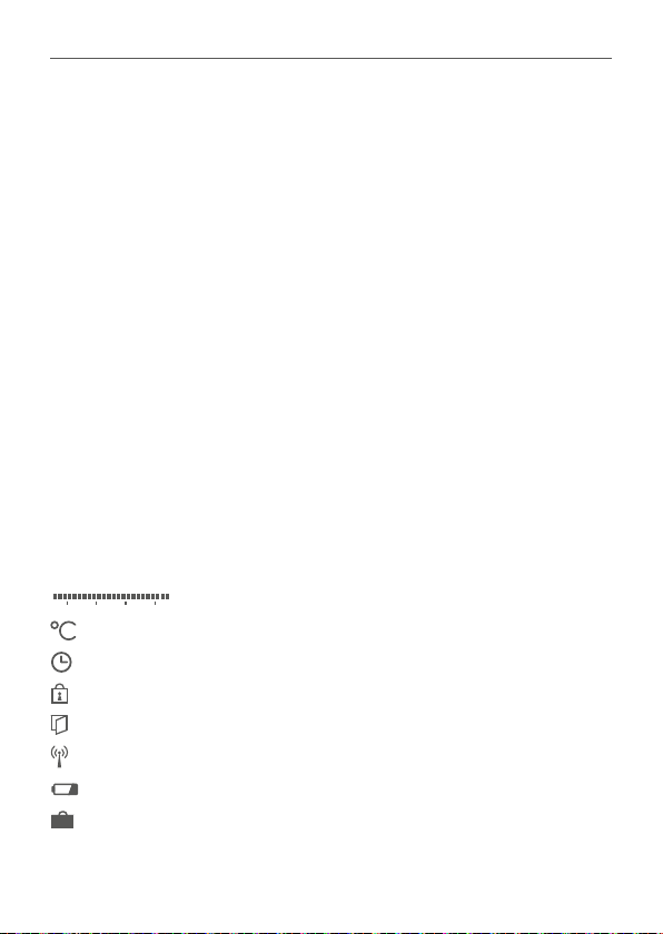
Displayübersicht Heizkörperthermostat:
Übersicht der Heizphasen
Soll-Temperatur
Uhrzeit und Datum*
Bediensperre*
Fenster-auf-Symbol
Funkübertragung
Leere Batterien
Urlaubsmodus*
Automatischer Betrieb*
Funktion und Geräteübersicht
9
Page 10

Allgemeine Systeminformationen
AUTO
MANU
BOOST
6
12
18
24
AUTO
BOOST
6
12
18
24
Offset
AUTO
MANU
BOOST
Mo Tu We Th Fr Sa Su
6
12
18
24
Prg
6
12
18
24
Mo Tu We Th Fr Sa Su
6
12
18
24
Manueller Betrieb*
Boost-Modus
Oset-Temperatur*
Programmierung eines Heizprofils*
Wochentage
* s. „6 Konfigurationsmenü des Heizkörperthermostats“ auf Seite 20
3 Allgemeine Systeminformationen
Dieses Gerät ist Teil des Homematic IP Smart-Home-Systems und
kommuniziert über das HomematicIP Funkprotokoll. Alle Geräte des
Systems können komfortabel und individuell per Smartphone über
die HomematicIP App konfiguriert werden. Alternativ haben Sie die
Möglichkeit, Homematic IP Geräte über die Zentrale CCU2/CCU3
oder in Verbindung mit vielen Partnerlösungen zu betreiben. Welcher
Funktionsumfang sich innerhalb des Systems im Zusammenspiel mit
weiteren Komponenten ergibt, entnehmen Sie bitte dem HomematicIP Anwenderhandbuch. Alle technischen Dokumente und Updates
finden Sie stets aktuell unter www.eQ-3.de.
4 Anlernen
Bitte lesen Sie diesen Abschnitt erst vollständig, bevor Sie
mit dem Anlernen beginnen.
Sie können die Geräte entweder direkt aneinander oder an den Homematic IP Access Point (HmIP-HAP) anlernen. Beim direkten Anlernen
erfolgt die Konfiguration am Gerät (z. B. über den Heizkörperthermostat) und beim Anlernen an den Access Point über die kostenlose
Homematic IP Smartphone-App.
10
Page 11
Anlernen
4.1 Direktes Anlernen
Sie können den Homematic IP Heizkörperthermostat– basic
(HmIP-eTRV-B) an den Homematic IP Fenster- und
Türkontakt mit Magnet (HmIP-SWDM) direkt anlernen.
Halten Sie beim Anlernen einen Mindestabstand von 50cm
zwischen den Geräten ein.
Sie können den Anlernvorgang durch erneute kurze Betätigung der Systemtaste (D) abbrechen. Dies wird durch rotes
Aufleuchten der Geräte-LED (D) bestätigt.
Um den Heizkörperthermostat an den Homematic IP Fenster- und
Türkontakt mit Magnet anzulernen, müssen beide Geräte in den Anlernmodus gebracht werden.
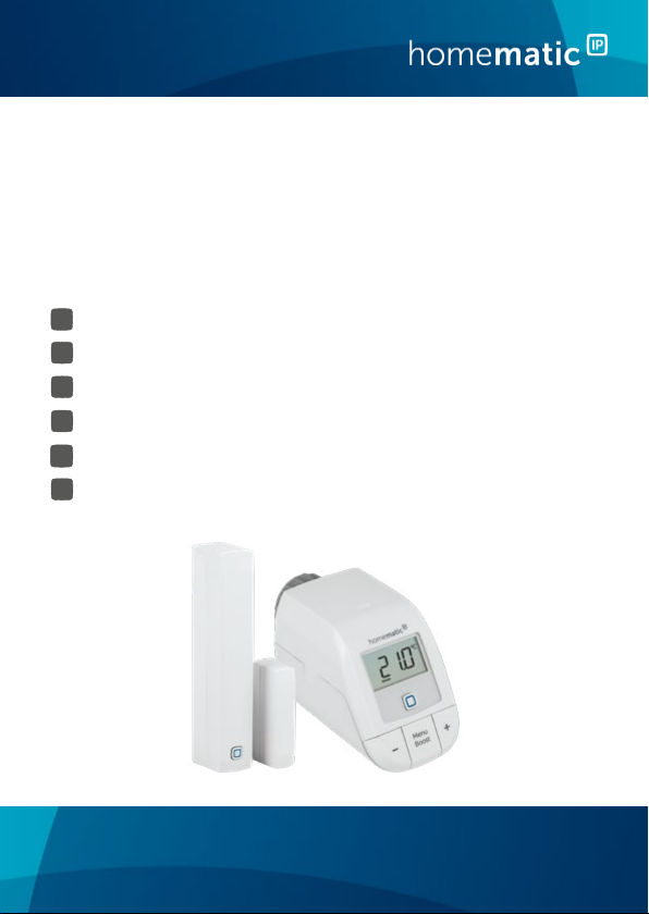
• Ziehen Sie den Isolierstreifen aus dem Batteriefach des Heizkörper-
thermostats (B) und des Fenster- und Türkontakts (M) heraus.
• Drücken Sie für mind. 4 s auf die Systemtaste des Heizkörperther-
mostats (D), um den Anlernmodus zu aktivieren (s. Abbildung 2). Die
Geräte-LED (D) beginnt orange zu blinken. Der Anlernmodus ist für
3 Minuten aktiv.
• Drücken Sie die Systemtaste des Fenster- und Türkontakts mit Ma-
gnet (L) für mind. 4 s, um den Anlernmodus zu aktivieren (s. Abbildung 2). Die Geräte-LED (L) beginnt orange zu blinken.
Erfolgreiches Anlernen wird durch grünes Blinken der Geräte-LED signalisiert. War der Anlernvorgang nicht erfolgreich, leuchtet die Geräte-LED rot auf. Versuchen Sie es erneut.
Wenn kein Anlernen erfolgt, wird der Anlernmodus automatisch nach 3 Minuten beendet.
11
Page 12
Anlernen
Wenn Sie den bestehenden Geräten ein weiteres Gerät hinzufügen möchten, müssen Sie zunächst das bereits bestehende Gerät und anschließend das neue Gerät in den Anlernmodus bringen.
Wenn Sie den bestehenden Geräten z. B. einen weiteren
Heizkörperthermostat hinzufügen möchten, müssen Sie zunächst den neuen Heizkörperthermostat an den bestehenden Heizkörperthermostat anlernen. Anschließend können
Sie den neuen Heizkörperthermostat an den bestehenden
Tür- und Fensterkontakt anlernen.
Wenn Sie mehrere Geräte in einem Raum verwenden, sollten
Sie alle Geräte aneinander anlernen.
4.2 Anlernen an den Access Point (alternativ)
Sie können das Gerät an den Homematic IP Access Point
oder an die Zentrale CCU2/CCU3 anlernen. Weitere Informationen dazu entnehmen Sie bitte dem Homematic IP Anwenderhandbuch (zu finden im Downloadbereich unter
www.eQ-3.de).
Damit das Gerät in Ihr System integriert werden und per HomematicIP App gesteuert werden kann, muss es an den Homematic IP Access Point angelernt werden.
• Önen Sie die Homematic IP App auf Ihrem Smartphone.
• Wählen Sie den Menüpunkt „Gerät anlernen“ aus.
• Ziehen Sie den Isolierstreifen aus dem Batteriefach (B bzw. M) des
Geräts heraus. Der Anlernmodus ist für 3 Minuten aktiv.
12
Page 13

Montage
Sie können den Anlernmodus manuell für weitere 3 Minuten
starten, indem Sie die Systemtaste (D bzw. L) kurz drücken.
• Das Gerät erscheint automatisch in der App.
• Zur Bestätigung geben Sie in der App die letzten vier Ziern der
Gerätenummer (SGTIN) ein oder scannen Sie den QR-Code. Die
Gerätenummer finden Sie auf dem Aufkleber im Lieferumfang oder
direkt am Gerät.
• Warten Sie, bis der Anlernvorgang abgeschlossen ist.
• Zur Bestätigung eines erfolgreichen Anlernvorgangs leuchtet die
LED grün. Das Gerät ist nun einsatzbereit. Leuchtet die LED rot, versuchen Sie es erneut.
• Wählen Sie aus, in welcher Anwendung (z. B. Raumklima) Sie das
Gerät verwenden möchten.
• Vergeben Sie in der App einen Namen für das Gerät und ordnen Sie
es einem Raum zu.
5 Montage
5.1 Montage des Heizkörperthermostats
Die Montage des Heizkörperthermostat kann ohne Ablassen von Heizungswasser oder Eingri in das Heizungssystem erfolgen. Spezialwerkzeug oder ein Abschalten der Heizung sind nicht erforderlich.
Die am Heizkörperthermostat angebrachte Überwurfmutter (A) ist universell einsetzbar und ohne Zubehör passend für alle Ventile mit dem
Gewindemaß M30 x 1,5mm der gängigsten Hersteller (z. B. Heimeier,
MNG, Junkers, Landis&Gyr (Duodyr), Honeywell-Braukmann, Oventrop, Schlösser, Comap, Valf Sanayii, R.B.M, Jaga, Siemens und Idmar).
13
Page 14
Montage
Durch den im Lieferumfang enthaltenen Adapter ist das Gerät auch
auf Heizkörperventile vom Typ Danfoss RA montierbar (s. „5.1.2 Adapter für Danfoss RA“ auf Seite 15).
5.1.1 Heizkörperthermostat montieren
Bei erkennbaren Schäden am vorhandenen Thermostat, am
Ventil oder an den Heizungsrohren wenden Sie sich bitte an
einen Fachmann.
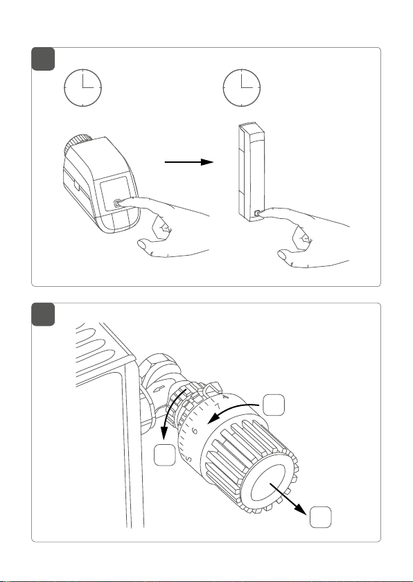
Demontieren Sie den alten Thermostatkopf von Ihrem Heizkörperventil (s. Abbildung 3).
• Drehen Sie den Thermostatkopf auf den Maximalwert (N) gegen
den Uhrzeigersinn. Der Thermostatkopf drückt jetzt nicht mehr
auf die Ventilspindel und kann so leichter demontiert werden.
Die Fixierung des Thermostatkopfes kann unterschiedlich ausgeführt
sein:
• Überwurfmutter: Schrauben Sie die Überwurfmutter gegen den
Uhrzeigersinn ab (O). Danach können Sie den Thermostatkopf
abnehmen (P).
• Schnappbefestigungen: Sie können so befestigte Thermostat-
köpfe einfach lösen, indem Sie den Verschluss/Überwurfmutter
ein klein wenig gegen den Uhrzeigersinn drehen (O). Danach können Sie den Thermostatkopf abnehmen (P).
• Klemmverschraubungen: Der Thermostatkopf wird durch einen
Befestigungsring gehalten, der mit einer Schraube zusammengehalten wird. Lösen Sie diese Schraube und nehmen Sie den Thermostatkopf vom Ventil ab (P).
• Verschraubung mit Madenschrauben: Lösen Sie die Madenschrau-
14
Page 15
Montage
be und nehmen Sie den Thermostatkopf ab (P).
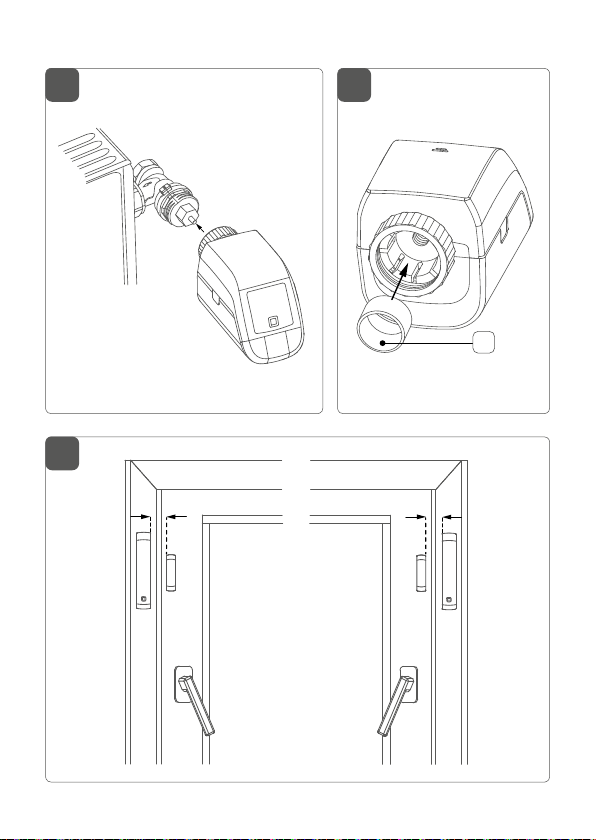
Nach der Demontage des alten Thermostatkopfes können Sie den
Homematic IP Heizkörperthermostat mit der Überwurfmutter (A) auf
das Heizkörperventil aufsetzen (s. Abbildung 4).
Bei Bedarf verwenden Sie den beiliegenden Adapter für Danfoss RAVentile (s. „5.1.2 Adapter für Danfoss RA“ auf Seite 15) oder den
beiliegenden Stützring (s. „5.1.3 Stützring“ auf Seite 16).
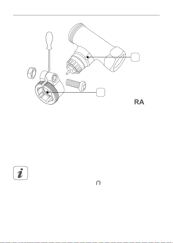
5.1.2 Adapter für Danfoss RA
Zur Montage auf RA-Ventile von Danfoss ist der beiliegende Adapter
erforderlich. Verwenden Sie ggf. einen Schraubendreher, um den Adapter leicht aufzubiegen (s. nachfolgende Abbildung).
Die Ventilkörper von Danfoss weisen umlaufend längliche Einkerbungen (1) auf, die einen besseren Sitz des Adapters nach dem Aufrasten
gewährleisten.
Achten Sie bei der Montage darauf, dass die Zapfen im Inneren des Adapters (2) eine deckungsgleiche Position zu den
Einkerbungen (1) am Ventil haben. Rasten Sie den zum Ventil
passenden Adapter vollständig auf.
Achten Sie darauf, sich nicht die Finger zwischen den Adapterhälften einzuklemmen!
Nach dem Aufrasten auf den Ventilkörper befestigen Sie die Adapter
mit der beiliegenden Schraube und Mutter.
15
Page 16
Montage
1
2
5.1.3 Stützring
Bei Ventilen einiger Hersteller weist der in das Gerät hineinragende
Teil des Ventils nur einen geringen Durchmesser auf, was zu einem
lockeren Sitz führt. In diesem Fall sollte der beiliegende Stützring (Q)
vor der Montage in den Flansch des Geräts eingelegt werden (s. Ab-
bildung 5).
5.2 Adaptierfahrt
Nach dem Einlegen der Batterien fährt der Motor zunächst zurück, um die Montage zu erleichtern. Währenddessen werden
„InS“ und das Aktivitätssymbol ( ) angezeigt.
Nachdem der Heizkörperthermostat erfolgreich montiert wurde,
muss im nächsten Schritt zur Anpassung ans Ventil eine Adaptierfahrt
(AdA) durchgeführt werden:
• Wenn im Display „AdA“ steht, drücken Sie die Menü-/Boost-Taste
(G), um die Adaptierfahrt zu starten.
16
Page 17
Montage
Der Heizkörperthermostat führt eine Adaptierfahrt durch. Dabei werden „AdA“ und das Aktivitätssymbol ( ) im Display angezeigt. Warten
Sie, bis die Adaptierfahrt beendet ist. Anschließend wechselt das Display
zur normalen Anzeige.
Wurde die Adaptierfahrt vor der Montage eingeleitet bzw.
wird eine Fehlermeldung (F1, F2, F3) angezeigt, drücken Sie
die Menü-/Boost-Taste (G) und der Motor fährt zurück zur
Position „InS“.
5.3 Montage des Fenster- und Türkontakts
5.3.1 Auswahl eines geeigneten Montageortes
• Wählen Sie das Fenster oder die Tür für die Montage des Fenster-
und Türkontakts aus.
• Befestigen Sie einen Teil des Fenster- und Türkontakts (Magnet-
kontakt (I) oder Elektronikeinheit (K)) auf dem beweglichen Teil
(Tür- oder Fensterflügel), das andere auf dem ortsfesten Teil (Rahmen) des Fensters bzw. der Tür (s. Abbildung 6).
• Befestigen Sie den Fenster- und Türkontakt auf der Seite des Fens-
ter-/Türgris im oberen Drittel auf dem Fenster-/Türrahmen (s.
Abbildung 6) (zur Befestigung s. „5.3.2 Klebestreifenmontage“ auf
Seite 18).
• Der Magnetkontakt kann horizontal oder vertikal und links oder
rechts von der Elektronikeinheit des Fenster- und Türkontakts
montiert werden.
Die Elektronikeinheit und der Magnetkontakt sollten sich
möglichst auf der gleichen Höhe befinden. Dafür können Sie
beim Magnetkontakt ein Distanzstück (J) einsetzen.
17
Page 18

Montage
Der ideale Abstand zwischen der Gehäusekante des Fensterund Türkontakts und des Magnetkontakts beträgt 5 mm (s.
Abbildung 6).
5.3.2 Klebestreifenmontage
Achten Sie bei der Klebestreifenmontage darauf, dass der
Montageuntergrund glatt, unbeschädigt, sauber, fett- und
lösungsmittelfrei sowie nicht zu kühl ist.
Um den Fenster- und Türkontakt mit dem Klebestreifen zu montieren,
gehen Sie wie folgt vor:
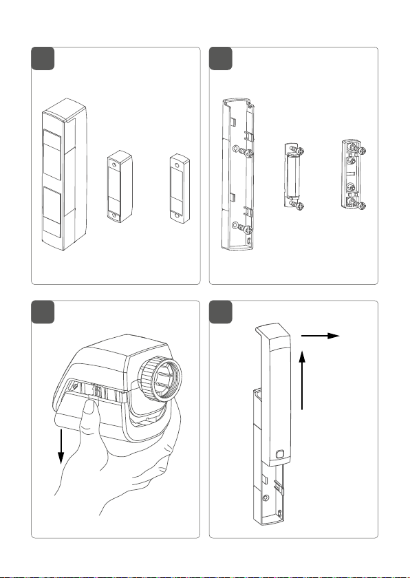
• Bringen Sie den großen doppelseitigen Klebestreifen auf der Rück-
seite der Halterung (H) an (s. Abbildung 7) und drücken Sie das Gerät an die gewünschte Position.
• Legen Sie den Magneten in die Halterung der Rückseite und set-
zen Sie die Rückseite in das Gehäuse des Magnetkontakts ein.
Bei Verwendung des Distanzstücks (J) müssen Sie den kleinen
Klebestreifen auf der Rückseite des Distanzstücks anbringen (s.
Abbildung 7) und dieses an die gewünschte Position am Fenster
drücken. Setzen Sie anschließend den Magnetkontakt auf das
Distanzstück auf.
• Bringen Sie den kleinen doppelseitigen Klebestreifen auf der
Rückseite des Magnetkontakts (I) an (s. Abbildung 7) und drücken
Sie den Magnetkontakt an die gewünschte Position am Fenster.
18
Page 19
Montage
5.3.3 Schraubmontage
Setzen Sie den Magnetkontakt vor der Schraubmontage
noch nicht zusammen.
Für die Schraubmontage, gehen Sie wie folgt vor:
• Bohren Sie die Schraublöcher in der Halterung(H) mit einem ge-
eigneten Bohrer vor.
• Markieren Sie die Schraublöcher für die Elektronikeinheit (K) an-
hand der Halterung auf dem Fenster.
• Markieren Sie die Schraublöcher für den Magnetkontakt (I) bzw.
bei Bedarf für das Distanzstück (J) auf dem Fenster.
• Bohren Sie bei Befestigung auf harten Untergründen mit einem
1,5 mm Bohrer vor.
• Halten Sie die Halterung der Elektronikeinheit an die gewünsch-
te Montagestelle und drehen Sie beide Schrauben (2,2 x 16 mm)
durch die Schraublöcher ein (s. Abbildung 8).
• Setzen Sie die Elektronikeinheit in die Halterung ein.
• Halten Sie die Rückseite des Magnetkontakts bzw. das Distanz-
stück an die gewünschte Montagestelle und drehen Sie beide
Schrauben (2,2 x 13 mm) durch die Schraublöcher ein (s. Abbil-
dung 8).
• Legen Sie den Magneten in die Halterung und setzen Sie die Rück-
seite in das Gehäuse des Magnetkontakts ein.
Bei Verwendung des Distanzstücks können Sie den Magnetkontakt nach der Montage einfach auf das Distanzstück aufsetzen.
19
Page 20
Konfigurationsmenü des Heizkörperthermostats
AUTO
6
12
18
24
AUTO
MANU
BOOST
6
12
18
24
Offset
AUTO
MANU
BOOST
Mo Tu We Th Fr Sa Su
6
12
18
24
Prg
6
12
18
24
24
18
24
18
24
6 Konfigurationsmenü des Heizkörperthermostats
Wenn Sie den Heizkörperthermostat ohne Homematic IP Access
Point betreiben, können Sie nach der Inbetriebnahme direkt am Gerät
über das Konfigurationsmenü folgende Modi auswählen und Einstellungen vornehmen, um das Gerät an Ihre persönlichen Bedürfnissen
anzupassen.
• Durch langes Drücken (mind. 2 s) der Menü-Taste (G) gelangen Sie
ins Konfigurationsmenü.
• Wählen Sie das gewünschte Symbol über die Plus- oder Minus-
Taste (E und F) und kurzes Drücken der Menü-Taste aus, um Einstellungen für die verschiedenen Menüpunkte vorzunehmen.
Durch langes Drücken der Menü-Taste gelangen Sie zur vorherigen
Ebene zurück. Wenn für mehr als 1 Minute keine Betätigung am Gerät
erfolgt, schließt sich das Menü automatisch, ohne eingestellte Änderungen zu übernehmen.
6.1
6.2
6.7
6.5
6.4
6.6
6.3
20
Automatikbetrieb
Manueller Betrieb
Oset-Temperatur
Programmierung eines Heizprofils
Bediensperre
Datum und Uhrzeit
Urlaubsmodus
Wenn Sie das Gerät an den Access Point anlernen, können
Sie die Einstellungen bequem über die Homematic IP App
vornehmen.
Page 21

Konfigurationsmenü des Heizkörperthermostats
Falls Sie bereits Einstellungen im Konfigurationsmenü vorgenommen oder das Gerät bereits direkt an ein anderes Homematic IP Gerät angelernt haben, müssen Sie zum Anlernen
des Heizkörperthermostats an einen Homematic IP Access
Point oder an eine Zentrale CCU2/CCU3 zunächst die
Werkseinstellungen des Geräts wiederherstellen (s. „10 Wiederherstellung der Werkseinstellungen“ auf Seite 30).
6.1 Automatischer Betrieb
Im Automatikbetrieb erfolgt die Temperaturregelung gemäß dem eingestellten Heizprofil. Manuelle Änderungen bleiben bis zum nächsten
Schaltzeitpunkt aktiv. Danach wird das eingestellte Heizprofil wieder
aktiviert. Um den automatischen Betrieb zu aktivieren, gehen Sie wie
folgt vor:
• Wählen Sie über die Plus- oder Minus-Tasten (E und F) den Menü-
punkt „Auto“ aus.
• Bestätigen Sie mit der Menü-Taste.
Zur Bestätigung blinkt das Symbol zweimal kurz auf und das Gerät
wechselt in den automatischen Betrieb.
6.2 Manueller Betrieb
Im manuellen Betrieb erfolgt die Temperaturregelung gemäß der über
die Tasten (E und F) eingestellten Temperatur. Die Temperatur bleibt bis
zur nächsten manuellen Änderung erhalten. Um den manuellen Betrieb
zu aktvieren, gehen Sie wie folgt vor:
• Wählen Sie über die Plus- oder Minus-Taste (E und F) den Menü-
punkt „Manu“ aus.
• Bestätigen Sie mit der Menü-Taste.
21
Page 22

Konfigurationsmenü des Heizkörperthermostats
Zur Bestätigung blinkt das Symbol zweimal kurz auf und das Gerät
wechselt in den manuellen Betrieb.
6.3 Oset-Temperatur
Da die Temperatur am Heizkörperthermostaten gemessen wird, kann
es an einer anderen Stelle im Raum kälter oder wärmer sein. Um dies
anzugleichen, kann eine Oset-Temperatur von ±3.5 °C eingestellt
werden. Werden z. B. 18 °C anstatt eingestellter 20 °C gemessen, ist
ein Oset von -2.0 °C einzustellen. Werksseitig ist eine Oset-Temperatur von 0.0 °C eingestellt. Um die Oset-Temperatur individuell
anzupassen, gehen Sie wie folgt vor:
• Wählen Sie über die Plus- oder Minus-Tasten (E und F) den Menü-
punkt „Oset“ aus.
• Bestätigen Sie mit der Menü-Taste.
• Wählen Sie über die Plus- oder Minus-Tasten die gewünschte O-
set-Temperatur aus und bestätigen Sie mit der Menü-Taste.
Zur Bestätigung blinkt die Temperatur zweimal kurz auf und das Gerät
wechselt zurück zur Standardanzeige.
6.4 Programmierung eines Heizprofils
Unter diesem Menüpunkt können Sie ein Heizprofil mit sechs Heizund Absenkphasen (13 Schaltzeitpunkte) nach Ihren eigenen Bedürfnissen erstellen.
• Wählen Sie über die Plus- oder Minus-Tasten (E und F) den Menü-
punkt „Prg“ aus und bestätigen Sie mit der Menü-Taste.
• Wählen Sie unter „dAY“ über die Plus- oder Minus-Tasten einzelne
Wochentage, alle Werktage, das Wochenende oder die gesamte
Woche für Ihr Heizprofil aus und bestätigen Sie mit der Menü-
22
Page 23

Konfigurationsmenü des Heizkörperthermostats
Taste.
• Bestätigen Sie die Startzeit 00:00 Uhr mit der Menü-Taste.
• Wählen Sie über die Plus- oder Minus-Tasten die gewünschte
Temperatur für die Startzeit aus und bestätigen Sie mit der MenüTaste.
• Im Display wird die nächste Uhrzeit angezeigt. Sie können diese
Zeit über die Plus- oder Minus-Tasten verändern.
• Wählen Sie über die Plus- oder Minus-Tasten die gewünschte
Temperatur für den nächsten Zeitabschnitt aus und bestätigen Sie
mit der Menü-Taste.
• Wiederholen Sie diesen Vorgang, bis für den gesamten Zeitraum
von 0:00 bis 23:59 Uhr Temperaturen hinterlegt sind.
Zur Bestätigung blinkt die Uhrzeit zweimal kurz auf und das Gerät
wechselt zurück zur Standardanzeige.
6.5 Bediensperre
Die Bedienung am Gerät kann gesperrt werden, um das ungewollte
Verändern von Einstellungen, z. B. durch versehentliches Berühren,
zu verhindern. Um die Bediensperre zu aktivieren bzw. deaktivieren,
gehen Sie wie folgt vor:
• Wählen Sie über die Plus- oder Minus-Tasten (E und F) den Menü-
punkt „24“ aus.
• Bestätigen Sie mit der Menü-Taste.
• Wählen Sie über die Plus- oder Minus-Tasten „On“, um die Bedien-
sperre zu aktivieren oder „OFF“, um die Bediensperre zu deaktivieren und bestätigen Sie mit der Menü-Taste.
Zur Bestätigung blinkt die Auswahl zweimal kurz auf und das Gerät
23
Page 24

Konfigurationsmenü des Heizkörperthermostats
18
24
wechselt zurück zur Standardanzeige.
Bei Aktivierung der Bediensperre wird das Symbol „Schloss“ im Display
angezeigt.
Um die Bediensperre zu deaktivieren, gehen Sie wie folgt vor:
• Drücken Sie für ca. 2 s auf die Menü-Taste (G), um das Konfigura-
tionsmenü zu önen.
• Bestätigen Sie mit der Menü-Taste.
• Wählen Sie über die Plus- oder Minus-Tasten (E und F) „OFF“ aus,
um die Bediensperre zu deaktivieren.
6.6 Uhrzeit und Datum
Um Datum und Uhrzeit einzustellen, gehen Sie wie folgt vor:
• Wählen Sie über die Plus- oder Minus-Tasten (E und F) den Menü-
punkt „
• Bestätigen Sie mit der Menü-Taste.
• Wählen Sie über die Plus- oder Minus-Tasten das Jahr aus und
bestätigen Sie mit der Menü-Taste.
• Wählen Sie über die Plus- oder Minus-Tasten den Monat aus und
bestätigen Sie mit der Menü-Taste.
• Wählen Sie über die Plus- oder Minus-Tasten den Tag aus und be-
stätigen Sie mit der Menü-Taste.
• Wählen Sie über die Plus- oder Minus-Tasten die Stunden aus und
bestätigen Sie mit der Menü-Taste.
• Wählen Sie über die Plus- oder Minus-Tasten die Minuten aus und
bestätigen Sie mit der Menü-Taste.
“ aus.
Zur Bestätigung blinkt die Uhrzeit zweimal kurz auf und das Gerät
wechselt zurück zur Standardanzeige.
24
Page 25

Bedienung des Heizkörperthermostats
18
24
6.7 Urlaubsmodus
Der Urlaubsmodus kann genutzt werden, wenn für einen bestimmten
Zeitraum dauerhaft eine feste Temperatur gehalten werden soll (z. B.
während eines Urlaubs oder einer Party). Um den Urlaubsmodus einzustellen, gehen Sie wie folgt vor:
• Wählen Sie über die Plus- oder Minus-Tasten (E und F) den Menü-
punkt „
“ aus und bestätigen Sie mit der Menü-Taste.
• Geben Sie über die Plus- oder Minus-Tasten die Uhrzeit ein, bis
zu der der Urlaubsmodus aktiv sein soll und bestätigen Sie mit der
Menü-Taste.
• Geben Sie über die Plus- oder Minus-Tasten das Datum ein, bis zu
dem der Urlaubsmodus aktiv sein soll und bestätigen Sie mit der
Menü-Taste.
• Geben Sie über die Plus- oder Minus-Tasten die gewünschte Tem-
peratur für die Zeit der Abwesenheit ein und bestätigen Sie mit der
Menü-Taste.
Zur Bestätigung blinkt das Symbol zweimal kurz auf und das Gerät
wechselt in den Urlaubsmodus.
7 Bedienung des Heizkörperthermostats
Nach dem Anlernen und der Montage stehen Ihnen einfache Bedienfunktionen direkt am Gerät zur Verfügung.
• Temperatur: Drücken Sie die linke (E) oder rechte (F) Taste, um die
Temperatur des Heizkörpers manuell zu verändern. Im Automatikbetrieb bleibt die manuell eingestellte Temperatur bis zum nächsten Schaltzeitpunkt bestehen. Danach wird das eingestellte Heizprofil wieder aktiviert. Im manuellen Betrieb bleibt die Temperatur
bis zur nächsten manuellen Änderung erhalten.
25
Page 26
Batterien wechseln
• Boost-Funktion: Drücken Sie die Boost-Taste (G) kurz, um die
Boost-Funktion für schnelles, kurzzeitiges Aufheizen des Heizkörpers durch Önung des Ventils zu aktivieren. Dadurch wird sofort
ein angenehmes Wärmegefühl im Raum erreicht.
8 Batterien wechseln
Wird eine leere Batterie in der App bzw. am Gerät angezeigt, tauschen
Sie die verbrauchten Batterien gegen neue Batterien aus. Beachten Sie
dabei den Batterietyp und die richtige Polung der Batterien.
• Önen Sie das Batteriefach (B bzw. M) des Geräts (s. Abbildung 9
bzw. 10).
• Entnehmen Sie die leeren Batterien.
• Legen Sie die neuen Batterien entsprechend den Polaritätsmar-
kierungen in das Batteriefach ein.
Verwenden Sie beim Heizkörperthermostat zwei 1,5 V LR6/
Mignon/AA Batterien und beim Tür- und Fensterkontakt zwei
1,5 V LR03/Micro/AAA Batterien.
• Schließen Sie das Batteriefach wieder.
• Achten Sie nach dem Einlegen der Batterien auf die Blinkfolgen
der LED (s. „9.3 Fehlercodes und Blinkfolgen“ auf Seite 28).
Nach dem Einlegen der Batterien führt der Heizkörperthermostat zunächst für ca. 2 Sekunden einen Selbsttest durch. Danach erfolgt die
Initialisierung. Den Abschluss bildet die Test-Anzeige: oranges und
grünes Leuchten.
26
Page 27
Fehlerbehebung
Vorsicht! Explosionsgefahr bei unsachgemäßem Austausch
der Batterien. Ersatz nur durch denselben oder einen gleichwertigen Typ. Batterien dürfen niemals aufgeladen werden.
Batterien nicht ins Feuer werfen. Batterien nicht übermäßiger
Wärme aussetzen. Batterien nicht kurzschließen. Es besteht
Explosionsgefahr!
Verbrauchte Batterien gehören nicht in den Hausmüll! Entsorgen Sie diese in Ihrer örtlichen Batteriesammelstelle!
9 Fehlerbehebung
9.1 Befehl nicht bestätigt
Bestätigt mindestens ein Empfänger einen Befehl nicht, leuchtet zum Abschluss der fehlerhaften Übertragung die LED (D
bzw. L) rot auf. Grund für die fehlerhafte Übertragung kann
eine Funkstörung sein (s. „12 Allgemeine Hinweise zum
Funkbetrieb“ auf Seite 31). Die fehlerhafte Übertragung kann folgende Ursachen haben:
• Empfänger nicht erreichbar,
• Empfänger kann Befehl nicht ausführen (Lastausfall, mechanische
Blockade etc.) oder
• Empfänger defekt.
9.2 Duty Cycle
Der Duty Cycle beschreibt eine gesetzlich geregelte Begrenzung der
Sendezeit von Geräten im 868 MHz-Bereich. Das Ziel dieser Regelung
ist es, die Funktion aller im 868 MHz-Bereich arbeitenden Geräte zu
gewährleisten. In dem von uns genutzten Frequenzbereich 868 MHz
27
Page 28

Fehlerbehebung
beträgt die maximale Sendezeit eines jeden Geräts 1 % einer Stunde
(also 36 Sekunden in einer Stunde). Die Geräte dürfen bei Erreichen
des 1 %-Limits nicht mehr senden, bis diese zeitliche Begrenzung vorüber ist. Gemäß dieser Richtlinie, werden Homematic IP Geräte zu
100% normenkonform entwickelt und produziert. Im normalen Betrieb wird der Duty Cycle in der Regel nicht erreicht. Dies kann jedoch
in Einzelfällen bei der Inbetriebnahme oder Erstinstallation eines Systems durch vermehrte und funkintensive Anlernprozesse der Fall sein.
Eine Überschreitung des Duty Cycle-Limits wird durch einmal langes
rotes Leuchten der Geräte-LED (D bzw. L) angezeigt und kann sich
durch temporär fehlende Funktion des Geräts äußern. Nach kurzer
Zeit (max. 1 Stunde) ist die Funktion des Geräts wiederhergestellt.
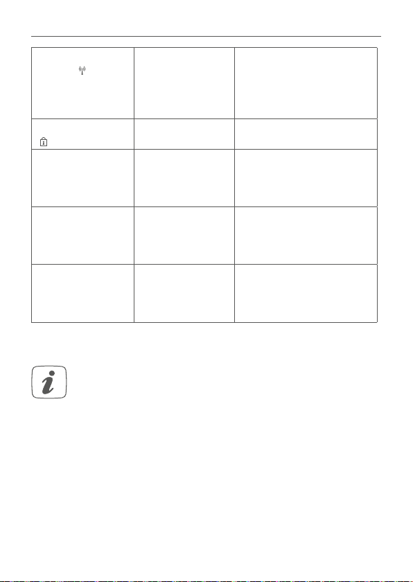
9.3 Fehlercodes und Blinkfolgen
Blinkcode/
Displayanzeige
Kurzes oranges
Blinken
1x langes grünes
Leuchten
1x langes rotes
Leuchten
Bedeutung Lösung
Funkübertragung/Sendever-
Warten Sie, bis die Über-
tragung beendet ist.
such/Datenübertragung
Vorgang bestätigt Sie können mit der Bedie-
nung fortfahren.
Vorgang fehlge-
schlagen oder
Duty Cycle-Limit
erreicht
Versuchen Sie es erneut
(s. „9.1 Befehl nicht
bestätigt“ auf Seite 27
oder „9.2 Duty Cycle“ auf
Seite 27).
28
Page 29

Fehlerbehebung
Kurzes oranges
Blinken
Anlernmodus
aktiv
(alle 10 s)
Schnelles oranges Blinken
Direkter Anlernmodus aktiv
F1 Ventilantrieb
schwergängig
F2 Stellbereich zu
groß
F3 Stellbereich zu
klein
Batteriesymbol
)
(
Batteriesymbol (
) und ---
Batteriespannung
gering
Ventilnotposition
wurde angefahren
Kurzes oranges
Batterien leer Tauschen Sie die Batte-
Leuchten (nach
grüner oder roter
Empfangsmeldung)
Geben Sie die letzten vier
Ziern der Geräte-Serien-
nummer zur Bestätigung
ein (s. „4.2 Anlernen an den
Access Point (alternativ)“
auf Seite 12).
Aktivieren Sie den An-
lernmodus des anzuler-
nenden Geräts (s. „4.1
Direktes Anlernen“ auf
Seite 11).
Prüfen Sie, ob der Stößel
des Heizungsventils
klemmt.
Überprüfen Sie die Befes-
tigung des Heizkörper-
thermostats
Prüfen Sie, ob der Stößel
des Heizungsventils
klemmt.
Tauschen Sie die Batte-
rien des Geräts aus (s. „8
Batterien wechseln“ auf
Seite 26).
Tauschen Sie die Batte-
rien des Geräts aus (s. „8
Batterien wechseln“ auf Seite
26).
rien des Geräts aus (s. „8
Batterien wechseln“ auf
Seite 26).
29
Page 30
Wiederherstellung der Werkseinstellungen
24
Antennensymbol (24) blinkt
Kommunikationsstörung zum
Access Point
oder zum ange-
Prüfen Sie die Verbin-
dung zum Access Point
bzw. zu den angelernten
Geräten.
lernten Gerät
Schlosssymbol
)
(
6x langes rotes
Blinken
Bediensperre
aktiv
Gerät defekt Achten Sie auf die An-
Deaktivieren Sie die Be-
diensperre in der App.
zeige in Ihrer App und
wenden Sie sich an Ihren
Fachhändler.
1x oranges und 1x
grünes Leuchten
(nach dem Einle-
Testanzeige Nachdem die Testanzeige
erloschen ist, können Sie
fortfahren.
gen der Batterien)
Langes und
kurzes oranges Blinken (im
Aktualisierung der
Geräte-software
(OTAU)
Warten Sie, bis das
Update beendet ist.
Wechsel)
10 Wiederherstellung der Werkseinstellungen
Die Werkseinstellungen des Geräts können wiederhergestellt
werden. Dabei gehen alle Einstellungen verloren.
Um die Werkseinstellungen des Geräts wiederherzustellen, gehen Sie
wie folgt vor:
• Önen Sie das Batteriefach (B bzw. M) des Geräts (s. Abbildung 9
bzw. 10) und entnehmen Sie eine Batterie.
• Legen Sie die Batterie entsprechend den Polaritätsmarkierungen
wieder ein und halten Sie gleichzeitig die Systemtaste (D bzw. L)
für 4 s gedrückt, bis die LED schnell orange zu blinken beginnt (s.
Abbildung 2).
30
Page 31

Wartung und Reinigung
• Lassen Sie die Systemtaste wieder los.
• Drücken Sie die Systemtaste erneut für 4 s, bis die Geräte-LED (D
bzw. L) grün aufleuchtet.
• Lassen Sie die Systemtaste wieder los, um das Wiederherstellen
der Werkseinstellungen abzuschließen. Das Gerät führt einen
Neustart durch.
11 Wartung und Reinigung
Das Gerät ist für Sie bis auf einen Batteriewechsel wartungsfrei.
Überlassen Sie eine Reparatur einer Fachkraft.
Reinigen Sie das Gerät mit einem weichen, sauberen, trockenen und
fusselfreien Tuch. Verwenden Sie keine lösemittelhaltigen Reinigungsmittel, das Kunststogehäuse und die Beschriftung können dadurch
angegrien werden.
12 Allgemeine Hinweise zum Funkbetrieb
Die Funk-Übertragung wird auf einem nicht exklusiven Übertragungsweg realisiert, weshalb Störungen nicht ausgeschlossen werden
können. Weitere Störeinflüsse können hervorgerufen werden durch
Schaltvorgänge, Elektromotoren oder defekte Elektrogeräte.
Die Reichweite in Gebäuden kann stark von der im Freifeld
abweichen. Außer der Sendeleistung und den Empfangseigenschaften der Empfänger spielen Umwelteinflüsse wie
Luftfeuchtigkeit neben baulichen Gegebenheiten vor Ort
eine wichtige Rolle.
31
Page 32

Technische Daten
Hiermit erklärt die eQ-3 AG, Maiburger Str. 29, 26789 Leer, Deutschland, dass der Funkanlagentyp Homematic IP HmIP-eTRV-B und
HmIP-SWDM der Richtlinie 2014/53/EU entspricht. Der vollständige
Text der EU-Konformitätserklärung ist unter der folgenden Internetadresse verfügbar: www.eq-3.de
13 Technische Daten
Funk-Frequenzband: 868,0-868,6 MHz
869,4-869,65 MHz
Max. Funk-Sendeleistung: 10 dBm
Empfängerkategorie: SRD category 2
Duty Cycle: < 1 % pro h/< 10 % pro h
Schutzart: IP20
Heizkörperthermostat
Geräte-Kurzbezeichnung:
Versorgungsspannung: 2x 1,5 V LR6/Mignon/AA
Stromaufnahme: 100 mA max.
Batterielebensdauer: 2 Jahre (typ.)
Umgebungstemperatur: 0 bis 50 °C
Wirkungsweise: Typ 1
Verschmutzungsgrad: 2
Abmessungen (B x H x T): 57 x 68 x 102 mm
Gewicht: 185 g (inkl. Batterien)
Typ. Funk-Freifeldreichweite: 250 m
Anschluss: M30 x 1,5 mm
Stellkraft: > 80 N
Ventil-Hub: 4,3 ± 0,3 mm
HmIP-eTRV-B
32
Page 33

Technische Daten
Fenster- und Türkontakt
Geräte-Kurzbezeichnung:
HmIP-SWDM
Versorgungsspannung: 2x 1,5 V LR03/Micro/AAA
Stromaufnahme: 35 mA max.
Batterielebensdauer: 4 Jahre (typ.)
Umgebungstemperatur: -10 bis +50 °C
Abmessungen
Elektronikeinheit (B x H x T): 102 x 18 x 25 mm
Abmessungen
Magnetkontakt (B x H x T): 48 x 11 x 13 mm
Gewicht Elektronikeinheit: 46 g (inkl. Batterien)
Gewicht Magnetkontakt: 17 g (inkl. Magnet)
Typ. Funk-Freifeldreichweite: 200 m
Technische Änderungen vorbehalten.
Entsorgungshinweis
Gerät nicht im Hausmüll entsorgen! Elektronische Geräte
sind entsprechend der Richtlinie über Elektro- und Elektronik-Altgeräte über die örtlichen Sammelstellen für Elektronik-Altgeräte zu entsorgen.
Konformitätshinweis
Das CE-Zeichen ist ein Freiverkehrszeichen, das sich ausschließlich an die Behörden wendet und keine Zusicherung
von Eigenschaften beinhaltet.
Bei technischen Fragen zum Gerät wenden Sie sich bitte an
Ihren Fachhändler.
33
Page 34

EN
Package contents
Quantity Description
1 Homematic IP Radiator Thermostat – compact
1 Homematic IP Window / Door Contact with magnet
2 1.5 V LR6/mignon/AA batteries
2 1.5 V LR03/micro/AAA batteries
1 Danfoss RA adapter
10 Mounting accessories
1 User manual
1 Safety instructions
Documentation © 2018 eQ-3 AG, Germany
All rights reserved. Translation from the original version in German. This
manual may not be reproduced in any format, either in whole or in part, nor
may it be duplicated or edited by electronic, mechanical or chemical means,
without the written consent of the publisher.
Typographical and printing errors cannot be excluded. However, the information contained in this manual is reviewed on a regular basis and any necessary
corrections will be implemented in the next edition. We accept no liability for
technical or typographical errors or the consequences thereof.
All trademarks and industrial property rights are acknowledged.
Printed in Hong Kong
Changes may be made without prior notice as a result of technical advances.
150051
Version 1.0 (07/2018)
34
Page 35

Table of contents
1 Information about this manual ....................................................36
2 Function and device overview .....................................................36
3 General system information .........................................................38
4 Teaching-in ......................................................................................38
4.1 Direct pairing .....................................................................39
4.2 Teaching-in to the Access Point (alternative) .............40
5 Installation ........................................................................................ 41
5.1 Installation of the radiator thermostat ......................... 41
5.2 Adaption run ......................................................................44
5.3 Mounting the window / door contact .......................... 44
6 Configuration menu of the radiator thermostat ......................47
6.1 Automatic operation ........................................................48
6.2 Manual operation ..............................................................49
6.3 Oset temperature ...........................................................49
6.4 Programming a heating profile ......................................50
6.5 Operating lock ...................................................................50
6.6 Time and date .................................................................... 51
6.7 Holiday mode .................................................................... 52
7 Operation of the radiator thermostat ......................................... 52
8 Replacing batteries .........................................................................53
9 Troubleshooting .............................................................................. 54
9.1 Command not confirmed ...............................................54
9.2 Duty cycle .......................................................................... 54
9.3 Error codes and flashing sequences ............................. 55
10 Restore factory settings ................................................................. 57
11 Maintenance and cleaning ............................................................58
12 General information about radio operation .............................. 58
13 Technical specifications .................................................................59
35
Page 36

Information about this manual
1 Information about this manual
Please read this manual carefully before beginning operation with
your Homematic IP components. Keep the manual so you can refer
to it at a later date if you need to. If you hand over the device to other
persons for use, please hand over this manual as well.
Symbols used:
Attention!
This indicates a hazard.
Please note: This section contains important additional
information.
2 Function and device overview
The Homematic IP Radiator Thermostat oers time-controlled and
demand-based regulation of the room temperature via a heating
profile with individual heating phases. The Homematic IP Window /
Door Contact reliably detects open windows and doors by an integrated magnet sensor. This automatically reduces the room temperature when windows are open.
You can directly configure the radiator thermostat on the device and
adjust the heating profiles to your personal needs.
Alternatively, you can use the devices in conjunction with a
HomematicIP Access Point and integrate them comfortably into the
Homematic IP smart home system via the free smartphone app and
use it with comprehensive climate control and security applications.
36
Page 37

Device overview radiator thermostat (see figure 1):
0
6
12
18
24
24
18
24
24
24
24
18
24
AUTO
6
12
18
24
(A) Union nut
(B) Battery compartment
(C) Display
(D) System button (teach-in button and LED)
(E) Minus button
(F) Plus button
(G) Menu/Boost button
Device overview window and door contact (see figure 1):
(H) Bracket
(I) Magnet contact
(J) Spacer (6 mm) for magnetic contact
(K) Electronic unit
(L) System button (teach-in/pairing button and LED)
(M) Battery compartment
Display overview radiator thermostat:
Overview of heating phases
Setpoint temperature
Time and date*
Operating lock*
Open window symbol
Radio transmission
Empty batteries
Holiday mode*
Automatic operation*
Function and device overview
37
Page 38

General system information
AUTO
MANU
BOOST
6
12
18
24
AUTO
BOOST
6
12
18
24
Offset
AUTO
MANU
BOOST
Mo Tu We Th Fr Sa Su
6
12
18
24
Prg
6
12
18
24
Mo Tu We Th Fr Sa Su
6
12
18
24
Manual operation*
Boost mode
Oset temperature*
Programming a heating profile*
Days of the week
* see „6 Configuration menu of the radiator thermostat“ on page 47
3 General system information
This device is part of the HomematicIP smart home system and works
with the Homematic IP radio protocol. All devices of the system can
be configured comfortably and individually with the Homematic IP
smartphone app. Alternatively, you can operate the Homematic IP
devices via the Central Control Unit CCU2/CCU3 or in connection
with various partner solutions. The available functions provided by
the system in combination with other components are described in
the Homematic IP User Guide. All current technical documents and
updates are provided at www.eQ-3.com.
4 Teaching-in
Please read this entire section before starting the teach-in
procedure.
You can either pair the devices directly with each other or via the
Homematic IP Access Point (HmIP-HAP). After pairing, configuration
has to be done directly on the device (e.g. via the radiator thermostat)
and after teaching-in to the Access Point, configuration is done via
the free Homematic IP smartphone app.
38
Page 39

Teaching-in
4.1 Direct pairing
You can directly pair the Homematic IP Radiator Thermostat
– basic (HmIP-eTRV-B) to the Homematic IP Window /
Door Contact with magnet (HmIP-SWDM).
Please make sure you maintain a distance of at least 50cm
between the devices.
You can cancel the pairing procedure by briefly pressing the
system button (D) again. This will be indicated by the device
LED (D) lighting up red.
To connect the radiator thermostat to the Homematic IP Window /
Door Contact with magnet, the pairing mode of both devices has to
be activated.
• Remove the insulation strip from the battery compartment of the
radiator thermostat (B) and the window / door contact (M).
• Press and hold down the system button of the radiator thermostat
(D) for at least 4 seconds to activate the pairing mode (see figure
2). The device LED (D) starts to flash orange. Pairing mode remains
activated for 3 minutes.
• Press and hold down the system button of the window / door
contact with magnet (L) for at least 4 seconds to activate the
pairing mode (see fig. 2). The device LED (L) starts to flash orange.
The device LED lights up green to indicate that teaching-in has been
successful. If teaching-in failed, the device LED lights up red. Please
try again.
39
Page 40

Teaching-in
If no pairing operations are carried out, pairing mode is
exited automatically after 3 seconds.
If you want to add another device to the existing devices,
first activate the pairing mode of the existing device and afterwards the of the new device.
If, for example, you want to add another radiator thermostat, first pair the new radiator thermostat to the existing
radiator thermostat. Afterwards, you can pair the new radiator thermostat with the existing window / door contact.
If you are using several devices in one room, you should pair
all devices with each other.
4.2 Teaching-in to the Access Point (alternative)
You can connect the devices either to the Homematic IP
Access Point or the Central Control Unit CCU2/CCU3. For
detailed information, please refer to the Homematic IP User
Guide, available for download in the download area of
www.eQ-3.com.
To integrate the device into your system and to enable control
via the Homematic IP app, you must teach-in the device to your
HomematicIP Access Point first.
• Open the Homematic IP app on your smartphone.
• Select the menu item “Teach-in device”.
• Remove the insulation strip from the battery compartment (B or
M) of the device. Teach-in mode remains activated for 3 minutes.
40
Page 41

Installation
You can manually start the teach-in mode for another 3 minutes by pressing the system button briefly (D or L) .
• Your device will automatically appear in the app.
• To confirm, please enter the last four digits of the device number
(SGTIN) in your app or scan the QR code. Therefore, please see
the sticker supplied or attached to the device.
• Please wait until teach-in is completed.
• If teaching-in was successful, the LED lights up green. The device
is now ready for use. If the LED lights up red, please try again.
• Please select, in which application (e.g. climate control) you
would like to use the device.
• In the app, give the device a name and allocate it to a room.
5 Installation
5.1 Installation of the radiator thermostat
The radiator thermostat can be installed without draining heating
water or intervening in the heating system. No special tools are required, nor does the heating have to be switched o.
The union nut (A) attached to the radiator thermostat can be used
universally and without accessories for all valves with a thread size
of M30 x 1.5 from the most popular manufacturers such as Heimeier,
MNG, Junkers, Landis&Gyr (Duodyr), Honeywell-Braukmann, Oventrop, Schlösser, Comap, Valf Sanayii, R.B.M, Jaga, Siemens or Idmar.
By means of the adapter in the delivery, the device can be installed
also on radiator valves of type Danfoss RA (see „5.1.1 Mounting the
radiator thermostat“ on page 42).
41
Page 42

Installation
5.1.1 Mounting the radiator thermostat
In case of visible damage of the existing radiator, valve or
heating pipes, please contact a specialist.
Remove the old thermostat dial from your radiator valve (see section 3).
• Rotate the thermostat dial to the maximum value (N) (anti-
clockwise). The thermostat dial then no longer presses against
the valve spigot, making it easier to remove.
There are dierent ways of fixing the position of the thermostat dial:
• Union nut: Unscrew the union nut in an anticlockwise direction
(O). The thermostat dial can then be removed (P).
• Snap-on fastenings: Thermostat dials that are fastened this way
can be detached by turning the fastener/union nut a little bit
counter-clockwise (O). The thermostat dial can then be removed
(P).
• Compression fitting: The thermostat dial is held in place by a
mounting ring which is held together with a screw. Loosen this
screw and remove the thermostat dial from the valve (P).
• Threaded connection with set screw: Loosen the set screw and
remove the thermostat dial (P).
After removing the old thermostat dial you can mount the HomematicIP Radiator Thermostat with the union nut (A) to the radiator
valve (see figure 4).
If required, you can use the supplied adapter for Danfoss RA valves
(see „5.1.1 Mounting the radiator thermostat“ on page 42) or the
supplied support ring (see „5.1.3 Support ring“ on page 44).
42
Page 43

Installation
5.1.2 Danfoss RA adapter
The provided adapter is required to attach to Danfoss RA valves. If
necessary, use a screwdriver to slightly bend open the adapter (see
following figure).
The Danfoss valve bodies have elongated notches (1) around their
circumference, which ensure that the adapter is properly seated
when it snaps on.
During installation, please ensure that the pins inside the
adapter (2) are lined up with the notches (1) on the valve.
Ensure that a suitable adapter for the valve is properly
clipped on.
Please ensure that you do not trap your fingers between the
two halves of the adapter!
After clipping onto the valve body, please attach the adapter using
the provided screw and nut.
1
2
43
Page 44

Installation
5.1.3 Support ring
The valves from dierent manufacturers may have tolerance fluctuations that make the radiator thermostat more loosely seated on the
valve. In this case, the provided support ring (Q) should be placed into
the flange before mounting the radiator thermostat (see figure 5).
5.2 Adaption run
Once the batteries have been inserted, the motor reserves.
Meanwhile, “InS” and the activity symbol ( ) are displayed.
After the radiator thermostat has been mounted successfully, an
adaption run (AdA) has to be performed in order to adapt the device
to the valve:
• As soon as “AdA” is displayed, press the menu/boost button (G) to
start the adaption run.
It is now that the radiator thermostat performs an adapting run. “AdA”
and the activity symbol ( ) are displayed. Wait until the adaption run is
completed. Afterwards, the display returns back to normal.
If the adapter run has been initiated prior to mounting or if
an error message (F1, F2, F3) is displayed, press the menu/
boost button (G) and the motor reverses to the “InS”
position.
44
Page 45

Installation
5.3 Mounting the window / door contact
5.3.1 Selecting a suitable mounting location
• Select a window or door for mounting the window / door contact.
• Fix one part of the window / door contact (magnetic contact (I)
or electronic unit (K) to the moving part (door or window wing),
the other one at the stationary part (frame) of the window or door
(see figure 6).
• Fasten the window / door contact on the side of the window or
door where the handle is located, in the upper third of the window/door frame (see figure 6) (for fastening see „5.3.2 Adhesive
strip mounting“ on page 45).
• The magnet contact can be mounted in a horizontal or vertical way, left or right to the electronic unit of the window / door
contact.
The electronic unit and the magnet contact should be
mounted at the same height. You can use a spacer (J) for
the magnet contact.
The ideal spacing between the housing edge of the window
/ door contact and the magnet contact should be 5 mm
(see figure 6).
5.3.2 Adhesive strip mounting
When using adhesive strips, make sure that the mounting
surface is smooth, non-disturbed, free of dust, grease and
solvents and not too cold.
45
Page 46

Installation
For mounting the window / door contact with the supplied adhesive
strip, please proceed as follows:
• Attach the large double-sided adhesive strip to the back side of
the bracket (H) (see fig. 7) and press the device onto the desired
position.
• Place the magnet in the bracket at the back side and place the
back side into the housing of the magnetic contact.
When using the spacer (J), fasten the smaller adhesive strip at
the back side of the spacer (see figure 7) and attach it to the
desired position on the wall. Afterwards, place the magnet
contact on to the spacer.
• Attach the small double-sided adhesive strip to the back side of
the magnet contact (I) (see fig. 7) and press the magnet contact
onto the desired position of the window.
5.3.3 Screw mounting
Do not yet assemble the magnet contact before screw
mounting.
For screw mounting, please proceed as follows:
• Pre-drill the screw holes in the brackets (H) using an appropriate
drill.
• Mark the screw holes for the electronic unit (K) according to the
bracket on the window.
• Mark the screw holes for the magnet contact (I) or, if required, for
the spacer (J) on the window.
• If you are working with hard surfaces you should pre-drill the
46
Page 47

Configuration menu of the radiator thermostat
holes marked using a 1.5 mm drill.
• Place the bracket of the electronic unit to the desired mounting
location and turn both screws (2.2 x 16 mm) into the screw holes
(see figure 8).
• Insert the electronic unit into the bracket.
• Place the back side of the magnet contact or the spacer to the
desired mounting location and turn both screws (2.2 x 13 mm)
into the screw holes (see figure 8).
• Place the magnet in the bracket and insert the back side into the
housing of the magnetic contact.
When using the spacer, you can simply attach the magnet
contact after installation to the spacer.
6 Configuration menu of the radiator
thermostat
When using the radiator thermostat without Homematic IP Access
Point, you can select the following modes via the configuration
menu after set-up directly on the device and adjust the settings to
your personal needs.
• By pressing and holding the menu button (G) for at least 2 s, you
will be entering the configuration menu.
• Select the desired icon via the plus and minus buttons (E and F)
by pressing the menu button briefly to change the settings of the
dierent menu items.
Press and hold down the menu button to get back to the previous
level. The menu automatically closes without applying changes if
there is no operation for more than 1 minute.
47
Page 48

Configuration menu of the radiator thermostat
AUTO
6
12
18
24
AUTO
MANU
BOOST
6
12
18
24
Offset
AUTO
MANU
BOOST
Mo Tu We Th Fr Sa Su
6
12
18
24
Prg
6
12
18
24
24
18
24
18
24
6.1
6.2
6.7
6.5
6.4
6.6
6.3
Automatic mode
Manual operation
Oset temperature
Programming a heating profile
Operating lock
Date and time
Holiday mode
If you connect the device to the Access Point, you can
comfortably adjust the settings via the Homematic IP app.
If you have already adjusted the settings in the configuration
menu or if you have already connected the device to another
Homematic IP device, you first have to restore the factory
settings of the device before you can connect it to a
Homematic IP Access Point or another Central Control Unit
CCU2/CCU3 (see „10 Restore factory settings“ on page 57).
6.1 Automatic operation
In automatic mode, the temperature is controlled in accordance with
the set heating profile. Manual changes are activated until the next
point at which the profile changes. Afterwards, the defined heating
profile will be activated again. To activate the automatic mode, please
proceed as follows:
• Select “Auto” via the plus and minus buttons (E and F) in the menu.
• Confirm with the menu button.
To confirm, the symbol flashes twice and the device changes back to
automatic mode.
48
Page 49

Configuration menu of the radiator thermostat
6.2 Manual operation
In manual mode, the temperature is controlled in accordance with
the current temperature set via the push-buttons (E and F). The temperature remains activated until the next manual change. To activate
the manual mode, please proceed as follows:
• Select “Manu” via the plus and minus buttons (E and F) in the
menu.
• Confirm with the menu button.
To confirm, the symbol flashes twice and the device changes back
to manual mode.
6.3 Oset temperature
As the temperature is measured on the radiator thermostat, the temperature distribution can vary throughout a room. To adjust this, a
temperature oset of ±3.5 °C can be set. If a nominal temperature
of e.g. 20 °C is set but the room presents with only 18 °C, an oset
of -2.0 °C needs to be set. An oset temperature of 0.0° is set in the
factory settings. To adjust the oset temperature, please proceed as
follows:
• Select “Oset” via the plus and minus buttons (E and F) in the
menu.
• Confirm with the menu button.
• Select the desired oset temperature using the plus or minus
button and confirm with the menu button.
To confirm, the temperature flashes twice and the device changes
back to the standard display.
49
Page 50

Configuration menu of the radiator thermostat
6.4 Programming a heating profile
In this menu item, you can create a heating profile with six heating and
cooling phases (13 change settings) according to your personal needs.
• Select “Prg” using the plus or minus button (E and F) and confirm
with the menu button.
• In the menu item “dAy”, use the plus and minus buttons to select
single days of the week, all weekdays, the weekend or the entire
week for your heating profile and confirm with the menu button.
• Confirm the start time 00:00 pm with the menu button.
• Select the desired temperature and start time using the plus or
minus button and confirm with the menu button.
• The next time is shown in the display. You can adjust the time via
the plus or minus buttons.
• Select the desired temperature for the next time period using the
plus or minus button and confirm with the menu button.
• Repeat this procedure until temperatures are stored for the entire
period between 0:00 and 23:59 h.
To confirm, the time flashes twice and the device changes back to
the standard display.
6.5 Operating lock
Operation of the device can be locked to avoid settings being
changed unintended (e.g. through involuntary touch). To activate the
operating lock, please proceed as follows:
• Select “24” via the plus and minus buttons (E and F) in the menu.
• Confirm with the menu button.
• Use the plus or minus button to select “On” if you want to activate
the operating lock or “OFF” to deactivate the function and confirm with the menu button.
50
Page 51

Configuration menu of the radiator thermostat
18
24
To confirm, On or OFF flashes twice and the device changes back to
the standard display.
After activating the operating lock, the “lock” symbol is shown in the
display.
To deactivate the operating lock, please proceed as follows:
• Press and hold down the menu button (G) to open the configura-
tion menu.
• Confirm with the menu button.
• Select “OFF” via the plus and minus buttons (E and F) to deacti-
vate the operating lock.
6.6 Time and date
To set the date and time, please proceed as follows:
• Select “
• Confirm with the menu button.
• Select the desired year using the plus or minus button and confirm with the menu button.
• Select the desired month using the plus or minus button and
confirm with the menu button.
• Select the desired day using the plus or minus button and confirm with the menu button.
• Select the desired hours using the plus or minus button and confirm with the menu button.
• Select the desired minutes using the plus or minus button and
confirm with the menu button.
To confirm, the time flashes twice and the device changes back to
the standard display.
” via the plus and minus buttons (E and F) in the menu.
51
Page 52

Operation of the radiator thermostat
18
24
6.7 Holiday mode
If you want to maintain a constant temperature for a certain period,
e.g. during your holidays or a party, the holiday mode can be used. To
activate the holiday mode, please proceed as follows:
• Select “
” using the plus or minus button (E and F) and confirm
with the menu button.
• Use the plus or minus buttons to select the time, until which you
want to activate the holiday mode and confirm with the menu
button.
• Use the plus or minus buttons to select the date, until which you
want to activate the holiday mode and confirm with the menu
button.
• Use the plus or minus buttons to select the temperature for the
holiday mode and confirm with the menu button..
To confirm, the symbol flashes twice and the device changes to
holiday mode.
7 Operation of the radiator thermostat
After teaching-in and mounting have been performed, simple operations are available directly on the device.
• Temperature: Press the left (E) or right (F) push-button to manually change the temperature of the radiator. In automatic mode,
the manually set temperature will remain the same until the next
point at which the profile changes. Afterwards, the defined heating
profile will be activated again. During manual operation, the temperature remains activated until the next manual change.
• Boost function: Press the boost button (G) briefly to activate the
boost function for heating up the radiator quickly and briefly by
52
Page 53

Replacing batteries
opening the valve. There will be a pleasant room temperature
right away because of the radiated heat.
8 Replacing batteries
If an empty battery is displayed via the app or the device, replace the
used batteries by two new batteries. You must observe the correct
battery type and polarity.
• Open the battery compartment (B or M) of the device (see figure
9 or 10).
• Remove the empty batteries.
• Insert the new batteries making sure that they are right way
around.
For the radiator thermostat, use two 1.5 V LR6/mignon/AA
batteries and for the door / window contact use two 1.5 V
LR03/micro/AAA batteries.
• Close the battery compartment.
• Please pay attention to the flashing signals of the device LED
while inserting the batteries (see „9.3 Error codes and flashing
sequences“ on page 55).
Once the batteries have been inserted, the radiator thermostat will
perform a self-test (approx. 2 seconds). Afterwards, initialisation
is carried out. The LED test display will indicate that initialisation is
complete by lighting up orange and green.
53
Page 54

Troubleshooting
Caution! There is a risk of explosion if the battery is not replaced correctly. Replace only with the same or equivalent
type. Never recharge standard batteries. Do not throw the
batteries into a fire. Do not expose batteries to excessive
heat. Do not short-circuit batteries. Doing so will present a
risk of explosion.
Used batteries should not be disposed of with regular domestic waste! Instead, take them to your local battery disposal point.
9 Troubleshooting
9.1 Command not confirmed
If at least one receiver does not confirm a command, the device LED
(D or L) lights up red at the end of the failed transmission process.
The failed transmission may be caused by radio interference (see
„12 General information about radio operation“ on page 58). The
failed transmission may also be caused by the following:
• Receiver cannot be reached.
• Receiver is unable to execute the command (load failure, mechanical blockade, etc.).
• Receiver is defective.
9.2 Duty cycle
The duty cycle is a legally regulated limit of the transmission time of
devices in the 868 MHz range. The aim of this regulation is to safeguard the operation of all devices working in the 868 MHz range.
In the 868 MHz frequency range we use, the maximum transmis-
54
Page 55

Troubleshooting
sion time of any device is 1% of an hour (i.e. 36 seconds in an hour).
Devices must cease transmission when they reach the 1% limit until
this time restriction comes to an end. Homematic IP devices are designed and produced with 100% conformity to this regulation. During normal operation, the duty cycle is not usually reached. However,
repeated and radio-intensive teach-in processes mean that it may be
reached in isolated instances during start-up or initial installation of
a system. If the duty cycle is exceeded, this is indicated by one long
red lighting of the device LED (D or L) , and may manifest itself in
the device temporarily working incorrectly. The device starts working
correctly again after a short period (max. 1 hour).
9.3 Error codes and flashing sequences
Flashing code/
display
Short orange
flashing
1x long green
lighting
1x long red lighting
Meaning Solution
Radio
transmission/
Wait until the transmis-
sion is completed.
attempting to
transmit/data
transmission
Transmission
confirmed
Transmission
failed or duty
cycle limit is
reached
You can continue opera-
tion.
Please try again (see
sec. „9.1 Command not
confirmed“ on page 54
or „9.2 Duty cycle“ on
page 54).
55
Page 56

Troubleshooting
Short orange
flashing
Teach-in mode
active
(every 10 s)
Fast orange flashing
Direct teach-in
mode active
F1 Valve drive
sluggish
F2 Actuating range
too wide
F3 Adjustment range
too small
Battery symbol
(
)
Battery symbol
(
) and ---
Short orange
Battery voltage
low
Valve moved to
error position
Batteries empty Replace the batteries of
lighting (after
green or red
confirmation)
Please enter the last four
numbers of the device
serial number to confirm
(see „4.2 Teaching-in to
the Access Point (alternative)“ on page 40).
Activate the teach-in mode
of the device you want to
teach-in (see „4.1 Direct
pairing“ on page 39)
Please check whether the
valve pin is stuck.
Please check the fastening if the radiator
thermostat
Please check whether the
valve pin is stuck.
Replace the batteries of the
device (see „8 Replacing
batteries“ on page 53).
Replace the batteries of the device (see „1
Information about this
manual“ on page <?>).
the device (see „8 Replacing batteries“ on page
53).
56
Page 57

Restore factory settings
24
Antenna
symbol (24) flashing
Communication
problem with
Access Point
or connected
Please check the connection with the Access
Point or the connected
devices.
device
Lock symbol (
6x long red
flashing
Operating lock
)
activated
Device defective Please see your app for
Deactivate the operating
lock via the app.
error message and contact your retailer.
1x orange and
1 x green lighting
(after inserting
Test display Once the test display
has stopped, you can
continue.
batteries)
Long and short
orange flashing
Update of device
software (OTAU)
Wait until the update is
completed.
(alternating)
10 Restore factory settings
The factory settings of the device can be restored. If you do
this, you will lose all your settings.
To restore the factory settings of the device, please proceed as follows:
• Open the battery compartment (B or M) of the device (see figure
9 or 10) and remove the battery.
• Insert the battery ensuring that the polarity is correct and press
and hold down the system button (D or L) for 4 s at the same time,
until the LED will quickly start flashing orange (see figure 2).
• Release the system button again.
57
Page 58

Maintenance and cleaning
• Press and hold down the system button again for 4 seconds, until
the device LED (D or L) lights up green.
• Release the system button to finish the procedure. The device
will perform a restart.
11 Maintenance and cleaning
The device does not require you to carry out any maintenance other than replacing the batteries. Enlist the help of an
expert to carry out any repairs.
Clean the device using a soft, lint-free cloth that is clean and dry. Do
not use any detergents containing solvents, as they could corrode
the plastic housing and label.
12 General information about radio operation
Radio transmission is performed on a non-exclusive transmission
path, which means that there is a possibility of interference occurring. Interference can also be caused by switching operations, electrical motors or defective electrical devices.
The range of transmission within buildings can dier greatly
from that available in the open air. Besides the transmitting
power and the reception characteristics of the receiver, environmental factors such as humidity in the vicinity have an
important role to play, as do on-site structural/screening
conditions.
58
Page 59

Technical specifications
Hereby, eQ-3 AG, Maiburger Str. 29, 26789 Leer/Germany declares
that the radio equipment types Homematic IP HmIP-eTRV-B and
HmIP-SWDM are in compliance with Directive 2014/53/EU. The full
text of the EU declaration of conformity is available at the following
internet address: www.eq-3.com
13 Technical specifications
Radio frequency band: 868.0-868.6 MHz/869.4-869.65 MHz
Maximum radiated power: 10 dBm
Receiver category: SRD category 2
Duty cycle: < 1 % per h/< 10 % per h
Degree of protection: IP20
Radiator Thermostat
Device short name:
Supply voltage: 2x 1.5 V LR6/Mignon/AA
Current consumption: 100 mA max.
Battery life: 2 years (typ.)
Ambient temperature: 0 to 50 °C
Method of operation: Type 1
Degree of pollution: 2
Dimensions (W x H x D): 57 x 68 x 102 mm
Weight: 185 g (including batteries)
Typ. open area RF range: 250 m
Connection: M30 x 1.5 mm
Controlling torque: > 80 N
Valve travel: 4,3 ± 0,3 mm
HmIP-eTRV-B
59
Page 60

Technical specifications
Window and Door Contact
Device short name:
HmIP-SWDM
Supply voltage: 2x 1.5 V LR03/micro/AAA
Current consumption: 35 mA max.
Battery life: 4 years (typ.)
Ambient temperature: -10 to +50 °C
Dimensions
electronic unit (W x H x D): 102 x 18 x 25 mm
Dimensions
magnet contact (W x H x D): 48 x 11 x 13 mm
Weight electronic unit: 46 g (including batteries)
Weight magnetic contact: 17 g (including magnet)
Typical open area RF range: 200 m
Subject to technical changes.
Instructions for disposal
Do not dispose of the device with regular domestic waste!
Electronic equipment must be disposed of at local collection
points for waste electronic equipment in compliance with
the Waste Electrical and Electronic Equipment Directive.
Information about conformity
The CE sign is a free trading sign addressed exclusively to
the authorities and does not include any warranty of any
properties.
For technical support, please contact your retailer.
60
Page 61

FR
Pack de livraison
Nombre Désignation
1 Thermostats de radiateur Homematic IP – basic
1
Contact de fenêtre et de porte Homematic IP avec aimant
2 Piles 1,5 V LR6/Mignon/AA
2 Piles 1,5 V LR03/Micro/AAA
1 Adaptateur Danfoss RA
10 Matériel de montage
1 Mode d'emploi
1 Consignes de sécurité
Documentation © 2018 eQ-3 AG, l’Allemagne
Tous droits réservés. Le présent manuel ne peut être reproduit, en totalité ou
sous forme d’extraits, de manière quelconque sans l’accord écrit de l’éditeur,
ni copié ou modifié par procédés électroniques, mécaniques ou chimiques.
Il est possible que le présent manuel contienne des défauts typographiques
ou des erreurs d’impression. Les indications du présent manuel sont régulièrement vérifiées et les corrections eectuées dans les éditions suivantes. Notre
responsabilité ne saurait être engagée en cas d’erreur technique ou typographique et pour les conséquences en découlant.
Tous les sigles et droits protégés sont reconnus.
Imprimé à Hong Kong
Des modifications en vue d’améliorations techniques peuvent être eectuées
sans avertissement préalable.
150051
Version 1.0 (07/2018)
61
Page 62

Table des matières
1 Remarques sur la notice ................................................................63
2 Fonction et aperçu de l’appareil ..................................................63
3 Informations générales sur le système .......................................65
4 Apprentissage...................................................................................65
4.1 Apprentissage direct .........................................................66
4.2 Programmation sur le Access Point (alternative) ....... 67
5 Montage ............................................................................................69
5.1 Montage des thermostats de radiateur ........................69
5.2 Trajet d’adaptation ............................................................72
5.3 Montage du contact de fenêtre et de porte ............... 72
6 Menu de configuration des thermostats de radiateur ............75
6.1 Mode automatique ........................................................... 76
6.2 Mode manuel ..................................................................... 77
6.3 Température d’Oset ....................................................... 77
6.4 Programmation d’un profil de chauage ....................78
6.5 Verrouillage de commande ............................................ 78
6.6 Heure et date ..................................................................... 79
6.7 Mode vacances .................................................................80
7 Utilisation des thermostats de radiateur ....................................80
8 Changer les piles ............................................................................. 81
9 Correction des erreurs ...................................................................82
9.1 Ordre non confirmé .........................................................82
9.2 Duty Cycle .........................................................................83
9.3 Codes d’erreur et séquences de clignotement ..........83
10 Rétablissement des réglages d’usine ..........................................85
11 Maintenance et nettoyage ............................................................86
12 Remarques générales relatives au fonctionnement radio .....86
13 Caractéristiques techniques ......................................................... 87
62
Page 63

Remarques sur la notice
1 Remarques sur la notice
Lisez attentivement la présente notice avant de mettre les appareils
Homematic IP en service. Conservez la notice pour pouvoir vous y
référer ultérieurement!
Si vous laissez d’autres personnes utiliser l’appareil, n’oubliez pas de
leur remettre également cette notice d’utilisation.
Symboles utilisés:
Attention ! Ce symbole indique un danger.
Remarque. Cette section contient d’autres informations
importantes!
2 Fonction et aperçu de l’appareil
Les thermostats de radiateur IP Homematic régulent la température
ambiante dans le temps et selon les besoins via un profil de chauage
avec des phases de chauage individuelles. Le contact de fenêtre
et de porte Homematic IP détecte en toute fiabilité des fenêtres ou
des portes ouvertes via un contact magnétique. Ainsi, la température
ambiante peut-elle être automatiquement abaissée si des fenêtres
sont ouvertes.
Vous pouvez configurer les thermostats de radiateur directement sur
l’appareil et adapter les profils de chauage à vos besoins personnels.
Comme alternative, vous pouvez intégrer en tout facilité et en combinaison avec un Homematic IP Access Point, les appareils dans le
système Homematic IP Smart-Home via l’application smartphone
gratuite et l’utiliser pour des vastes applications de climatisation et de
sécurité.
63
Page 64

Fonction et aperçu de l’appareil
0
6
12
18
24
24
18
24
24
24
24
18
24
Aperçu de l’appareil thermostats de radiateur (v. figure 1):
(A) Écrou-chapeau
(B) Compartiment à piles
(C) Écran
(D) Touche système (touche de programmation et LED)
(E) Touche moins
(F) Touche plus
(G) Touche menu/boost
Aperçu de l’appareil contact de fenêtre et de porte (v. figure 1):
(H) Support
(I) Contact magnétique
(J) Entretoise (6 mm) pour contact magnétique
(K) Unité électronique
(L) Touche système (touche de programmation LED)
(M) Compartiment à piles
Aperçu de l’écran thermostats de radiateur:
Aperçu des phases de chauage
Température de consigne
Date et heure*
Verrouillage de commande*
64
Icône
Transmission radio
Piles vides
Mode vacances*
Page 65

Informations générales sur le système
AUTO
6
12
18
24
AUTO
MANU
BOOST
6
12
18
24
AUTO
BOOST
6
12
18
24
Offset
AUTO
MANU
BOOST
Mo Tu We Th Fr Sa Su
6
12
18
24
Prg
6
12
18
24
Mo Tu We Th Fr Sa Su
6
12
18
24
Mode automatique*
Mode manuel*
Mode Boost
Température d’Oset*
Programmation d'un profil de chauage*
Jours de la semaine
* v. „6 Menu de configuration des thermostats de radiateur“ à la page 75
3 Informations générales sur le système
Cet appareil fait partie du système Smart Home de Homematic IP
et communique par le biais du protocole radio Homematic IP. Tous
les appareils peuvent être configurés facilement et individuellement
avec un smartphone à l’aide de l’application Homematic IP o du la
centrale CCU2/CCU3. Vous trouverez dans le manuel de l’utilisateur
Homematic IP l’étendue des fonctions du système Homematic IP en
association avec d’autres composants. Vous trouverez tous les documents techniques et mises à jour actuels dans l’espace de téléchargement sur www.eQ-3.com.
4 Apprentissage
Merci de lire attentivement cette section avant de procéder à l’apprentissage.
Vous pouvez programmer les appareils directement ensemble ou sur
le Homematic IP Access Point (HmIP-HAP). Lors de la programmation
directe, la configuration s’eectue sur l’appareil (par ex. via les ther-
65
Page 66

Apprentissage
mostats de radiateur) et lors de l’apprentissage sur le Access Point via
l’application gratuite Homemactic IP smartphone.
4.1 Apprentissage direct
Il vous est possible de programmer directement ensemble
les thermostats de radiateur (HmIP-eTRV-B) sur le contact
de fenêtre et de porte Homematic IP avec aimant.
Lors de l’apprentissage, gardez une distance minimale de
50cm entre les appareils.
Vous pouvez interrompre l’apprentissage en appuyant une
nouvelle fois brièvement sur la touche système (D) . Cela est
confirmé par un voyant rouge sur les appareils LED (D) .
Afin de programmer les thermostats de radiateur sur le contact de
fenêtre et de porte Homematic IP avec aimant, les deux appareils
doivent être mis en mode d’apprentissage.
• Extrayez la bande isolante du compartiment à piles des thermos-
tats de radiateur (B) et du contact de fenêtre et de porte (M) .
• Appuyez au minimum. 4 s sur la touche système des thermostats
de radiateur (D) pour activer le mot d’apprentissage (v. figure 2). La
DEL de l’appareil (D) commence à clignoter en orange. Le mode
d’apprentissage est actif pendant 3 minutes.
• Appuyez au minimum 4 s sur la touche système du contact de
fenêtre et de porte avec aimant (D) pour activer le mot d’apprentissage (v. figure 2). La DEL de l’appareil (L) commence à clignoter
en orange.
66
Page 67

Apprentissage
Un apprentissage réussi est signalé par le clignotement en vert des
appareils LED. Si la procédure d’apprentissage n’a pas été fructueuse,
la LED de l’appareil s’éclaire en rouge. Réessayez une nouvelle fois.
En l’absence d’apprentissage, le processus d’apprentissage
se désactive automatiquement au bout de 3 minutes.
Si vous désirez ajouter un autre appareil sur les appareils
existants, vous devez tout d’abord mettre l’appareil déjà
existant et ensuite le nouvel appareil en mode d’apprentissage.
Si vous désirez par exemple ajouter de nouvelles thermostats de radiateur sur les appareils existants, vous devez tout
d’abord programmer de nouvelles thermostats de radiateur
sur les thermostats de radiateur existants. Ensuite, il vous est
possible de programmer les nouvelles thermostats de radiateur sur le contact de porte et de fenêtre existant.
Si vous utilisez plusieurs appareils dans une pièce, vous devez programmer tous les appareils en même temps.
4.2 Programmation sur le Access Point (alternative)
Vous pouvez programmer l’appareil sur le Homematic IP
Access Point ou sur la centrale CCU2/CCU3. Vous trouverez
de plus amples informations à ce sujet dans le manuel de
l’utilisateur IP (à trouver dans l’espace de téléchargement du
site Internet www.eQ-3.com).
67
Page 68

Apprentissage
Pour que l’appareil puisse être intégré dans votre système et être
commandé via l’application Homematic IP, vous devez d’abord procéder à son apprentissage avec l’Homematic IP Access Point.
• Ouvrez l’application Homematic IP sur votre smartphone.
• Sélectionnez le point de menu « Procéder à l’apprentissage de
l’appareil».
• Extrayez la bande isolante du compartiment à piles (B ou M) de
l’appareil. Le mode d’apprentissage est actif pendant 3 minutes.
Vous pouvez relancer manuellement le mode d’apprentissage pour 3 autres minutes en appuyant brièvement sur la
touche système (D ou L) .
• L’appareil apparaît automatiquement dans l’application.
• Pour confirmer, saisissez les quatre derniers chires de l’appareil
(SGTIN) dans l’application ou scannez le code QR. Le numéro de
l’appareil se trouve sur l’autocollant contenu dans la livraison ou
directement sur l’appareil.
• Attendez que la procédure d’apprentissage soit terminée.
• La DEL s’allume en vert pour confirmer que l’apprentissage a été
correctement eectué. L’appareil est désormais fonctionnel, la
DEL s’allume en rouge, essayez une nouvelle fois.
• Choisissez dans quelle application (par exemple climat intérieur),
vous voulez utiliser votre appareil.
• Donnez un nom à l’appareil dans l’application et attribuez-le à
une pièce.
68
Page 69

Montage
5 Montage
5.1 Montage des thermostats de radiateur
Le montage des thermostats de radiateur peut s’eectuer sans qu’il
ne soit nécessaire de laisser couler de l’eau ni d’intervenir sur le système de chauage. Des outils spéciaux ou l’arrêt du chauage ne
sont pas nécessaires.
L’écrou-chapeau installé sur le thermostat de radiateur (A) est universel et s’adapte sans accessoires à toutes les vannes filetées de M30
x 1,5mm des marques les plus courantes comme Heimeier, MNG,
Junkers, Landis&Gyr (Duodyr), Honeywell-Braukmann, Oventrop,
Schlösser, Comap, Valf Sanayii, Mertik Maxitrol, Watts, Wingenroth
(Wiroflex), R.B.M, Tiemme, Jaga, Siemens ou Idmar.
Les adaptateurs joints à la livraison permettent de monter aussi l’appareil sur des vannes Danfoss RA. (v. „5.1.2 Adaptateur pour Danfoss
RA“ à la page 70).
5.1.1 Monter le thermostat de radiateur
En cas de dommage apparent sur le thermostat existant, la
vanne ou les tuyaux de chauage, merci de consulter un
expert spécialisé.
Démontez l’ancienne tête de thermostat de votre vanne de radiateur
(v. image 3).
• Tournez le régulateur thermostatique sur la valeur maximale (N)
dans le sens inverse des aiguilles d’une montre. La tête thermostatique n’appuie plus sur la tige de la vanne et peut ainsi se démonter plus facilement.
69
Page 70

Montage
La tête thermostatique peut être fixée de diérentes manières:
• Écrou-chapeau: Dévissez l’écrou-chapeau dans le sens inverse
des aiguilles d’une montre (O). Il vous sut ensuite de retirer la
tête thermostatique (P).
• Fixations par encliquetage : Vous pouvez détacher les têtes
thermostatiques ainsi fixées en tournant légèrement la fermeture/l’écrou-chapeau dans le sens inverse des aiguilles d’une
montre (O). Il vous sut ensuite de retirer la tête thermostatique
(P).
• Raccords à bagues: La tête thermostatique est maintenue par
un anneau de serrage, fixé à l’aide d’une vis. Dévissez cette vis et
retirez la tête thermostatique de la vanne (P).
• Raccord-union avec vis sans tête: Dévissez la vis sans tête et re-
tirez la tête thermostatique (P).
Après le démontage de l’ancienne tête thermostatique, vous pouvez
poser le thermostat de radiateur Homematic IP avec l’écrou-chapeau
(A) (v. figure 4).
Si nécessaire, utilisez l’adaptateur annexé pour les vannes Danfoss RA
(v. „5.1.2 Adaptateur pour Danfoss RA“ à la page 70) ou la bague
d’étaiement annexé (v. „5.1.3 Anneau de support“ à la page 71).
5.1.2 Adaptateur pour Danfoss RA
Pour le montage des vannes RA de Danfoss, l’adaptateur joint est requis. Le cas échéant, utilisez un tournevis afin de plier légèrement
l’adaptateur (v. figure ci-après).
Les corps de vanne de Danfoss présentent des encoches longitudinales circulaires (1) qui garantissent une meilleure assise de l’adaptateur après l’enclenchement.
70
Page 71

Montage
Lors du montage, veillez à ce que les broches à l’intérieur de
l’adaptateur (2) aient une position coïncidant avec les encoches (1) de la vanne. Clipsez entièrement l’adaptateur
adapté à la vanne.
Veillez à ne pas coincer les doigts entre les moitiés de
l’adaptateur !
Après le clipsage sur le corps de la vanne, fixez l’adaptateur avec la
vis et l’écrou annexés.
1
2
5.1.3 Anneau de support
Sur les vannes de quelques fabricants, la pièce de l’appareil engagée
dans l’appareil ne présente qu’un faible diamètre, ce qui entraîne une
moindre solidité. Dans ce cas-ci, l’anneau de support (Q) doit être
inséré dans la bride de l’appareil avant le montage (v. figure 5).
71
Page 72

Montage
5.2 Trajet d’adaptation
Après l’insertion des piles, le moteur recule pour faciliter le
montage. Pendant ce temps-là, « InS» et le symbole d’activité
sont achés. ( )
Après que le thermostat de radiateur a été monté correctement, un
trajet d’adaptation (AdA) fut exécuté au cours de l’étape suivante pour
l’adaptation sur la vanne:
• Lorsque « AdA » se trouve sur l’écran, appuyez sur a-la touche
boost du menu (G) pour démarrer le trajet d’adaptation.
Le thermostat de radiateur exécute un trajet d’adaptation. A cet égard,
« AdA » et le symbole d’activité sont achés sur l’écran ( ). Attendez
jusqu’à ce que le trajet d’adaptation soit achevé. Ensuite, l’écran passe
à l’achage normal.
Si le trajet d’adaptation a été introduit avant le montage - et
si un message d’erreur (F1, F2 et F3 est aché.) Appuyez sur
la touche boost/menu (G) et le moteur revient en position
« InS ».
5.3 Montage du contact de fenêtre et de porte
5.3.1 Sélection d’un lieu de montage approprié
• Sélectionnez la fenêtre ou la porte pour le montage du contact
de fenêtre et de la porte.
• Fixez une partie du contact de fenêtre et de porte (contact ma-
gnétique (I) ou l’unité électronique (K) sur la partie mobile (vantail
de porte ou de fenêtre), l’autre sur la partie fixe (cadre) de la fenêtre ou de la porte (v. figure 6).
• Fixez le contact de fenêtre et de porte sur le côté de la poignée
72
Page 73

Montage
de fenêtre/porte dans le tiers supérieur du cadre de fenêtre/porte
(v. figure 6) (pour la fixation, v. „5.3.2 Montage de la bande adhésive“ à la page 73).
• Le contact magnétique peut être monté horizontalement ou
verticalement et à gauche ou à droite de l’unité électronique du
contact de fenêtre et de porte.
L’unité électronique et le contact magnétique doivent, dans
la mesure du possible, se trouvent sur la même hauteur. A
cet eet, vous pouvez insérer une entretoise (J) sur le
contact magnétique.
La distance idéale entre le bord de boîtier du contact de
fenêtre et de porte et le contact magnétique, s’élève à 5 mm
(v. figure 6).
5.3.2 Montage de la bande adhésive
Lors du montage de la bande adhésive, veillez à ce que le
support de montage soit lisse, non endommagé, propre,
exempt de graisse et de solvant et qu’il ne soit pas trop froid.
Afin de monter le contact de fenêtre et de porte avec la bande adhésive, procédez comme suit :
• Placez la grande bande adhésive à deux côtés sur la partie arrière
du support (H) (v. figure 7) et appuyez sur l’appareil pour qu’il se
trouve en position souhaitée.
• Insérez l’aimant dans le support de la partie arrière et insérez la
partie arrière dans le boîtier du contact magnétique.
73
Page 74

Montage
Lors de l’utilisation de l’entretoise (J), vous devez placer la
petite bande adhésive sur le côté arrière de l’entretoise (v. fi-
gure 7) et amenez celle-ci dans la position souhaitée sur la
fenêtre. Posez ensuite le contact magnétique sur l’entretoise.
• Placez la petite bande adhésive biface sur la partie arrière du sup-
port (H) (v. figure 7) et appuyez sur le contact magnétique pour
qu’il se trouve dans la position souhaitée sur la fenêtre.
5.3.3 Montage par vis
N’assemblez pas encore le contact magnétique avec le
montage par vis.
Pour le montage par vis, procédez comme suit :
• Percez les trous de vis dans le support(H) avec un outil de forage
approprié.
• Marquez les trous de vis pour l’unité électronique (K) sur la base
du support sur la fenêtre.
• Marquez les trous de vis pour le contact magnétique (I) ou, si
nécessaire, pour l’entretoise (J) sur la fenêtre.
• Lors de la fixation sur des sols durs, forez un trou avec un outil
de forage 1,5 mm.
• Maintenez le support de l’unité électronique dans la position de
montage souhaitée et tournez les deux vis (2,2 x 16 mm) à travers
les trous de vis (v. figure 8).
• Insérez l’unité électronique dans le support.
• Maintenez le côté arrière du contact magnétique ou l’entretoise
dans la position de montage souhaitée et tournez les deux vis (2,2
x 13 mm) à travers les trous de vis (v. figure 8).
74
Page 75

Menu de configuration des thermostats de radiateur
AUTO
6
12
18
24
AUTO
MANU
BOOST
6
12
18
24
Offset
AUTO
MANU
BOOST
Mo Tu We Th Fr Sa Su
6
12
18
24
Prg
6
12
18
24
• Insérez l’aimant dans le support de la partie arrière et insérez la
partie arrière dans le boîtier du contact magnétique.
Lors de l’utilisation de l’entretoise, vous pouvez poser le
contact magnétique sur l’entretoise en toute simplicité
après le montage.
6 Menu de configuration des thermostats de
radiateur
Lorsque vous utilisez le thermostat de radiateur sans HomematicIP
Access Point, vous pouvez sélectionner les modes suivants via le
menu de configuration après la mise en service et entreprendre des
réglages pour adapter l’appareil aux besoins personnels.
• En appuyant longuement (min. 2 sec.) sur la touche menu (G),
vous accédez au menu de configuration.
• Sélectionnez le symbole souhaité via la touche plus ou moins (E
et F) et en appuyant brièvement sur la touche menu afin d’entreprendre les réglages pour les divers points de menu.
En appuyant longuement sur la touche menu, vous revenez au niveau précédent. Si aucun actionnement sur l’appareil n’est eectué
pendant plus d’une minute, le menu se ferme automatiquement sans
prendre en charge les modifications réglées.
6.1
6.2
6.7
6.5
Mode automatique
Mode manuel
Température d’Oset
Programmation d'un profil de chauage
75
Page 76

Menu de configuration des thermostats de radiateur
24
18
24
18
24
6.4
6.6
6.3
Verrouillage de commande
Date et heure
Mode vacances
Lorsque vous programmez l’appareil sur l’Access Point,
vous pouvez entreprendre les réglages en tout confort via
l’application Homematic IP.
Si vous avez déjà entrepris des réglages dans le menu de
configuration ou si vous avez programmé l’appareil directement sur un autre appareil IP Access Point ou sur une centrale CCU2/CCU3, rétablir tout d’abord les réglages d’usine
de l’appareil (v. „10 Rétablissement des réglages d’usine“ à la
page 85).
6.1 Mode automatique
En mode automatique, le réglage de la température s’eectue
conformément au profil de chauage réglé. Les modifications manuelles restent actives jusqu’au prochain moment de commutation.
Ensuite, le profil de chauage réglé est de nouveau activé. Afin d’activer le mode automatique, procédez comme suit :
• Sélectionnez le point de menu « Auto » via les touches plus ou
moins (E et F).
• Confirmez avec la touche menu.
Pour confirmer l’opération, le symbole clignote brièvement deux fois
et l’appareil passe en mode automatique.
76
Page 77

Menu de configuration des thermostats de radiateur
6.2 Mode manuel
En mode manuel, le réglage de la température s’eectue conformément à la température réglée via les touches (E et F). La température
reste active jusqu’à la prochaine modification manuelle. Afin d’activer
le mode manuel, procédez comme suit :
• Sélectionnez le point de menu « Manu » via les touches plus ou
moins (E et F).
• Confirmez avec la touche menu.
Pour confirmer l’opération, le symbole clignote brièvement deux fois
et l’appareil passe en mode manuel.
6.3 Température d’Oset
Etant donné que la température est mesurée au niveau du thermostat de radiateur, il peut faire plus froid ou plus chaud dans un autre
endroit de la pièce. Pour ajuster cela, une température d’oset de +
3,5 degrés peut être réglée. Si par exemple 18 °C sont mesurés à la
place des 20 °C réglés, il convient de régler un oset de -2.0 °C. Une
température d’oset de 0.0 ° C est réglée côté usine. Pour adapter la
température d’oset individuellement, procédez comme suit :
• Sélectionnez le point de menu « Oset » via les touches plus ou
moins (E et F) .
• Confirmez avec la touche menu.
• Sélectionnez la température d’oset souhaitée via les touches
plus ou moins et confirmez avec la touche menu.
Pour confirmer l’opération, la température clignote brièvement deux
fois et l’appareil revient à l’achage standard.
77
Page 78

Menu de configuration des thermostats de radiateur
6.4 Programmation d’un profil de chauage
Sous ce point de menu, vous avez la possibilité de réaliser un profil
de chauage avec six phases de chauage et de diminution (13 moments de commutation) selon vos propres souhaites.
• Sélectionnez le point de menu « prg » via les touches plus ou
moins (E et F) et confirmez avec la touche menu.
• Sélectionnez dans la rubrique « Day » des jours de la semaine,
tous les jours ouvrés, le week-end ou l’ensemble de la semaine
pour votre profil de chauage et confirmez avec la touche menu.
• Confirmez le l’heure de départ 00:00 heures avec la touche
menu.
• Sélectionnez la température souhaitée via les touches plus ou
moins et confirmez avec la touche menu.
• L’écran ache la prochaine heure. Vous pouvez modifier cette
heure via les touches plus ou moins. .
• Sélectionnez la température souhaitée pour la prochaine période
via les touches plus ou moins et confirmez avec la touche menu.
• Répétez cette procédure jusqu’à ce que des températures soient
enregistrées pour toute la période de 0h00 heure à 23h59.
Pour confirmer l’opération, l’heure clignote brièvement deux fois et
l’appareil revient à l’achage standard.
6.5 Verrouillage de commande
La commande sur l’appareil peut être verrouillée pour empêcher la
modification non désirée des réglages, par ex. par un contact accidentel. Afin d’activer ou de désactiver le verrouillage de commande,
procédez comme suit :
• Sélectionnez le point de menu via les touches (E et F) « 24 ».
• Confirmez avec la touche menu.
78
Page 79

Menu de configuration des thermostats de radiateur
18
24
• Sélectionnez « On » via les touches plus ou moins afin d’activer
le verrouillage de commande ou « OFF » pour désactiver le verrouillage de commande et confirmer avec la touche menu.
Pour confirmer l’opération, la sélection clignote brièvement deux fois
et l’appareil revient à l’achage standard.
Lors de l’activation du verrouillage de commande, le symbole « verrou » s’ache à l’écran.
Afin de désactiver le verrouillage de commande, procédez comme suit :
• Appuyez pendant environ 2 secondes sur la touche menu (G)
pour ouvrir le menu de configuration.
• Confirmez avec la touche menu.
• Sélectionnez « OFF » via les touches plus ou moins (E et F) afin de
désactiver le verrouillage de commande.
6.6 Heure et date
Afin de régler la date et l’heure, procédez comme suit :
• Sélectionnez le point de menu via les touches (E et F) «
• Confirmez avec la touche menu.
• Sélectionnez l’année via les touches plus ou moins et confirmez
avec la touche menu.
• Sélectionnez le mois via les touches plus ou moins et confirmez
avec la touche menu.
• Sélectionnez le jour via les touches plus ou moins et confirmez
avec la touche menu.
• Sélectionnez les heures via les touches plus ou moins et confirmez avec la touche menu.
• Sélectionnez les minutes via les touches plus ou moins et confir-
».
79
Page 80

Utilisation des thermostats de radiateur
18
24
mez avec la touche menu.
Pour confirmer l’opération, l’heure clignote brièvement deux fois et
l’appareil revient à l’achage standard.
6.7 Mode vacances
Le mode vacances peut être utilisé lorsque, pour une période déterminée, une température fixe doit être maintenue durablement (par
ex. pendants les vacances ou une fête). Afin de régler le mode vacances, procédez comme suit :
• Sélectionnez le point de menu via les touches plus ou moins (E et
F) et confirmez avec la touche menu «
• Via les touches plus ou moins, saisissez l’heure jusqu’à laquelle
le mode de vacances doit être actif et confirmez avec la touche
de menu.
• Via les touches plus ou moins, saisissez la date jusqu’à laquelle
le mode de vacances doit être actif et confirmez avec la touche
de menu.
• Saisissez la température souhaitée pour le temps d’absence via
les touches plus ou moins et confirmez avec la touche menu.
Pour confirmer l’opération, le symbole clignote brièvement deux fois
et l’appareil passe en mode vacances.
».
7 Utilisation des thermostats de radiateur
Après la programmation et le montage, diverses fonctions de commande simples sont à votre disposition.
• Température : Appuyez sur la touche gauche (E) ou droite (F) pour
modifier manuellement la température du radiateur. En mode au-
80
Page 81

Changer les piles
tomatique, la température réglée manuellement s’arrête jusqu’au
prochain moment de commutation. Ensuite, le profil de chauage
réglé est de nouveau activé. En mode manuel, la température reste
conservée jusqu’à la prochaine modification.
• Fonction boost : Appuyez brièvement sur la touche boost (G)
pour activer la fonction boost pour un chauage rapide, à court
terme du radiateur par l’ouverture de la vanne. Ainsi, un sentiment de chaleur agréable est atteint.
8 Changer les piles
Si une pile vide s’ache dans l’application ou sur l’appareil, remplacez
les piles consommées par de nouvelles piles. A cet égard, veuillez
tenir compte du type de pile et la polarisation correcte des piles.
• Ouvrez le compartiment à piles (B ou M) de l’appareil (v. figure
9 ou 10).
• Enlevez les piles vides.
• Introduisez les nouvelles piles dans le compartiment à piles selon
les marquages de polarité.
Utilisez deux piles 1,5 V LR6/Mignon/AA pour le thermostat
de radiateur et deux piles 1,5 V LR03/Micro/AAA pour le
contact de porte et de fenêtre.
• Refermez le compartiment à piles.
• Lors de l’insertion des piles, veuillez tenir compte des séquences
de clignotement des DEL (p. „9.3 Codes d’erreur et séquences de
clignotement“ à la page 83).
Après l’insertion des piles, le thermostat de radiateur exécute un au-
81
Page 82

Correction des erreurs
totest pendant environ 2 heures. Ensuite a lieu l’initialisation. L’achage de test constitue la fin : éclairage orange et vert.
Attention ! Risque d’explosion lors du remplacement incorrect des piles. Remplacement par le même type ou un type
équivalent. Les piles ne peuvent jamais être rechargées. Ne
pas jeter les piles dans le feu. Ne pas exposer les piles à une
chaleur excessive. Ne pas court-circuiter les piles. Il existe
un risque d’explosion !
Les piles usagées ne doivent pas être jetées avec les ordures
ménagères ! Éliminez celles-ci dans votre centre de collectes de piles !
9 Correction des erreurs
9.1 Ordre non confirmé
Si au minimum un récepteur ne confirme pas un ordre, la DEL (D
ou L) s’allume en rouge lors de la clôture de la transmission défectueuse. La raison pour la transmission défectueuse peut être
un dysfonctionnement (v. „12 Remarques générales relatives
au fonctionnement radio“ à la page 86). Une transmission défectueuse peut avoir les causes suivantes :
• récepteur non joignable,
• le récepteur ne peut pas exécuter un ordre (chute de charge, blocage mécanique, etc.) ou
• récepteur défectueux.
82
Page 83

Correction des erreurs
9.2 Duty Cycle
Le Duty Cycle décrit une limitation régulée légalement du temps
d’émission des appareils dans une plage 868 MHz. L’objectif de ce
règlement est de garantir la fonction de toutes les appareils qui travaillent dans une plage 868 MHz. Dans la plage de fréquences que
nous utilisons (868 MHz), le temps d’émission maximal de chaque
appareil s’élève à 1 % d’une heure (donc 36 secondes dans une
heure). Les appareils ne peuvent plus émettre lorsque la limite 1%
est atteinte, jusqu’à ce que cette limite temporelle soit dépassée.
Conformément à cette directive, les appareils Hommatic IP sont développées et produits à 100% conformément à la norme. Dans un
fonctionnement normal, le Duty Cycle n’est en règle générale pas
atteint. Ceci peut cependant être le cas lors de la mise en service ou
de la première installation d’un système par des processus de programmation multipliés et intensifs. Un dépassement de la limite Duty
Cycle s’ache par un long éclairage rouge des appareils LED (D ou L)
et peut s’exprimer par une fonction temporairement manquante de
l’appareil. Après un court temps (max. 1 heure), la fonction de l’appareil est rétablie.
9.3 Codes d’erreur et séquences de clignotement
Code de clignotement/ achage
d'écran
Bref clignotement
orange
1x long éclairage vert Processus confir-méVous pouvez pour-
Signification Solution
Transmission radio/essai d'émission/transmission
Attendez jusqu'à ce
que la transmission
soit achevée.
des données
suivre avec la commande.
83
Page 84

Correction des erreurs
1 x long éclairage
rouge
Opération
échouée ou
limite Duty Cycle
atteinte
Court clignotement
orange
Mode de programmation actif
(toutes les 10 s)
Bref clignotement
orange
Mode de programmation direct
actif
F1 Actionneur de
valve lourd
F2 Plage de réglage
trop grande
F3 Plage de réglage
trop petite
Symbole de pile (
) Faible tension de
pile
Symbole de pile
(
) et ---
La position d'urgence de la valve
a été démarrée
Bref éclairage orange
Piles vides
(après message de
réception vert ou
rouge)
Réessayez (v. „9.1
Ordre non confirmé“ à
la page 82 ou „9.2
Duty Cycle“ à la page
83).
Saisissez les quatre der-
niers chires du numéro
de série de l'appareil
pour la confirmation (v.
„4.2 Programmation sur
le Access Point (alternative)“ à la page 67).
Activez le mode de
programmation de
l'appareil à programmer
(v. „4.1 Apprentissage
direct“ à la page 66).
Vérifiez si le poussoir
de la vanne coince.
Vérifiez la fixation du
thermostat de radiateur
Vérifiez si le poussoir
de la vanne coince.
Remplacez les piles de
l'appareil (v. „8 Changer
les piles“ à la page 81).
Remplacez les piles de
l'appareil (v. „8 Changer
les piles“ à la page 81).
Remplacez les piles de
l'appareil (v. „8 Changer
les piles“ à la page 81).
84
Page 85

Rétablissement des réglages d’usine
24
Le symbole
d'antenne (24)
clignote
Perturbation de la
communication
vers Access Point
ou vers l'appareil
Vérifiez la connexion
vers l'Access Point
ou vers les appareils
programmés.
programmé
Symbole de verrou
)
(
Blocage de commande actif
Désactivez le blocage
de commande dans
l'application.
6x long clignotement rouge
Appareil défectueux
Faites attention à
l'achage dans
votre application et
adressez-vous à votre
revendeur.
1 x éclairage orange
et 1 x éclairage vert
(après l'insertion des
Achage de test Après que l'achage
de test est éteint, vous
pouvez poursuivre.
piles)
Long et bref clignote-
ment orange.
Mise à jour du logiciel de l'appareil
(OTAU).
Attendez jusqu'à ce
que la mise à jour soit
achevée.
10 Rétablissement des réglages d’usine
Les réglages d’usine de l’appareil peuvent être rétablis. A cet
égard, tous les réglages sont perdus.
Afin de rétablir les réglages d’usine de l’appareil, procédez comme suit :
• Ouvrez le compartiment à piles (B ou M) de l’appareil (v. figure 9
ou 10). et enlevez une pile.
• Réinsérez la pile selon les marquages de polarité et maintenez en
même temps la touche système (D ou L) appuyée pendant 4 secondes jusqu’à ce que la DEL commence à clignoter rapidement
en orange (v. figure 2).
85
Page 86

Maintenance et nettoyage
• Relâchez la touche système.
• Réappuyez sur la touche système pendant 4 secondes jusqu’à ce
que les appareils LED (D et L) s’éclairent en vert.
• Relâchez à nouveau la touche système pour clôturer le rétablissement des réglages d’usine. L’appareil exécute un nouveau démarrage.
11 Maintenance et nettoyage
L’appareil est sans entretien. Confiez les réparations à un
spécialiste.
Nettoyez l’appareil avec un chion doux, propre, sec et non pelucheux. N’utilisez pas de nettoyant contenant du solvant, le boîtier en
plastique et les écritures peuvent être attaqués.
12 Remarques générales relatives
au fonctionnement radio
La transmission radio est réalisée sur une voie de transmission non
exclusive, c’est pourquoi des dysfonctionnements ne peuvent pas
être exclus. D’autres perturbations peuvent être provoqués par des
opérations de commutation, des électromoteurs, des appareils électriques défectueux.
La portée dans des bâtiments peut diverger fortement de
celle dans un champ libre. Mise à part la puissance émise et
les caractéristiques de réception des récepteurs, les influences environnementales, telles que l’humidité de l’air, en
plus des particularités locales sur le plan de la construction,
jouent un important rôle.
86
Page 87

Caractéristiques techniques
Le soussigné, eQ-3 AG, Maiburger Str. 29, 26789 Leer/Germany, déclare que l’équipement radioélectrique du type Homematic IP HmIPeTRV-B e HmIP-SWDM sont conforme à la directive 2014/53/UE. Le
texte complet de la déclaration UE de conformité est disponible à
l’adresse internet suivante: www.eq-3.com.
13 Caractéristiques techniques
Bande de fréquences radio : 868,0-868,6 MHz
869,4-869,65 MHz
Puissance d’émission radio maximale : 10 dBm
Catégorie du récepteur : SRD category 2
Duty Cycle < 1 % par h/< 10 % par h
Type de protection : IP20
Thermostat de radiateur
Désignation abrégée de l’appareil:
Tension d’alimentation : 2x 1,5 V LR6/Mignon/AA
Consommation de courant : 100 mA max.
Durée de vie de la pile : 2 ans (typ.)
Température ambiante: 0 à 50 °C
Mode d’action : Type 1 :
Degré de contamination : 2
Dimensions (l x h x p) : 57 x 68 x 102 mm
Poids : 185 g (y compris piles)
Portée typique maximale en champ libre:
Raccordement : M30 x 1,5 mm
Force de réglage : > 80 N
Course de la valve : 4,3 ± 0,3 mm
HmIP-eTRV-B
250 m
87
Page 88

Caractéristiques techniques
Contact de fenêtre et de porte
Désignation abrégée de l’appareil:
HmIP-SWDM
Tension d’alimentation : 2x 1,5 V LR03/Micro/AAA
Consommation de courant : 35 mA max.
Durée de vie de la pile : 4 ans (typ.)
Température ambiante: -10 à +50 °C
Dimensions
unité électronique (l x h x p) : 102 x 18 x 25 mm
Dimensions
contact magnétique (l x h x p) : 48 x 11 x 13 mm
Poids unité électronique : 46 g (y compris piles)
Poids contact magnétique: 17 g (y compris aimant)
Portée typique maximale en champ libre :
200 m
Sous réserve de modifications techniques.
Consignes pour l’élimination
Les appareils ne doivent pas être jetés avec les ordures ménagères ! Les appareils électroniques sont à éliminer conformément à la directive relative aux appareils électriques et
électroniques usagés via les points de collecte locaux d’appareils usagés.
Informations de conformité
Le sigle CE est un sigle de libre circulation destiné uniquement aux administrations ; il ne constitue pas une garantie
de caractéristiques.
Pour toute question technique concernant les appareils,
veuillez vous adresser à votre revendeur.
88
Page 89

Caractéristiques techniques
NL
Levering
Hoeveelheid Omschrijving
1 Homematic IP radiatorthermostaat – basic
1 Homematic IP raam- en deurcontact met magneet
2 1,5 V LR6/Mignon/AA batterijen
2 1,5 V LR03/Micro/AAA batterijen
1 Adapter Danfoss RA
10 Montagemateriaal
1 Gebruikershandleiding
1 Veiligheidsvoorschriften
Documentatie © 2018 eQ-3 AG, Duitsland
Alle rechten voorbehouden. Geen enkel deel van deze handleiding mag,
in welke vorm dan ook worden gereproduceerd, gedupliceerd of verwerkt
met elektronische, mechanische of chemische middelen zonder schriftelijke
toestemming van de uitgever.
Het is mogelijk dat deze handleiding nog typografische fouten of drukfouten
bevat. De gegevens in deze handleiding worden echter regelmatig gecontroleerd en indien nodig in de volgende uitgave aangepast. Wij zijn niet
aansprakelijk voor fouten van technische of druktechnische aard, inclusief de
gevolgen ervan.
Alle handelsmerken en eigendomsrechten worden erkend.
Gedrukt in Hong Kong
Veranderingen in de zin van technische vooruitgang kunnen zonder voorafgaande kennisgeving worden aangebracht.
150051
Versie 1.0 (07/2018)
89
Page 90

Caractéristiques techniques
Inhoud
1 Instructies voor de handleiding ................................................... 91
2 Functie- en apparaatoverzicht ..................................................... 91
3 Algemene systeeminformatie .......................................................93
4 Koppelen ...........................................................................................93
4.1 Directe training ..................................................................94
4.2 Koppelen aan het Access Point (alternatief) ...............95
5 Montage ............................................................................................96
5.1 Montage van de radiatorthermostaat ...........................96
5.2 Adapteerbeweging ...........................................................99
5.3 Montage van de venster- en deurcontacten ............100
6 Configuratiemenu van de radiatorthermostaat ......................102
6.1 Automatische bediening ...............................................104
6.2 Handmatige modus ........................................................104
6.3 Oset-temperatuur ........................................................104
6.4 Een verwarmingsprofiel programmeren ....................105
6.5 Bedieningsvergrendeling ...............................................106
6.6 Tijd en datum ................................................................... 107
6.7 Vakantiemodus ................................................................107
7 Bediening van de radiatorthermostaat .....................................108
8 Batterijen wisselen ........................................................................108
9 Storingen oplossen ....................................................................... 110
9.1 Commando niet bevestigd ........................................... 110
9.2 Duty Cycle ....................................................................... 110
9.3 Foutcodes en knipperreeksen ....................................... 111
10 Reset de fabrieksinstellingen .......................................................113
11 Onderhoud en reiniging .............................................................. 114
12 Algemene richtlijnen voor het draadloze verkeer .................. 114
13 Technische gegevens ....................................................................115
90
Page 91

Instructies voor de handleiding
1 Instructies voor de handleiding
Lees deze instructies zorgvuldig door, voordat u uw Homematic IP-apparaten in gebruik neemt. Bewaar de handleiding, om ze
ook later nog te kunnen raadplegen! Als u het apparaat door andere
personen laat gebruiken, moet u hen deze handleiding ook overhandigen.
Gebruikte symbolen:
Attentie! Dit duidt op een gevaar.
Instructie. Dit gedeelte bevat aanvullende belangrijke
informatie!
2 Functie- en apparaatoverzicht
De Homematic IP radiatorthermostaat kan de kamertemperatuur
op een tijdsgestuurde en aan de verwarmingsbehoeften aangepaste
manier regelen via een verwarmingsprofiel met individuele verwarmingsfasen. Het Homematic IP-raam en deurcontact detecteert op
betrouwbare wijze geopende ramen of deuren via een magnetisch
contact. Daardoor kan de omgevingstemperatuur bij geopende vensters automatisch verlaagd worden.
U kunt de radiatorthermostaat rechtstreeks op het apparaat configureren en de verwarmingsprofielen aan uw persoonlijke behoeften
aanpassen.
tic IP Access Point, de apparaten eenvoudig en gratis via de smartphone-app integreren in het Homematic IP Smart Home-systeem en
deze inzetten voor uitgebreide binnenklimaat- en beveiligingstoepassingen.
Als alternatief kunt u, in combinatie met een Homema-
91
Page 92

Functie- en apparaatoverzicht
0
6
12
18
24
24
18
24
24
24
24
18
24
Apparaatoverzicht radiatorthermostaat (zie afbeelding 1):
(A) Wartelmoer
(B) Batterijcompartiment
(C) Display
(D) Systeemtoets (teach-in-toets en LED)
(E) Min-toets
(E) Plus-toets
(G) Menu-/Boost-toets
Apparaatoverzicht venster- en deurcontact (zie afbeelding 1):
(H) Houder
(I) Magneetcontact
(J) Afstandsstuk (6 mm) voor magnetisch contact
(K) Elektronica-eenheid
(L) Systeemtoets (teach-in-toets en LED)
(M) Batterijcompartiment
Overzicht van het display radiatorthermostaat:
Overzicht van de verwarmingsfasen
Doeltemperatuur
Tijd en datum*
Bedieningsvergrendeling*
92
Venster-open-symbool
Radiotransmissie
Lege batterijen
Vakantiemodus*
Page 93

Algemene systeeminformatie
AUTO
6
12
18
24
AUTO
MANU
BOOST
6
12
18
24
AUTO
BOOST
6
12
18
24
Offset
AUTO
MANU
BOOST
Mo Tu We Th Fr Sa Su
6
12
18
24
Prg
6
12
18
24
Mo Tu We Th Fr Sa Su
6
12
18
24
Automatische bediening*
Handmatige modus*
Boost-modus
Oset-temperatuur*
Een verwarmingsprofiel programmeren*
Weekdagen
zie „6 Configuratiemenu van de radiatorthermostaat“ op pagina 102.
3 Algemene systeeminformatie
Dit apparaat is een onderdeel van het domoticasysteem Homematic IP en communiceert via het Homematic IP zendprotocol. Alle
Homematic IP-apparaten kunnen met een smartphone comfortabel
en individueel via de Homematic IP-app worden geconfigureerd of
met de centrale CCU2/CCU3. Welke functies binnen het Homematic
IP-systeem in combinatie met andere componenten mogelijk zijn,
vindt u in het Homematic IP-gebruikershandboek. De actuele versie
van alle technische documenten en updates vindt u op www.eQ-3.
com.
4 Koppelen
Lees dit gedeelte eerst volledig door, vooraleer u met het
koppelen begint.
U kunt de apparaten rechtstreeks aan elkaar of bij het HomematicIP
Access Point (HmIP-HAP) koppelen. In het geval van het direct koppelen vindt configuratie op het apparaat plaats (bv. via de radiatorthermostaat) en bij het koppelen bij het Access Point via de gratis Homematic IP-smartphone-app.
93
Page 94

Koppelen
4.1 Directe training
U kunt de Homematic IP radiatorthermostaat - basis (HmIPeTRV-B) aan het Homematic IP-venster en deurcontact met
magneet (HmIP-SWDM) direct aan elkaar koppelen.
Houd tijdens het koppelen een afstand van minimaal 50 cm
aan tussen de apparaten.
U kunt het koppelproces annuleren door nogmaals op de
systeemtoets (D) te drukken. Dit wordt door het oplichten
van een rood lampje op het LED-apparaat (D) bevestigd.
Om de radiatorthermostaat bij het Homematic IP-venster- en deurcontact met magneet aan te koppelen, moeten beide apparaten in de
teach-in-modus worden gebracht.
• Verwijder de isolerende strip uit het batterijcompartiment van de
radiatorthermostaat (B) en het raam- en deurcontact (M) .
• Druk gedurende minstens 4 seconden op de systeemtoets van de
radiatorthermostaat (D), om de koppelmodus te activeren (zie af-
beelding 2). De apparaat-LED (D) begint oranje te knipperen. De
koppelmodus is gedurende 3 minuten actief.
• Druk gedurende minstens 4 seconden op de systeemtoets van
het venster- en deurcontact met magneet (L) om de koppelmodus te activeren (zie afbeelding 2). De apparaat-LED (L) begint
oranje te knipperen.
Het succesvol koppelen wordt door het knipperen van een groen
lampje op het LED-apparaat aangegeven. Was het koppelproces niet
succesvol, dan licht het LED-apparaat rood op. Probeer het opnieuw.
94
Page 95

Indien het koppelen niet plaatsvindt, wordt de koppelmodus
na 3 minuten beëindigd.
Als u een ander apparaat aan de bestaande apparaten wilt
toevoegen, moet u eerst het reeds bestaande apparaat in de
koppelmodus plaatsen en vervolgens het nieuwe apparaat in
de koppelmodus brengen.
Als u bij de bestaande apparaten bv. een andere radiatorthermostaat wilt toevoegen, moet u eerst de nieuwe radiatorthermostaat aan de bestaande radiatorthermostaat
koppelen. Aansluitend kunt u de nieuwe radiatorthermostaat aan het bestaande venster- en deurcontact koppelen.
Als u meerdere toestellen in een ruimte gebruikt, moet u alle
toestellen aan elkaar koppelen.
4.2 Koppelen aan het Access Point (alternatief)
U kunt het toestel aan het Homematic IP Access Point of aan
de centrale CCU2/CCU3 koppelen. Meer informatie hierover
vindt u in het Homematic IP-handboek (terug te vinden in
het downloadgedeelte van de website www.eQ-3.com).
Koppelen
Om het toestel in uw systeem te integreren en met de HomematicIP-app te laten communiceren, moet deze eerst aan het Homematic IP Access Point worden gekoppeld.
• Open de Homematic IP-app op uw smartphone.
• Selecteer het menu-item ‘Apparaat koppelen’ .
• Verwijder de isolerende strip uit het batterijcompartiment (B of M)
95
Page 96

Montage
van het toestel. De koppelmodus is gedurende 3 minuten actief.
U kunt de koppelmodus voor nog eens 3 minuten handmatig starten, door kort op de systeemtoets (D of L) te drukken.
• Het apparaat verschijnt automatisch in de app.
• Ter bevestiging dient u in de app de laatste vier cijfers van het
toestelnummer (SGTIN) in te voeren of de QR-code te scannen.
Het apparaatnummer vindt u op de bijgeleverde sticker of op het
apparaat zelf.
• Wacht tot het koppelproces voltooid is.
• Ter bevestiging van een succesvol koppelproces licht de LED
groen op. Het apparaat is nu klaar voor gebruik. Als de LED rood
oplicht, probeert u het opnieuw.
• Selecteer in welke toepassing (bijv. kamerklimaat) u het apparaat
wilt gebruiken.
• Geef het apparaat een naam in de app en link het aan een ruimte.
5 Montage
5.1 Montage van de radiatorthermostaat
De radiatorthermostaat kan worden geïnstalleerd zonder verwarmingswater af te tappen of zonder eect op het verwarmingssysteem. Speciale werktuigen of het uitschakelen van de verwarming
zijn niet nodig.
De wartelmoer (A) die is bevestigd aan de radiatorthermostaat is universeel toepasbaar en zonder accessoires geschikt voor alle kleppen
met de schroefdraadmaat M30 x 1,5 mm van de meest voorkomende
fabrikanten (bv. Heimeier, MNG, Junkers, Landis & Gyr (Duodyr), Ho-
96
Page 97

Montage
neywell-Braukmann, Oventrop, Schlösser, Comap, Valf Sanayii, RBM,
Jaga, Siemens en Idmar).
Door de meegeleverde adapter is het apparaat op Danfoss RA ventielen monteerbaar. (Zie „5.1.2 Adapter voor Danfoss RA“ op pagina
98).
5.1.1 Radiatorthermostaat monteren
Bij zichtbare schade aan de bestaande thermostaat, de
kraan of verwarmingsbuizen gelieve u tot een vakman te
richten.
Demonteer de oude thermostaatkop van het radiatorventiel (zie af-
beelding 3).
• Draai de thermostaatkop op de maximumwaarde (N) tegen de
klok in. De thermostaatkop drukt nu niet meer op de ventielspindel en kan zo gemakkelijker gedemonteerd worden.
Het vastzetten van de thermostaatkop kan op verschillende manieren
zijn uitgevoerd:
• Wartelmoer: Schroef de wartelmoer er tegen de richting van de
wijzers van de klok af (O). Daarna kunt u de thermostaatkop wegnemen (P).
• Snelbevestigingen: Op deze manier bevestigde thermostaatkoppen kunt u gemakkelijk losmaken door de sluit-/wartelmoer iets
tegen de klok in te draaien (O). Daarna kunt u de thermostaatkop
wegnemen (P).
• Klemschroeven: De thermostaatknop wordt door een bevestigingsring vastgehouden, die met een schroef samengehouden
wordt. Draai deze schroef los en neem de thermostaatkop van
97
Page 98

Montage
het ventiel af (P).
• Schroefverbinding met grub-schroeven: Draai de grub-schroef
los en neem de thermostaatkop af (P).
Na demontage van de oude thermostaatkop kunt u de HomematicIP Radiatorthermostaat op de radiatorkraan plaatsen met de wartelmoer (A) (zie afbeelding 4).
Indien nodig kan u de bijgeleverde adapter voor Danfoss RA-kranen
(zie „5.1.2 Adapter voor Danfoss RA“ op pagina 98) of de bijgeleverde steunring gebruiken ( zie „5.1.3 Steunring“ op pagina 99).
5.1.2 Adapter voor Danfoss RA
Voor de montage op RA-kranen van Danfoss is een van de bijgeleverde adapters benodigd. Gebruik indien nodig een schroevendraaier
om de adapter iets om te buigen (zie de volgende afbeelding).
De kraanhuizen van Danfoss hebben langs de omtrek langwerpige
inkervingen (1) , die zorgen voor een betere pasvorm van de adapter
nadat deze is vastgeklikt.
Let er bij de montage a.u.b. op dat de positie van de ribbels
aan de binnenzijde van de adapter (2) precies overeenkomt
met die van de inkervingen (1) van de kraan. Vergrendel de
adapter volledig op de kraan.
Let erop dat u uw vingers niet tussen de adapterhelften
klemt!
98
Page 99

Montage
Na het vastklikken op het kraanhuis, dient u de adapter met de bijgeleverde schroef en moer te bevestigen.
1
2
5.1.3 Steunring
Bij kranen van bepaalde fabrikanten heeft het deel van de kraan dat in
het apparaat zit, een kleine diameter, zodat het apparaat loszit. In dit
geval dient vóór de montage de bijgeleverde steunring (Q) in de flens
van het apparaat te worden aangebracht (zie afbeelding 5).
5.2 Adapteerbeweging
Na het aanbrengen van de batterijen loopt de motor eerst terug, om de montage te vergemakkelijken. Ondertussen worden “InS” en het activiteitspictogram ( ) weergegeven.
Nadat de radiatorthermostaat met succes is geïnstalleerd, moet in de
volgende stap naar de aanpassing op de kraan een adapteerbeweging (AdA) worden uitgevoerd:
• Als het display “AdA” aangeeft, drukt u op de menu / boost-knop
(G), om de adapteerbeweging te starten.
99
Page 100

Montage
De radiatorthermostaat voert een adapteerbeweging uit. Ondertussen
worden “AdA” en het activiteitspictogram ( ) op ht display weergegeven. Wacht tot de adapteerbeweging beëindigd is. Vervolgens verandert het display naar de normale weergave.
Als de adapteerbeweging is gestart vóór de montage, dan
wordt er een foutmelding (F1, F2, F3) weergegeven. Druk op
de Menu / Boost-knop (G) en de motor zal teruggaan naar
de “InS” -positie.
5.3 Montage van de venster- en deurcontacten
5.3.1 Selectie van een geschikte installatieplaats
• Selecteer het raam of de deur voor het monteren van de vensteren deurcontacten.
• Bevestig een deel van het raam- en deurcontact (magnetisch
contact (I) of elektronische eenheid (K) op het bewegende deel
(deur- of raamvleugel), de andere op het vaste deel (kozijn) van
het raam of de deur (zie afbeelding 6).
• Bevestig het venster- en deurcontact aan de zijkant van de venster-/ deurgreep in het bovenste derde deel van het raam/ kader
(zie afbeelding 6) (voor montage s. „5.3.2 Montage van de plakstrip“ op pagina 101).
• Het magneetcontact kan horizontaal of verticaal en links of
rechts van de elektronische eenheid van het venster- en deurcontact worden gemonteerd.
100
De elektronische eenheid en het magnetische contact moeten op dezelfde hoogte geplaatst worden. U kunt bij het magnetische contact daarvoor een afstandsstuk (J) gebruiken.
 Loading...