

Page 1
Installations- und
Bedienungsanleitung
Installation instruction and
operating manual
Wired Access Point (DE) S. 2
Wired Access Point (EN) p. 37
HmIPW-DRAP
Page 2

Lieferumfang
Anzahl Bezeichnung
1 Homematic IP Wired Access Point
1 Bus-Verbindungskabel
1 Bus-Blindstopfen
1 Netzwerkkabel
1 Bedienungsanleitung
1 1,5 V LR03/Micro/AAA Batterie
1 Bedienungsanleitung
Dokumentation © 2018 eQ-3 AG, Deutschland
Alle Rechte vorbehalten. Ohne schriftliche Zustimmung des
Herausgebers darf diese Anleitung auch nicht auszugsweise in
irgendeiner Form reproduziert werden oder unter Verwendung
elektronischer, mechanischer oder chemischer Verfahren vervielfältigt oder verarbeitet werden.
Es ist möglich, dass die vorliegende Anleitung noch drucktechnische Mängel oder Druckfehler aufweist. Die Angaben in dieser
Anleitung werden jedoch regelmäßig überprüft und Korrekturen
in der nächsten Ausgabe vorgenommen. Für Fehler technischer
oder drucktechnischer Art und ihre Folgen übernehmen wir keine
Haftung.
Alle Warenzeichen und Schutzrechte werden anerkannt.
Printed in Hong Kong
Änderungen im Sinne des technischen Fortschritts können ohne
Vorankündigung vorgenommen werden.
152467 (web)
Version 1.4 (09/2018)
Page 3
1
B
A
V
HmIPW-DRAP
C
D
E
F
J
H
I
G
V
Page 4
2
24 V
GND
HmIPW-DRAP
BUS 2
}
BUS 1
}
Page 5
3
4
Page 6
5
7
6
Page 7

Inhaltsverzeichnis
1 Hinweise zur Anleitung ...................................................8
2 Gefahrenhinweise ............................................................8
3 Funktion und Geräteübersicht ....................................12
4 Allgemeine Systeminformationen ..............................14
5 Systemvoraussetzungen ............................................... 15
6 Topologie des Bussystems ........................................... 16
6.1 Mögliche Anschlusstopologien ........................................16
6.2 Betriebsarten.........................................................................17
6.2.1 Ringtopologie ..........................................................17
6.2.2 Zwei separate Busse ...............................................17
7 Inbetriebnahme ..............................................................18
7.1 Installationshinweise ...........................................................18
7.2 Zugelassene Leitungsquerschnitte ................................. 20
7.3 Auswahl der Spannungsversorgung ............................... 20
7.4 Vorschlag zur Kabelbelegung und Farbzuordnung ..... 22
7.5 Montage und Installation .................................................. 23
7.6 Einrichtungs- und Anlernmöglichkeiten ....................... 25
7.6.1 Anlernen an die Zentrale CCU3 .......................... 26
7.6.2 Anlernen an die Homematic IP Cloud per
Homematic IP App .................................................27
8 Bedienung ........................................................................29
9 Fehlercodes und Blinkfolgen .......................................31
10 Wiederherstellung der Werkseinstellungen ..............33
11 Wartung und Reinigung ................................................34
12 Technische Daten ..........................................................35
7
Page 8
Hinweise zur Anleitung
1 Hinweise zur Anleitung
Lesen Sie diese Anleitung sorgfältig, bevor Sie Ihr Homematic IP Wired Gerät in Betrieb nehmen. Bewahren Sie
die Anleitung zum späteren Nachschlagen auf!
Wenn Sie das Gerät anderen Personen zur Nutzung überlassen, übergeben Sie auch diese Anleitung.
Benutzte Symbole:
Achtung!
Hier wird auf eine Gefahr hingewiesen.
Hinweis. Dieser Abschnitt enthält zusätzliche
wichtige Informationen.
2 Gefahrenhinweise
Önen Sie das Gerät nicht. Es enthält keine durch
den Anwender zu wartenden Teile. Das Önen
birgt die Gefahr eines Stromschlages. Lassen Sie
das Gerät im Fehlerfall von einer Fachkraft prüfen.
Aus Sicherheits- und Zulassungsgründen (CE) ist
das eigenmächtige Umbauen und/oder Verändern des Geräts nicht gestattet.
8
Page 9
Gefahrenhinweise
Verwenden Sie das Gerät nicht, wenn es von außen erkennbare Schäden, z. B. am Gehäuse, an
Bedienelementen oder an den Anschlussbuchsen
ausweist. Lassen Sie das Gerät im Zweifelsfall von
einer Fachkraft prüfen.
Betreiben Sie das Gerät nur in trockener sowie
staubfreier Umgebung, setzen Sie es keinem Einfluss von Feuchtigkeit, Vibrationen, ständiger
Sonnen- oder anderer Wärmeeinstrahlung, Kälte
und keinen mechanischen Belastungen aus.
Das Gerät ist kein Spielzeug! Erlauben Sie Kindern
nicht damit zu spielen. Lassen Sie das Verpackungsmaterial nicht achtlos liegen. Plastikfolien/
-tüten, Styroporteile etc. können für Kinder zu
einem gefährlichen Spielzeug werden.
Bei Sach- oder Personenschäden, die durch unsachgemäße Handhabung oder Nichtbeachten
der Gefahrenhinweise verursacht werden, übernehmen wir keine Haftung. In solchen Fällen erlischt jeder Gewährleistungsanspruch! Für Folgeschäden übernehmen wir keine Haftung!
Vor Einbau und Anschluss des Gerätes freischalten und spannungsführende Teile in der Umgebung abdecken.
9
Page 10

Gefahrenhinweise
Der Wired Access Point ist Teil der Gebäudeinstallation. Bei der Planung und Errichtung sind die
einschlägigen Normen und Richtlinien des Landes zu beachten. Der Wired Access Point ist ausschließlich für den Betrieb am Homematic IP Wired Bus vorgesehen. Der Homematic IP Wired
Bus ist ein SELV-Stromkreis. Die Netzspannung
der Gebäudeinstallation und der Homematic IP
Wired Bus sind getrennt zu führen. Eine gemeinsame Führung einer Netzspannung und des
Homematic IP Wired Bus in Installations- und
Verteilerdosen ist nicht zulässig. Die notwendige
Isolation einer Netzspannung der Hausinstallation zum Homematic IP Wired Bus ist immer einzuhalten. Bei Nichtbeachtung der Installationshinweise können Brand oder andere Gefahren
entstehen.
Die 24 V-Versorgungsspannung (B), das Ethernetkabel (F) und ggf. an den Busanschlüssen (J
und G) angeschlossene Ethernet oder Fernmeldeleitungen des Homematic IP Wired Busses sind
SELV-Stromkreise. Diese Leitungen sind durch
Maßnahmen für sichere Trennung (z. B. mit horizontalen und vertikalen Trennstegen) von netzspannungsführenden Leitungen zu trennen.
10
Page 11
Gefahrenhinweise
Für den sicheren Betrieb muss das Gerät in einen
Stromkreisverteiler entsprechend VDE 0603, DIN
43871 (Niederspannungsunterverteilung (NSUV)),
DIN 18015-x eingebaut werden. Die Montage muss
auf einer Tragschiene (Hutschiene, DIN-Rail) lt.
60715 erfolgen. Installation und Verdrahtung
EN
sind entsprechend VDE 0100 (VDE 0100-410, VDE
0100-510 usw.) durchzuführen. Es sind die Vor
schriften der Technischen Anschlussbestimmungen
(TAB) des Energieversorgers zu berücksichtigen.
Beachten Sie beim Anschluss an die Geräteklemmen die hierfür zulässigen Leitungen und Leitungsquerschnitte.
Das Gerät ist nur für den Einsatz in Wohnbereichen, Geschäfts- und Gewerbebereichen sowie
in Kleinbetrieben bestimmt.
Bei Einsatz in einer Sicherheitsanwendung ist das
Gerät/System in Verbindung mit einer USV (unter
brechungsfreie Stromversorgung) zu betreiben,
um einen möglichen Netzausfall zu überbrücken.
Jeder andere Einsatz, als der in dieser Bedienungsanleitung beschriebene, ist nicht bestimmungsgemäß und führt zu Gewährleistungs- und
Haftungsausschluss.
11
-
Page 12

Funktion und Geräteübersicht
3 Funktion und Geräteübersicht
Der Homematic IP Wired Access Point ist die zentrale
Schnittstelle im Homematic IP Wired System und bildet
in Kombination mit einem Netzteil die Grundlage für die
Spannungsversorgung des gesamten Busses. Das Gerät
wird einfach per Ethernet-Kabel an den Router angeschlossen und verbindet die Zentrale CCU3 oder den
Homematic IP Cloud-Service mit den Wired Geräten. Die
Konfiguration des Homematic IP Wired Systems erfolgt
entweder über die Zentrale CCU3 lokal am PC oder per
Cloud über die kostenlose Homematic IP App.
Der Homematic IP Wired Access Point wird einfach auf einer Hutschiene in der Elektroverteilung installiert. Der Anschluss der Bus-Verbindungskabel erfolgt montagefreundlich durch vorkonfektionierte Kabel mit Steckverbindern.
Die Leitungen lassen sich dank Federkraftklemmen schnell
und schraubenlos verbinden und wieder lösen.
Über das integrierte LC-Display mit Hintergrundbeleuchtung lässt sich ohne aufwendige Programmierung direkt
vor Ort überprüfen, ob die Verkabelung der Gebäudeinstallation korrekt ist.
In Kombination mit dem Homematic IP Access Point
(HmIP-HAP) für die Funk-Kommunikation lassen sich
auch HomematicIP Funk-Komponenten jederzeit flexibel einbinden.
12
Page 13
Funktion und Geräteübersicht
RX
1 1
RX
TX
1 1
Geräteübersicht (s. Abbildung 1):
(A) Systemtaste (Anlerntaste und LED)
Eingang für die Versorgungsspannung
(B)
(C) Mode-Taste
(D) Select-Taste
(E) LC-Display
(F) Ethernet-Anschluss
Busanschluss 2 Klemmstelle
(G)
(H) Busanschluss 2 Buchse
(I) Busanschluss 1 Buchse
(J) Busanschluss 1 Klemmstelle
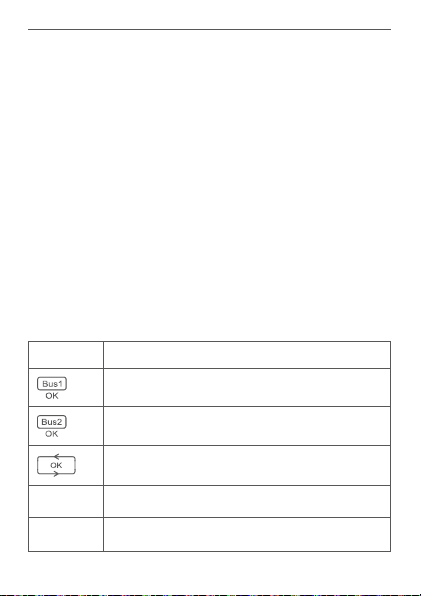
Displayübersicht (s. Abbildung 1):
Symbol Bedeutung
BUS1 OK
BUS2 OK
Ringtopologie („Loop“) OK
Daten werden vom Bus empfangen
Daten werden zum Bus gesendet
13
Page 14

Allgemeine Systeminformationen
V
E
C
D
F
G
Temperaturangabe (im Gerät)
Spannungsangabe (Eingangs- bzw. Ausgangsspannung an den Busklemmen)
Stromangabe (Gesamtstrom oder Strom
der einzelnen Busse)
4 Allgemeine Systeminformationen
Dieses Gerät ist Teil des Homematic IP Smart-HomeSystems und kommuniziert über das HomematicIP Pro
tokoll. Sie haben die Möglichkeit, alle Geräte des Systems
komfortabel und individuell über die Bedienoberfläche
der Zentrale CCU3 oder flexibel per Smartphone über
die HomematicIP App in Verbindung mit der Homema
tic IP Cloud zu konfigurieren. Welcher Funktionsumfang
sich innerhalb des Systems im Zusammenspiel mit wei
teren Komponenten ergibt, entnehmen Sie bitte dem
HomematicIP Wired Systemhandbuch. Alle technischen
Dokumente und Updates finden Sie stets aktuell unter
www.eQ-3.de.
14
-
-
-
Page 15

Systemvoraussetzungen
5 Systemvoraussetzungen
Das Homematic IP Wired System nutzt Bus-Datenleitungen für die interne Kommunikation zwischen den Wired
Geräten. Während die Bus-Verbindungsleitungen für die
schaltschrankinterne Verkabelung bereits im Lieferumfang
enthalten sind, wird für die Verkabelung externer Geräte
eine vieradrige Busleitung für die Kommunikation benötigt.
Für die Spannungsversorgung des Homematic IP Wired
Systems benötigen Sie ein separates Netzteil (s. „7.3 Auswahl der Spannungsversorgung“ auf Seite 20).
Für die Inbetriebnahme und Konfiguration der Wired Geräte muss ein Router mit Netzwerk- und Internetverbindung vorhanden sein.
Die Einrichtung und Bedienung des Wired Systems kann
lokal per Zentrale CCU3 erfolgen. Dafür benötigen Sie
einen Laptop, einen PC oder ein Tablet mit aktuellem Betriebssystem.
Alternativ können Sie Ihr Wired System flexibel per Smartphone (mit aktuellem Android- oder iOS-Betriebssystem)
über die Homematic IP Cloud in Verbindung mit der
Homematic IP App einrichten und steuern.
Detaillierte Informationen zu den Systemvoraussetzungen und zur Installationsplanung finden Sie im Homematic IP Wired Systemhanduch (zu finden im Downloadbereich unter www.eQ-3.de).
15
Page 16
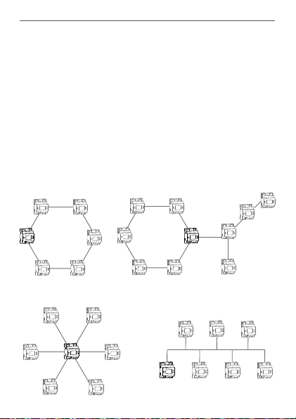
Topologie des Bussystems
Ringtopologie
6 Topologie des Bussystems
Die Homematic IP Wired Geräte werden für eine störsichere und robuste Verbindung untereinander über Busleitungen verbunden. Die Topologie des Busses, über den die
einzelnen Homematic IP Wired Komponenten verbunden
werden, kann beliebig aufgebaut werden. Die folgende
Abbildung stellt die möglichen Topologien beispielhaft
und lediglich symbolisch dar (keine Anschlusszeichnung).
6.1 Mögliche Anschlusstopologien
Ringtopologie
mit abgesetzten Strängen
Wired
Access
Point
Sterntopologie
16
Wired
Access
Point
Wired
Access
Point
Bustopologie
Wired
Access
Point
Page 17

Topologie des Bussystems
6.2 Betriebsarten
6.2.1 Ringtopologie
Erstmalig für einen Haus- und Gebäudebus können mit
Homematic IP Wired auch fehlertolerante Netze sehr
einfach aufgebaut werden, durch die selbst bei einer Unterbrechung der Leitungen keinerlei Ausfall von Geräten
und Funktionen folgt. Der Homematic IP Wired Bus unterstützt hierzu den Aufbau einer Ringtopologie („Loop“).
Der Bus wird vom Homematic IP Wired Access Point immer von einem zum nächsten Gerät und zuletzt wieder
zum HomematicIP Wired Access Point geführt, so dass
eine Schleife entsteht. Der Wired Access Point überprüft,
ob die Daten auf dem Bus an beiden Busanschlüssen
ankommen. Wird die Leitung an einer Stelle des Rings
unterbrochen, stellt sich die Ringtopologie automatisch
auf zwei unabhängige Busstränge um, sodass die Geräte
weiterhin in Betrieb bleiben.
6.2.2 Zwei separate Busse
Die beiden Busanschlüsse des Wired Access Points können auch als zwei separate Busstränge betrieben werden.
Dabei kann z. B. ein Bus für die Geräte innerhalb der Verteilung genutzt werden. Der andere Bus kann für Geräte der Feldinstallation (z. B. Unterputz-Geräte) oder für
Geräte in weiteren Unterverteilungen verwendet werden.
Der Wired Access Point leitet die Daten in diesem Betriebsmodus automatisch vom einen zum anderen Bus
weiter.
17
Page 18
Inbetriebnahme
7 Inbetriebnahme
7.1 Installationshinweise
Beachten Sie bei der Installation die Gefahrenhinweise gemäß „2 Gefahrenhinweise“ auf Seite 8.
Beachten Sie die auf dem Gerät angegebene Abisolierlänge der anzuschließenden Leiter.
Aus Gründen der elektrischen Sicherheit darf
zum Anschluss des Homematic IP Wired Bus (I
und H) ausschließlich das mitgelieferte Homematic IP Wired Buskabel oder ein als Zubehör
erhältliches eQ-3 Homematic IP Wired Buskabel
anderer Länge verwendet werden.
Starre Leiter können zum Anschließen direkt in die
Klemmstelle gesteckt werden (Push-In-Technik).
Zum Anschließen flexibler Leiter und zum Lösen
aller Arten von Leitern, ist der weiße Betätigungs
drücker oben auf den Klemmen zu drücken.
Die Busanschlüsse (I) und (J) bzw. (H) und (G) sind
parallel geschaltet. Somit kann das kommende
bzw. gehende Buskabel an einen beliebigen der
beiden Anschlüsse angeschlossen werden.
Hinweis! Installation nur durch Personen mit
einschlägigen elektrotechnischen Kenntnissen
und Erfahrungen!*
18
-
Page 19

Inbetriebnahme
Durch eine unsachgemäße Installation gefährden Sie
• Ihr eigenes Leben;
• das Leben der Nutzer der elektrischen Anlage.
Mit einer unsachgemäßen Installation riskieren Sie
schwere Sachschäden, z. B. durch Brand. Es droht für Sie
die persönliche Haftung bei Personen- und Sachschäden.
Wenden Sie sich an einen Elektroinstallateur!
Erforderliche Fachkenntnisse für die Installation:
*
Für die Installation sind insbesondere folgende Fachkenntnisse erforderlich:
• Die anzuwendenden „5 Sicherheitsregeln“:
Freischalten; gegen Wiedereinschalten sichern;
Spannungsfreiheit feststellen; Erden und Kurzschließen;
benachbarte, unter Spannung stehende Teile abdecken
oder abschranken;
• Auswahl des geeigneten Werkzeuges, der Messgeräte
und ggf. der persönlichen Schutzausrüstung;
• Auswertung der Messergebnisse;
• Auswahl des Elektroinstallationsmaterials zur Sicherstellung der Abschaltbedingungen;
• IP-Schutzarten;
• Einbau des Elektroinstallationsmaterials;
• Art des Versorgungsnetzes (TN-System, IT-System,
TT-System) und die daraus folgenden Anschlussbedingungen (klassische Nullung, Schutzerdung, erforderliche
Zusatzmaßnahmen etc.).
19
Page 20

Inbetriebnahme
7.2 Zugelassene Leitungsquerschnitte
Zugelassene Leitungsquerschnitte zum Anschluss an den
Wired Access Point sind:
Starre Leitung [mm2] Flexible Leitung ohne
Aderendhülse [mm2]
0,25-1,50 0,25-1,50
7.3 Auswahl der Spannungsversorgung
Die Spannungsversorgung des Homematic IP Wired Access Points erfolgt über ein separates Netzteil. Verwenden Sie für die Spannungsversorgung ein Netzteil, das für
den Einsatz in der Gebäudeautomation vorgesehen ist.
Die Basisanforderungen für diese Netzteil sind:
• Ausgangsspannung: 24 V
bar), <50 mVss, SELV
• max. 10 A, strombegrenzt
• kurzschlussfest
• mind. 3750 V Isolationsspannung (Ein-/Ausgang)
• Überspannungskategorie III
• EMV-Störfestigkeit gemäß EN61000-6-2
• Netzausfallüberbrückung: min. 80 ms
DC (±5%, bzw. einstell-
Sie können bspw. Netzteile aus der Step Power Serie des
Herstellers PHOENIX CONTACT verwenden (z. B. 24 V
DC,
2,5 A: STEP-PS/1AC/24DC/2.5).
20
Page 21

Inbetriebnahme
Beachten Sie bei der Auswahl des Netzteils, dass
die Zuleitung vom Netzteil zum Wired Access
Point maximal 3 m betragen darf.
Jeder Busstrang kann maximal 3 A Dauerstrom
liefern, sofern das Netzteil entsprechend ausgelegt ist.
21
Page 22

Inbetriebnahme
-
maticIP
Home
EIB-
Kabel
JY(ST)
Y 4x2
JY(ST)Y
2x2
Cat5e nach
Wired
Kabel
lt. VDE
0815
lt. VDE
0815
(EU-Stand.)
TIA568A
Blau/Weiß Rot Rot Rot Rot
mende
Buslei-tungen
Grün/Weiß - Weiß - -
hende
Buslei-tungen
Funktion Ethernet
7.4 Vorschlag zur Kabelbelegung und Farbzuordnung
22
DC) kom-
+ (24 V
- (GND, Masse) Blau Schwarz Blau Schwarz Schwarz
A (RS-485) Orange/Weiß Weiß Weiß Weiß Weiß
B (RS-485) Orange Gelb Gelb Gelb Gelb
DC) abge-
+ (24 V
- (GND, Masse) Grün - Grün - -
A (RS-485) Braun/Weiß - Weiß - -
B (RS-485) Braun - Braun - -
Sofern Sie ein abgeschirmtes Kabel verwenden, ist der Beidraht (Schirm) nur am
Wired Access Point auf die „-“ Klemme aufzulegen.
Page 23

Inbetriebnahme
7.5 Montage und Installation
Bitte lesen Sie diesen Abschnitt erst vollständig,
bevor Sie mit der Installation beginnen.
Bitte notieren Sie sich vor der Installation die auf
dem Gerät angebrachte Gerätenummer (SGTIN)
und den Verwendungszweck, damit Sie das Gerät
im Nachhinein leichter zuordnen können. Alternativ steht die Gerätenummer auch auf dem beiliegenden QR-Code-Aufkleber.
Für die Installation des Wired Access Points auf einer Hutschiene in einem Stromkreisverteiler gehen Sie wie folgt
vor:
• Schalten Sie den Stromkreisverteiler frei und decken Sie ggf. spannungsführende Teile ab (s. Sicherheitsregeln).
• Entfernen Sie die Abdeckung des Stromkreisverteilers.
• Setzen Sie den Wired Access Point auf die Hutschiene auf (s. Abbildung 3). Achten Sie darauf,
dass die Schrift auf dem Gerät und im Display für
Sie lesbar ist und die Anschlussklemmen für die
Versorgungsspannung
• Achten Sie bei der Montage darauf, dass die Rastfeder komplett einrastet und das Gerät fest auf
der Schiene sitzt.
• Stecken Sie das Netzwerkkabel in den Ethernet-
(B)
oben liegen.
23
Page 24

Inbetriebnahme
Anschluss (F) und verbinden Sie es mit einem
Router.
• Schließen Sie ein zuvor installiertes 24 V-Netzteil
über den Eingang für die Versorgungsspannung
(B) polungsrichtig an den Wired Access Point an.
• Schließen Sie das Bus-Verbindungskabel an den
Busanschluss 1 (I bzw. J) oder Busanschluss 2 (H
bzw. G) an und verbinden Sie alle weiteren Wired
Geräte über den Bus (s. Abbildung 4) (s. „6 Topologie des Bussystems“ auf Seite 16).
• Setzen Sie den mitgelieferten Bus-Blindstopfen
ein, wenn Busanschluss 1 oder Busanschluss 2
nicht benötigt werden.
• Setzen Sie die Abdeckung des Stromkreisverteilers wieder auf.
• Schalten Sie die Haussicherung wieder ein.
Nach der Installation und vor dem Anlernen des
Geräts an die App, stehen Ihnen bereits einfache
Bedienfunktionen (ggf. für Testzwecke) direkt am
Gerät zur Verfügung (s. „8 Bedienung“ auf Seite
29).
24
Page 25

Inbetriebnahme
7.6 Einrichtungs- und Anlernmöglichkeiten
Bitte lesen Sie diesen Abschnitt erst vollständig,
bevor Sie mit dem Anlernen beginnen.
Weiterführende Details und Übersichten zu den
Einrichtungsmöglichkeiten finden Sie im Homematic IP Wired Systemhandbuch.
Sie haben die Möglichkeit, den Wired Access Point
für eine lokale Konfiguration per PC an die Zentrale
CCU3 anzulernen und anschließend über die WebUI
Bedienoberfläche zu konfigurieren.
Alternativ können Sie den Wired Access Point für eine
flexible Steuerung per Homematic IP SmartphoneApp an die Homematic IP Cloud anlernen. Dabei ist es
möglich, das Wired System
• per Smartphone-App direkt über den HomematicIP Wired Access Point (HmIPW-DRAP) zu steuern oder
• mit Homematic IP Funk-Komponenten über den
Homematic IP Access Point (HmIP-HAP) zu kombinieren.
Weitere Informationen zur Einrichtung der WebUI
Bedienoberfläche und zum Anlernen weiterer
Geräte finden Sie in der Bedienungsanleitung der
Zentrale CCU3.
25
Page 26

Inbetriebnahme
7.6.1 Anlernen an die Zentrale CCU3
Um die Kommunikation zwischen dem Wired Access
Point und der Zentrale CCU3 herzustellen und weitere
Wired Geräte über die WebUI Bedienoberfläche steuern
zu können, gehen Sie wie folgt vor:
• Richten Sie zunächst Ihre Zentrale CCU3 gemäß
der zugehörigen Bedienungsanleitung ein.
• Starten Sie die Benutzeroberfläche „Homematic
WebUI“ auf Ihrem PC.
• Klicken Sie unter „Einstellungen“ auf „Systemsteuerung“ im rechten oberen Bereich des Browserfensters.
• Klicken Sie im nächsten Fenster auf „HomematicIP Access Point“.
26
Page 27

Inbetriebnahme
Homematic IP
Access Points
• Folgen Sie den weiteren Anweisungen in der Bedienoberfläche.
Weitere Informationen zur Einrichtung des Wired
Access Points finden Sie im Homematic IP Wired
Systemhandbuch (zu finden im Downloadbereich
unter www.eQ-3.de).
7.6.2 Anlernen an die Homematic IP Cloud per
Homematic IP App
Wenn Sie Ihre Homematic IP Wired Geräte flexibel per
Smartphone-App steuern möchten, können Sie den Wired Access Point einfach an die HomematicIP Cloud anlernen. Gehen Sie dazu wie folgt vor:
• Laden Sie die Homematic IP App für Android oder
iOS im jeweiligen App-Store herunter und installieren Sie die App auf Ihrem Smartphone.
27
Page 28

Inbetriebnahme
• Starten Sie die Homematic IP App.
• Folgen Sie den Anweisungen in der App, um den
Wired Access Point mit der Cloud zu verbinden.
• Scannen Sie den QR-Code des Wired Access
Points. Alternativ können Sie die Gerätenummer
(SGTIN) manuell in der App eingeben. Beides
können Sie dem beiliegenden QR-Code-Aufkleber entnehmen.
• Wenn die LED Ihres Wired Access Points dauerhaft blau leuchtet, bestätigen Sie dies in der App.
• Bei einem anderen Blinkverhalten der LED folgen
Sie den Anweisungen in der App oder s. „9 Fehlercodes und Blinkfolgen“ auf Seite 31.
• Der Wired Access Point wird am Server registriert.
Dies kann einige Minuten dauern. Bitte warten
Sie.
• Bei erfolgreicher Registrierung drücken Sie die
Systemtaste (A) Ihres Wired Access Points zur
Bestätigung.
• Das Anlernen wird durchgeführt.
• Der Wired Access Point ist nun eingerichtet und
sofort einsatzbereit.
Nachdem der Wired Access Point erfolgreich eingerichtet
wurde, können Sie weitere Homematic IP Wired Geräte
anlernen. Weitere Informationen dazu entnehmen Sie der
Bedienungsanleitung des jeweiligen Geräts.
28
Page 29

Bedienung
Wenn Sie bereits Homematic IP Geräte im SmartHome-System nutzen oder Ihre Wired Geräte mit
Funk-Komponenten von Homematic IP kombinie
ren möchten, können Sie die Homematic IP Wired
Geräte auch einfach an einen (bestehenden)
Homematic IP Access Point anlernen. Lernen Sie
dazu den Homematic IP Wired Access Point ge
mäß der zugehörigen Bedienungsanleitung an den
(bestehenden) Homematic IP Access Point an.
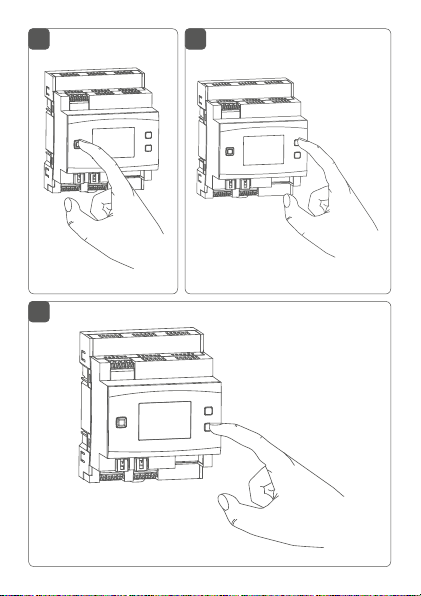
8 Bedienung
Über die drei Geräte-Tasten stehen Ihnen folgende Bedienfunktionen direkt am Gerät zur Verfügung:
• Systemtaste (A) (s. Abbildung 5)
• Mode-Taste (C) (s. Abbildung 6)
• Select-Taste (D) (s. Abbildung 7)
Displaybeleuchtung
Durch kurzes Drücken der Systemtaste können Sie die
LCD-Hintergrundbeleuchtung bei allen an den Bus angeschlossenen Geräten aktivieren.
Werte anzeigen
Durch kurzes Drücken der Mode-Taste können Sie zwischen den einzelnen oder beiden Bussträngen wählen:
• Einmal drücken = Bus 1
• Zweimal drücken = Bus 2
29
-
-
Page 30

Bedienung
• Dreimal drücken = Bus 1 und Bus 2
Durch kurzes Drücken der Select-Taste schalten Sie zwischen den folgenden Werten:
• Für die einzelnen Busstränge werden Spannung
und Strom (nur Werte > 100 mA) angezeigt.
• Für die einzelnen oder beiden Busstränge werden
Eingangsspannung und Gesamtstrom für beide
Busse sowie die Temperatur im Gehäuse angezeigt.
Bus-Betriebsmodus einstellen
Durch langes Drücken der Mode-Taste können Sie zur
Konfiguration des Bus-Betriebsmodus (einzelne Busstränge oder Ring) wechseln.
Mit der Select-Taste können Sie zwischen den Betriebsmodi als einzelne Busstränge (für Bus 1 und Bus 2) oder
Ring wechseln. Durch kurzes Drücken auf die Mode-Taste wird die Konfiguration übernommen.
Kurzschlussfehler quittieren
Wenn die Versorgungsspannung am Bus kurzgeschlossen wurde (E15, vgl. „9 Fehlercodes und Blinkfolgen“ auf
Seite 31), muss dieser Fehler durch den Benutzer quittiert werden. Durch langes Drücken der Select-Taste können Sie zur Fehler-Quittierung wechseln.
Durch kurzes Drücken der Select-Taste können Sie zwischen den Fehlern wählen. Durch kurzes Drücken der
Mode-Taste wird der Fehler quittiert.
30
Page 31

Fehlercodes und Blinkfolgen
9 Fehlercodes und Blinkfolgen
Blinkcode/
LCD-Anzeige
Dauerhaft
oranges
Leuchten
Schnelles
blaues
Blinken
Dauerhaft
blaues
Leuchten
Dauerhaft
türkises
Leuchten
Schnelles
gelbes
Blinken
Dauerhaft
gelbes
Leuchten
Bedeutung Lösung
Wired Access
Point startet
Verbindung
zum Server wird
aufgebaut
Standardbetrieb,
Verbindung zum
Server aufgebaut
Routerfunktion
aktiv (bei Betrieb
mehrerer Access
Points)
Keine Verbindung zum
Netzwerk bzw.
zum Router
Keine Internetverbindung
Warten Sie kurz
ab und achten Sie
auf das folgende
Blinkverhalten.
Warten Sie bis die
Verbindung aufgebaut wurde und die
LED dauerhaft blau
leuchtet.
Sie können mit der
Bedienung fortfahren.
Sie können mit der
Bedienung fortfahren.
Verbinden Sie den
Access Point mit
dem Netzwerk/
Router.
Prüfen Sie die Internetverbindung und
ggf. die FirewallEinstellungen.
31
Page 32

Fehlercodes und Blinkfolgen
Abwechselnd
langes und
Update wird
durchgeführt
kurzes oranges Blinken
Schnelles
rotes
Fehler beim
Update
Blinken
Schnelles
oranges
Blinken
Vorstufe zum
Zurücksetzen in
Werkseinstel-
lungen
1x langes
grünes
Zurücksetzen
bestätigt
Leuchten
1x langes
rotes
Zurücksetzen
fehlgeschlagen
Leuchten
E11 Temperatur zu
hoch
E14 Kurzschluss
zwischen Daten-
leitung und 24 V
32
Warten Sie, bis das
Update abgeschlossen wurde.
Prüfen Sie die Server- und Internetverbindung. Starten
Sie den Access
Point neu.
Drücken Sie die Systemtaste erneut für
4 s, bis die LED grün
aufleuchtet.
Sie können mit der
Bedienung fortfahren.
Versuchen Sie es
erneut.
Reduzieren Sie die
angeschlossene
Last und lassen Sie
das Gerät abkühlen.
Beheben Sie den
Kurzschluss.
Page 33

Wiederherstellung der Werkseinstellungen
E15 Die konfigu-
rierte und die
tatsächliche
Bus-Verkabelung
stimmen nicht
überein.
E16 Kurzschluss der
Spannungsver-
sorgung
Überprüfen Sie
die Bustopologie
oder passen Sie die
Einstellungen an.
Beseitigen Sie ggf
Fehler.
Beheben Sie den
Kurzschluss und
quittieren Sie den
Fehler (s. „8 Bedienung“ auf Seite
29).
10 Wiederherstellung der
Werkseinstellungen
Die Werkseinstellungen des Geräts können wiederhergestellt werden. Dabei gehen alle Einstellungen verloren.
Um die Werkseinstellungen des Wired Access Points wiederherzustellen, gehen Sie wie folgt vor:
• Drücken Sie für 4 s auf die Systemtaste (A), bis
die LED (A) schnell orange zu blinken beginnt (s.
Abbildung 5).
• Lassen Sie die Systemtaste wieder los.
• Drücken Sie die Systemtaste erneut für 4 s, bis die
LED grün aufleuchtet.
33
Page 34

Wartung und Reinigung
• Lassen Sie die Systemtaste wieder los, um das
Wiederherstellen der Werkseinstellungen abzuschließen.
Das Gerät führt einen Neustart durch. Nach dem Neustart
können Sie das Gerät wieder ins System integrieren.
11 Wartung und Reinigung
Das Gerät ist wartungsfrei. Überlassen Sie eine
Wartung oder Reparatur einer Fachkraft.
Schalten Sie vor Ausbau des Geräts unbedingt die
Netzspannung frei (Sicherungsautomat abschalten)! Arbeiten am 230 V-Netz dürfen nur von einer Elektro-Fachkraft (nach VDE 0100) erfolgen.
Reinigen Sie das Gerät mit einem weichen, sauberen,
trockenen und fusselfreien Tuch. Verwenden Sie keine
lösemittelhaltigen Reinigungsmittel, das Kunststogehäuse und die Beschriftung können dadurch angegrien
werden.
34
Page 35

Technische Daten
12 Technische Daten
Geräte-Kurzbezeichnung:
Versorgungsspannung: 24 VDC, ±5 %, SELV
Leitungslänge DC-Eingang: 3 m max.
Stromaufnahme: 6 A max./55 mA typ.
Stromaufnahme im
Ruhebetrieb ohne
angeschlossene Geräte: 55 mA
Leistungsaufnahme
Ruhebetrieb: 1320 mW
Busausgänge 2x Homematic IP Wired
Länge HmIPW Bus: 300 m max.
Anzahl Geräte pro Bus: 64 max.
Verlustleistung des Geräts
für Wärmeberechnung: max. 2,4 W
Leitungsart und -querschnitt: starre und flexible Leitung,
Installation:
Schutzart: IP20
Umgebungstemperatur: -5 bis +40 °C
Abmessungen (B x H x T): 72 x 90 x 69 mm (4 TE)
Gewicht: 150 g
Netzwerk: 10/100 MBit/s, Auto-MDIX
HmIPW-DRAP
Bus (24 V
Busausgang, RS485 Bus)
0,25-1,5 mm²
auf Tragschiene (Hutschiene, DIN-Rail) gemäß
EN60715
DC; max. 3 A pro
35
Page 36

Technische Daten
Technische Änderungen vorbehalten.
Entsorgungshinweis
Gerät nicht im Hausmüll entsorgen! Elektronische Geräte sind entsprechend der Richtlinie
über Elektro- und Elektronik-Altgeräte über die
örtlichen Sammelstellen für Elektronik-Altgeräte
zu entsorgen.
Konformitätshinweis
Das CE-Zeichen ist ein Freiverkehrszeichen, das
sich ausschließlich an die Behörden wendet und
keine Zusicherung von Eigenschaften beinhaltet.
Bei technischen Fragen zum Gerät wenden Sie
sich bitte an Ihren Fachhändler.
36
Page 37

Package contents
Quantity Description
1 Homematic IP Wired Access Point
1 Bus connection cable
1 Bus blind plug
1 Network cable
1 User manual
Documentation © 2018 eQ-3 AG, Germany.
All rights reserved. Translation from the original version in German. This manual may not be reproduced in any format, either in
whole or in part, nor may it be duplicated or edited by electronic,
mechanical or chemical means, without the written consent of
the publisher.
Typographical and printing errors cannot be excluded. However,
the information contained in this manual is reviewed on a regular
basis and any necessary corrections will be implemented in the
next edition. We accept no liability for technical or typographical
errors or the consequences thereof.
All trademarks and industrial property rights are acknowledged.
Printed in Hong Kong
Changes may be made without prior notice as a result of technical advances.
152467 (web)
Version 1.4 (09/2018)
37
Page 38

Table of contents
1 Information about this manual....................................39
2 Hazard information ........................................................39
3 Function and device overview ....................................43
4 General system information ........................................45
5 System requirements .................................................... 46
6 Topology of the bus system.........................................47
6.1 Possible connecting topologies .......................................47
6.2 Operating modes ................................................................48
6.2.1 Ring topology ......................................................... 48
6.2.2 Two separate buses ...............................................48
7 Start-up ........................................................................... 49
7.1 Installation instructions ..................................................... 49
7.2 Permissible cable cross sections ......................................51
7.3 Selecting the supply voltage .............................................51
7.4 Recommendation for cable occupation and
colour allocation ................................................................. 53
7.5 Mounting and installation ................................................. 54
7.6 Set-up and teach-in options .............................................55
7.6.1 Connecting to the Homematic IP Central
Control Unit CCU3 ................................................ 56
7.6.2 Teaching-in to the Homematic IP cloud via
8 Operation .........................................................................59
9 Error codes and flashing sequences ..........................61
10 Restore factory settings ................................................63
11 Maintenance and cleaning .......................................... 64
12 Technical specifications ................................................65
38
Homematic IP app ................................................. 58
Page 39

Information about this manual
1 Information about this manual
Please read this manual carefully before beginning operation with your Homematic IP Wired component. Keep
the manual so you can refer to it at a later date if you
need to.
If you hand over the device to other persons for use,
please hand over this manual as well.
Symbols used:
Attention!
This indicates a hazard.
Please note: This section contains important additional information.
2 Hazard information
Do not open the device. It does not contain any
parts that can be maintained by the user. There is
a risk of electric shock if the device is opened. If
you have any doubts, have the device checked by
an expert.
For safety and licensing reasons (CE), unauthorized change and/or modification of the device is
not permitted.
39
Page 40

Hazard information
Do not use the device if there are signs of damage to the housing, control elements or connecting sockets, for example. If you have any doubts,
have the device checked by an expert.
The device may only be operated in dry and dustfree environment and must be protected from
the eects of moisture, vibrations, solar or other
methods of heat radiation, cold and mechanical
loads.
The device is not a toy; do not allow children to
play with it. Do not leave packaging material lying
around. Plastic films/bags, pieces of polystyrene,
etc. can be dangerous in the hands of a child.
We do not assume any liability for damage to
property or personal injury caused by improper
use or the failure to observe the hazard information. In such cases, any claim under warranty is
extinguished! For consequential damages, we assume no liability!
Before installation and connection of the device,
mains voltage must be disconnected and live
parts in the surrounding must be covered.
40
Page 41

Hazard information
The Wired Access Point is part of the building
installation. The relevant national standards and
directives must be taken into consideration
during planning and set-up. The Wired Access
Point is intended for operation within the
HomematicIP Wired bus only. The Homematic IP
Wired bus is a SELV power circuit. The power
supply of the building installation and the
Homematic IP Wired bus have to be laid
separately. Common cable routing for power
supply and the Homematic IP Wired bus in
installation and junction boxes is not permitted.
The required isolation for power supply of the
building installation to the Homematic IP Wired
bus must be observed at all times. Noncompliance with the installation instructions can
cause fire or introduce other hazards.
The 24 V supply voltage (B), the Ethernet cable (F)
as well as Ethernet or telecommunication lines of
the Homematic IP Wired bus that are connected
to the bus connections (J and G) are SELV power
circuits. These wires must be routed separately
from mains voltage cables by measures for secure separation (e.g. with horizontal and vertical
barrier strips).
41
Page 42

Hazard information
For secure operation, the device has to be installed
in a power distribution panel according to VDE
0603, DIN 43871 (low-voltage sub-distribution
board), DIN 18015-x. The installation must be
carried out on a mounting rail (DIN rail) according
to EN 60715. Installation and wiring have to be
performed according to VDE 0100 (VDE 0100-410,
VDE 0100-510 etc.). Please consider the technical
connection requirements (TAB) of your energy
supplier.
When connecting to the device terminals, take
the permissible cables and cable cross sections
into account.
The device may only be operated within domestic environment, in business and trade areas as
well as in small enterprises.
If you use the device/system in a security application it has to be operated in connection with an
UPS (uninterruptible power supply) in order to
bridge possible power failure.
Using the device for any purpose other than that
described in this operating manual does not fall
within the scope of intended use and shall invalidate any warranty or liability.
42
Page 43

Function and device overview
3 Function and device overview
The Homematic IP Wired Access Point is the central interface of the Homematic IP Wired system and oers supply
voltage for the entire bus in combination with a power
supply unit. The device is simply connected via Ethernet
cable to a router and connects the Central Control Unit
CCU3 or the Homematic IP cloud service with the wired
devices. The configuration of the Homematic IP Wired
system is carried out via a Central Control Unit CCU3 or
via cloud, using the free Homematic IP app.
The Homematic IP Wired Access Point is easily installed to
a DIN rail within the electrical distribution board. The bus
connection cables oer quick and easy installation thanks
to pre-assembled cables with plug connectors. The wires
are connected and disconnected quickly and screwless
thanks to spring-loaded terminals.
The integrated LC display with background lighting can
be used to check the correct wiring of the building installation directly at site without having to carry out complex
programming.
In combination with the Homematic IP Access Point
(HmIP-HAP) for wireless communication, also wireless
Homematic IP components can be integrated at any
time.
43
Page 44

Function and device overview
RX
1 1
RX
TX
1 1
Device overview (see figure 1):
(A) System button (teach-in/pairing button and LED)
Input for supply voltage
(B)
(C) Mode button
(D) Select button
(E) LC display
(F) Ethernet connection
Bus terminator 2 clamp terminal
(G)
(H) Bus terminator 2 socket
(I) Bus terminator 1 socket
(J) Bus terminator 1 clamp terminal
Display overview (see figure 1):
Symbol Meaning
BUS1 OK
BUS2 OK
Ring topology (“loop”) OK
Data is received by the bus
Data is sent to the bus
44
Page 45

General system information
V
E
C
D
F
G
Temperature indication (in device)
Voltage indication (input or output voltage
at bus terminals)
Current indication (total current or current
of single bus)
4 General system information
This device is part of the Homematic IP smart home
system and works with the Homematic IP protocol. All
devices of the system can be configured comfortably
and individually with the user interface of the Central
Control Unit CCU3 or flexibly via the Homematic IP
smartphone app in connection with the Homematic IP
cloud. All available functions provided by the system
in combination with other components are described
in the Homematic IP Wired Installation Guide. All cur
rent technical documents and updates are provided at
www.eQ-3.com.
-
45
Page 46

System requirements
5 System requirements
The Homematic IP Wired system uses the bus data line
for internal communication between the wired devices.
While the bus connecting cables for wiring within the
control cabinet are already included in the package content, a four-wire bus line is required for communication
of external devices.
For supply voltage of the Homematic IP Wired system, a
separate power supply unit is required (see „7.3 Selecting
the supply voltage“ on page 51).
A router with network and Internet connection is required
for setup and configuration of the wired devices.
Installation and operation of the wired system is carried
out via Central Control Unit CCU3. Therefore, you will
need a laptop, PC or tablet with a current operating system.
Alternatively, you can flexibly control your wired system
with your smartphone (with current Android or iOS operating system) via the Homematic IP cloud in connection
with the Homematic IP app.
Detailed information about system requirements and
installation can be found in the Homematic IP Wired
System Manual (available in the download area of
www.eQ-3.com).
46
Page 47

Topology of the bus system
ring topology
6 Topology of the bus system
For interfence-proof and robust connection, the Homematic IP Wired devices are connected via bus lines. The
topology of the bus that connects the single Homematic
IP Wired components can be established as required. The
following figure shows possible topologies as example (no
connecting diagram).
6.1 Possible connecting topologies
ring topology
with remote lines
Wired
Access
Point
star topology
Wired
Access
Point
Wired
Access
Point
bus topology
Wired
Access
Point
47
Page 48

Topology of the bus system
6.2 Operating modes
6.2.1 Ring topology
For the first time, Homematic IP Wired oers easy installation of fault-tolerant networks for a house or building
bus system. Even in case of interruptions of the lines,
there will be no device or function failures. The HomematicIP Wired bus does therefore support the setup of
a ring topology (“loop”). The bus is always connected
from the Homematic IP Wired Access Point to the next
device and finally back to the Homematic IP Wired Access Point, so that a loop is established. The Wired Access
Point checks, if the data on the bus is carried to both bus
connections. If the line is interrupted at one part of the
ring, the bus topology is restructured automatically into
two independent bus lines, so that the devices keep on
working correctly.
6.2.2 Two separate buses
The both bus connections of the Wired Access Point can
be operated also as two separate bus lines. Thus, e.g. one
bus can be used with the devices within the distribution
board. The second bus can then be used for devices of
the field installation (e.g. flush-mounted devices) or for
devices in additional sub-distribution boards.
The Wired Access Point automatically transfers the data
in this operating mode from one bus to another.
48
Page 49

7 Start-up
7.1 Installation instructions
Please observe the hazard information in section
„2 Hazard information“ on page 39 during in
stallation.
Start-up
-
Please note the insulation stripping length of the
conductor to be connected, indicated on the de
vice.
For electrical safety reasons, only the supplied
Homematic IP Wired Bus Cable may be used for
connecting the device to the Homematic IP
Wired bus (I and H). Furthermore, an eQ-3
Homematic IP Wired Bus Cable with other
lengths (available as accessory) can be used.
Rigid cables can be plugged directly into the
clamp terminal (push-in technology). To connect
flexible cables or to loosen any kind of conduc
tors, the white actuation lever at the top of the
clamp has to be pressed.
The bus terminators (I) and (J) or (H) and (G) are
switched in parallel. However, the incoming or
outgoing bus cable can be connected to any of
the two connections.
-
-
49
Page 50

Start-up
Please note! Only to be installed by persons with
the relevant electro-technical knowledge and
experience!*
Incorrect installation can put
• your own life at risk;
• and the lives of other users of the electrical system.
Incorrect installation also means that you are running the
risk of serious damage to property, e.g. because of a fire.
You may be personally liable in the event of injuries or
damage to property.
Contact an electrical installer!
*Specialist knowledge required for installation:
The following specialist knowledge is particularly important during
installation:
• The “5 safety rules” to be used:
Disconnect from mains; Safeguard from switching on
again; Check that system is de-energised; Earth and
short circuit; Cover or cordon o neighbouring live parts;
• Select suitable tool, measuring equipment and, if necessary, personal safety equipment;
• Evaluation of measuring results;
• Selection of electrical installation material for safeguarding shut-o conditions;
• IP protection types;
• Installation of electrical installation material;
• Type of supply network (TN system, IT system, TT system) and the resulting connecting conditions (classical
zero balancing, protective earthing, required additional
measures etc.).
50
Page 51

Start-up
7.2 Permissible cable cross sections
Permitted cable cross sections for connecting to the
Wired Access Point are:
Rigid cable [mm2] Flexible cable
without ferrule [mm2]
0.25-1.50 0.25-1.50
7.3 Selecting the supply voltage
Voltage is supplied to the Homematic IP Wired Access
Point via a separate power supply unit. Please use a power supply unit that is appropriate for application in house
installations. The basic requirements to the power supply
unit are:
• Output voltage: 24 V
<50 mVss, SELV
• 10 A max., current-limited
• short circuit-proof
• at least 3750 V isolation voltage (input and output)
• over-voltage category III
• EMV interference immunity according to
EN61000-6-2
• Power failure mains buering: at least 80 ms
For example, you can use power supply units of the Step
Power Series by PHOENIX CONTACT (e.g. 24 VDC, 2.5 A:
STEP-PS/1AC/24DC/2.5).
DC (±5%, or adjustable),
51
Page 52

Start-up
When selecting the power supply unit, please
note that the supply cable from the network to
the Wired Access Point may not exceed 3 m.
Every bus line can supply 3 A continuous current
max., as far as the power supply unit is able to
provide it.
52
Page 53

Homemat-
icIP Wired
Cable
Start-up
Yellow
7.4 Recommendation for cable occupation and colour allocation
EIB
cable
JY(ST)Y
4x2 acc.
VDE
JY(ST)Y
2x2 acc.
VDE
Cat5e acc.
TIA568A
Function Ethernet
0815
0815
(EU norm)
Blue/white Red Red Red Red
ing bus
+ (24 VDC) incom-
line
- (GND, ground) Blue Black Blue Black Black
White White White White
white
A (RS-485) Orange/
low
- White - -
- White - -
white
ing bus
cable
- (GND, ground) Green - Green - -
white
A (RS-485) Brown/
B (RS-485) Brown - Brown - -
If you are working with a shielded cable, the continuity wire (shield) may only be
connected to the “-” terminal of the Wired Access Point.
53
Green/
DC) outgo-
B (RS-485) Orange Yellow Yellow Yel -
+ (24 V
Page 54

Start-up
7.5 Mounting and installation
Please read this entire section before starting to
install the device.
Before installation, please note the device number (SGTIN) labelled on the device as well as the
exact application purpose in order to make later
allocation easier. You can also find the device
number on the QR code sticker supplied.
To install the Wired Access Point on a DIN rail within a
distribution board, please proceed as follows:
• Disconnect the power distribution panel and
cover any live parts, if required (see hazard information).
• Remove the cover of the power distribution panel.
• Place the Wired Access Point onto the DIN rail
(see fig. 3). Make sure that you can read the letters
on the device and display and that the connect
ing terminals for supply voltage
• During installation, make sure that the locating
springs engage properly and that the device is
securely seated on the rail.
• Plug-in the network cable into the Ethernet connecting socket (F) and connect it to your router.
• Connect a previously installed 24 V power supply unit via the input for supply voltage (B) to the
Wired Access Point, observing the correct polarity.
54
(B)
are at the top.
-
Page 55

Start-up
• Connect the bus connection cable to the bus
terminator 1 (I or J) or bus terminator 2 (H or G)
and connect all other wired devices via the bus
(see fig. 4) (see „6 Topology of the bus system“
on page 47).
• Use the supplied bus blind plug, if bus connection
1 or bus connection 2 are not needed.
• Reattach the cover of the power distribution panel.
• Switch the fuse of the power circuit back on
again.
After installation and before connecting the device to the app, simple operating functions (e.g.
for test purposes) are available directly on the device („8 Operation“ on page 59).
7.6 Set-up and teach-in options
Please read this entire section before starting
the teach-in procedure.
You will find further details and overviews about
the set-up options in the Homematic IP Wired
Installation Guide.
In this way, you can teach-in the Wired Access Point to
the Central Control Unit CCU3 for local configuration via
a PC using the WebUI user interface.
55
Page 56

Start-up
As an alternative, connect the Wired Access Point to the
Homematic IP cloud for flexible control via HomematicIP
smartphone app. You can
• control the wired system directly via smartphone
app using the Homematic IP Wired Access Point
(HmIPW-DRAP) or
• combine wired devices with wireless Homematic
IP devices via the Homematic IP Access Point
(HmIP-HAP).
For further information about setting up the WebUI user interface and about teaching-in further
devices, please refer to the user manual of the
CCU3.
7.6.1 Connecting to the Homematic IP Central Control Unit CCU3
To enable communication between the Wired Access
Point and the Central Control Unit CCU3 and for controlling additional Wired devices via the WebUI user interface,
please proceed as follows:
• First, set-up your Central Control Unit CCU3 according to the user manual.
• Start the user interface “Homematic WebUI” on
your computer.
• Click on “Settings” and “Control panel” in the
right-hand side of the screen.
56
Page 57

Start-up
• In the next window, click on “HomematicIP Access
Point”.
• Follow the instructions in the user interface.
Detailed information about setting up the Wired
Access Point can be found in the Homematic IP
Wired System Manual (available in the download
area of www.eQ-3.com).
57
Page 58

Start-up
7.6.2 Teaching-in to the Homematic IP cloud via
Homematic IP app
If you want to control your Homematic IP Wired devices
flexibly via smartphone app, you can simply connect the
Wired Access Point to the Homematic IP cloud. To do
this, please proceed as follows:
• Download the Homematic IP app for Android or
iOS in the app store and install the app on your
smartphone.
• Open the Homematic IP app.
• Follow the instructions in the app to connect the
Wired Access Point with your smartphone
• Please scan the QR code of your Wired Access
Point. You can also enter the device number
(SGTIN) manually. You will find both information
on the OR code sticker supplied.
• Please confirm in the app if the LED of your Wired
Access Point lights up permanently blue.
• If the LED lights up dierently, please follow the
instructions in the app or see „9 Error codes and
flashing sequences“ on page 61.
• The Wired Access Point is registered to the server.
This may take a few minutes. Please wait.
• After successful registration, please press the system button (A) of your Access Point for confirmation.
• Teaching-in will be carried out.
58
Page 59

Operation
• The Wired Access Point is now set up and immediately ready for use.
After the Wired Access Point has been set-up successfully, you can teach-in additional Homematic IP Wired
devices. For further information, please refer to the operating manual of the corresponding device.
If you are already using Homematic IP devices in
your smart home system or if you want to com
bine your Homematic IP Wired devices with wireless Homematic IP components, you can also
connect the Homematic IP Wired devices to an
(installed) Access Point. Therefore, connect the
Homematic IP Wired Access Point to the (installed)
Homematic IP Access Point, as described in the
user manual.
8 Operation
Via the device push-buttons, the following operating
functions are available directly on the device:
• System button (A) (see figure 5)
• Mode button (C) (see figure 6)
• Select button (D) (see figure 7)
Display light
By pressing the system button briefly, you can activate
59
-
Page 60

Operation
the LCD background lighting of all devices connected to
the bus.
Display values
You can select between the single or both bus lines by
pressing the mode button briefly:
• Pressing once = bus 1
• Pressing twice = bus 2
• Pressing three times = bus 1 and bus 2
You can switch between the following values by pressing
the select button:
• For the single bus lines, voltage and current (only
values > 100 mA) are displayed.
• For the single and both lines, input voltage and
total current for both bus lines as well as the tem
perature in the housing are displayed.
Setting the bus operating mode
Press and hold down the mode button to switch to the
configuration of the bus operating mode (single bus lines
or ring).
Use the select button to switch between the operating
modes of the single bus lines (for bus 1 and bus 2) or ring.
The configuration is saved after pressing the mode button.
Acknowledgement of short circuit failure
If the supply voltage on the bus is short-circuited (E15,
60
-
Page 61

Error codes and flashing sequences
see „9 Error codes and flashing sequences“ on page
61), the error must be acknowledged by the user.
Press and hold down the select button to change to the
error acknowledgement.
You can switch between the errors by pressing the select
button briefly. The error is acknowledged by pressing the
mode button briefly.
9 Error codes and flashing sequences
Flashing
code / LC
display
Permanent
orange lighting
Fast blue
flashing
Permanent
blue lighting
Meaning Solution
The Wired Access Point is
starting.
Connection to
the server is being established
Normal operation, connection
to server is
established
Please wait shortly
and observe the
subsequent flashing
behaviour.
Wait until the connection is established and the LED
lights permanently
blue.
You can continue
operation.
61
Page 62

Error codes and flashing sequences
Permanent
turquoise
lighting
Fast yellow
flashing
Permanent
yellow lighting
Alternately
long and
short orange
flashing
Fast red
flashing
Fast orange
flashing
1x long green
lighting
1x long red
lighting
62
Router function
active (when
You can continue
operation.
operating with
several Access
Points)
No connection
to network or
router
No Internet connection
Connect the Ac-
cess Point to the
network/router.
Please check the
Internet connection
and firewall settings.
Update in pro-
gress
Please wait until the
update has been
completed
Error during
update
Please check the
server and Internet
connection. Re-start
the Access Point.
Stage before
restoring the
factory settings
Press and hold
down the system
button again for 4
seconds, until the
LED lights up green.
Reset confirmed You can continue
operation.
Reset failed Please try again.
Page 63

Restore factory settings
E11 Temperature too
high
E14 Short circuit
between data
line and 24 V
E15 The configured
and actual bus
cabling does not
match.
E16 Short circuit of
supply voltage
Reduce the con-
nected load and
let the device cool
down.
Remove the short
circuit.
Please check the
bus topology and
adjust the settings.
Remove any errors.
Remove the short
circuit and ac-
knowledge the error
(see „8 Operation“
on page 59).
10 Restore factory settings
The factory settings of the device can be restored.
If you do this, you will lose all your settings.
To restore the factory settings of the Wired Access Point,
please proceed as follows:
• Press and hold down the system button (A) for 4
seconds until the LED (A) quickly starts flashing
orange (see figure 5).
• Release the system button again.
63
Page 64

Maintenance and cleaning
• Press and hold down the system button again for
4 seconds, until the LED lights up green.
• Release the system button to finish the procedure.
The device will perform a restart. After the restart, you can
again integrate your device into the system.
11 Maintenance and cleaning
The product does not require any maintenance.
Enlist the help of an expert to carry out any maintenance or repairs.
The mains voltage must be disconnected before
the device is removed (trip the miniature circuitbreaker). Only qualified electricians (to VDE 0100)
are permitted to carry out work on the 230 V
mains.
Clean the device using a soft, lint-free cloth that is clean
and dry. Do not use any detergents containing solvents,
as they could corrode the plastic housing and label.
64
Page 65

Technical specifications
12 Technical specifications
Device short description:
Supply voltage: 24 VDC, ±5 %, SELV
Line length DC input: 3 m max.
Current consumption: 6 A max./55 mA (typically)
Current consumption in
standby without
connected devices: 55 mA
Power consumption
in standby: 1320 mW
Bus outputs: 2x Homematic IP Wired
HmIPW bus length: 300 m max.
Number of devices per bus: 64 max.
Power loss of the device
for thermal calculation: 2.4 W max.
Cable type and cross section:
Installation:
Degree of protection: IP20
Ambient temperature: -5 to +40 °C
Dimensions (W x H x D): 72 x 90 x 69 mm
(4 WM width)
Weight: 150 g
Network: 10/100 MBit/s, Auto-MDIX
HmIPW-DRAP
Bus (24 V
bus output, RS485 Bus)
rigid and flexible cable,
0.25-1.5 mm²
mounting rail (DIN rail)
according to EN 60715
DC; max. 3 A per
65
Page 66

Subject to technical changes.
Instructions for disposal
Do not dispose of the device with regular domestic waste! Electronic equipment must be disposed of at local collection points for waste electronic equipment in compliance with the Waste
Electrical and Electronic Equipment Directive.
Information about conformity
The CE sign is a free trading sign addressed exclusively to the authorities and does not include
any warranty of any properties.
For technical support, please contact your retailer.
Page 67

Kostenloser Download der Homematic IP App!
Free download of the Homematic IP app!
Bevollmächtigter des Herstellers:
Manufacturer’s authorised representative:
eQ-3 AG
Maiburger Straße 29
26789 Leer / GERMANY
www.eQ-3.de
 Loading...