

Page 1
Installations- und
Bedienungsanleitung
Installation instruction and
operating manual
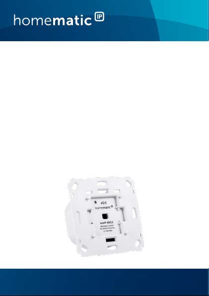
Wandtaster für Markenschalter –
2-fach
Remote Control for brand
switches – 2 channels
HmIP-BRC2
S. 2
p. 30
Page 2

Lieferumfang
Anzahl Bezeichnung
1 Homematic IP Wandtaster für
2 Schrauben 3,2 x 15 mm
2 Schrauben 3,2 x 25 mm
1 Bedienungsanleitung
Dokumentation © 2018 eQ-3 AG, Deutschland
Alle Rechte vorbehalten. Ohne schriftliche Zustimmung des
Herausgebers darf diese Anleitung auch nicht auszugsweise in
irgendeiner Form reproduziert werden oder unter Verwendung
elektronischer, mechanischer oder chemischer Verfahren vervielfältigt oder verarbeitet werden.
Es ist möglich, dass die vorliegende Anleitung noch drucktechnische Mängel oder Druckfehler aufweist. Die Angaben in dieser
Anleitung werden jedoch regelmäßig überprüft und Korrekturen
in der nächsten Ausgabe vorgenommen. Für Fehler technischer
oder drucktechnischer Art und ihre Folgen übernehmen wir keine
Haftung.
Alle Warenzeichen und Schutzrechte werden anerkannt.
Printed in Hong Kong
Änderungen im Sinne des technischen Fortschritts können ohne
Vorankündigung vorgenommen werden.
152005 (web)
Version 1.0 (01/2018)
Markenschalter – 2-fach
Page 3
1
A
B
C
Page 4
2
3
Page 5
4
5
Page 6

Inhaltsverzeichnis
1 Hinweise zur Anleitung ................................................... 7
2 Gefahrenhinweise ............................................................ 7
3 Funktion und Geräteübersicht ....................................10
4 Allgemeine Systeminformationen ..............................12
5 Adapter für Markenschalter..........................................12
6 Inbetriebnahme .............................................................. 16
6.1 Installationshinweise ...........................................................16
6.2 Installation .............................................................................19
6.3 Anlernen ................................................................................21
7 Fehlerbehebung .............................................................23
7.1 Befehl nicht bestätigt ......................................................... 23
7.2 Duty Cycle ........................................................................... 23
7.3 Fehlercodes und Blinkfolgen ........................................... 24
8 Wiederherstellung der Werkseinstellungen ..............25
9 Wartung und Reinigung ................................................27
10 Allgemeine Hinweise zum Funkbetrieb .....................27
11 Technische Daten ..........................................................28
6
Page 7
Hinweise zur Anleitung
1 Hinweise zur Anleitung
Lesen Sie diese Anleitung sorgfältig, bevor Sie Ihr Homematic IP Gerät in Betrieb nehmen. Bewahren Sie die Anleitung zum späteren Nachschlagen auf!
Wenn Sie das Gerät anderen Personen zur Nutzung überlassen, übergeben Sie auch diese Anleitung.
Benutzte Symbole:
Achtung!
Hier wird auf eine Gefahr hingewiesen.
Hinweis.
Dieser Abschnitt enthält zusätzliche wichtige Informationen!
2 Gefahrenhinweise
Önen Sie das Gerät nicht. Es enthält keine durch
den Anwender zu wartenden Teile. Das Önen
birgt die Gefahr eines Stromschlages. Lassen Sie
das Gerät im Fehlerfall von einer Fachkraft prüfen.
Aus Sicherheits- und Zulassungsgründen (CE) ist
das eigenmächtige Umbauen und/oder Verändern des Gerätes nicht gestattet.
7
Page 8
Gefahrenhinweise
Verwenden Sie das Gerät nicht, wenn es von außen erkennbare Schäden, z. B. am Gehäuse, an
Bedienelementen oder an den Anschlussbuchsen
ausweist. Lassen Sie das Gerät im Zweifelsfall von
einer Fachkraft prüfen.
Betreiben Sie das Gerät nur in trockener sowie
staubfreier Umgebung, setzen Sie es keinem Einfluss von Feuchtigkeit, Vibrationen, ständiger
Sonnen- oder anderer Wärmeeinstrahlung, Kälte
und keinen mechanischen Belastungen aus.
Das Gerät ist kein Spielzeug! Erlauben Sie Kindern
nicht damit zu spielen. Lassen Sie das Verpackungsmaterial nicht achtlos liegen. Plastikfolien/
-tüten, Styroporteile etc. können für Kinder zu
einem gefährlichen Spielzeug werden.
Bei Sach- oder Personenschäden, die durch unsachgemäße Handhabung oder Nichtbeachten
der Gefahrenhinweise verursacht werden, übernehmen wir keine Haftung. In solchen Fällen erlischt jeder Gewährleistungsanspruch! Für Folgeschäden übernehmen wir keine Haftung!
Das Gerät darf nur für ortsfeste Installationen verwendet werden. Das Gerät ist sicher innerhalb
einer festen Installation zu fixieren.
8
Page 9
Gefahrenhinweise
Der Aktor ist Teil der Gebäudeinstallation. Bei der
Planung und Errichtung sind die einschlägigen
Normen und Richtlinien des Landes zu beachten.
Der Betrieb des Gerätes ist ausschließlich am
230 V/50 Hz-Wechselspannungsnetz zulässig.
Arbeiten am 230 V-Netz dürfen nur von einer
Elektrofachkraft (nach VDE 0100) erfolgen. Dabei
sind die geltenden Unfallverhütungsvorschriften
zu beachten. Zur Vermeidung eines elektrischen
Schlages am Gerät, schalten Sie bitte die Netzspannung frei (Sicherungsautomat abschalten).
Bei Nichtbeachtung der Installationshinweise
können Brand oder andere Gefahren entstehen.
Beachten Sie beim Anschluss an die Geräteklemmen die hierfür zulässigen Leitungen und Leitungsquerschnitte.
Der Stromkreis, an dem das Gerät angeschlossen
wird, muss mit einem Leitungsschutzschalter gemäß EN60898-1 (Auslösecharakteristik B oder C,
max. 16 A Nennstrom, min. 6 kA Abschaltvermögen, Energiebegrenzungsklasse 3) abgesichert
sein. Installationsvorschriften lt. VDE 0100 bzw.
HD384 oder IEC 60364 müssen beachtet werden. Der Leitungsschutzschalter muss für den
Benutzer leicht erreichbar und als Trennvorrichtung für das Gerät gekennzeichnet sein.
9
Page 10
Funktion und Geräteübersicht
Vor dem Anschließen des Aktors muss die Si
rung im Sicherungskasten herausgenommen
den.
Das Gerät darf, ausgenommen zur Konfiguration,
nur mit der dazugehörigen Schalterabdeckung
betrieben werden.
Das Gerät ist nur für den Einsatz in wohnungsähnlichen Umgebungen geeignet.
Jeder andere Einsatz, als der in dieser Bedienungsanleitung beschriebene, ist nicht bestimmungsgemäß und führt zu Gewährleistungs- und
Haftungsausschluss.
chewer-
3 Funktion und Geräteübersicht
Der Homematic IP Wandtaster für Markenschalter ermöglicht die Steuerung von anderen Homematic IP
ten und Funktionen über eine Tasterwippe. Mit nur
Gerä
einem Tastendruck ist es möglich, beispielsweise die
Heizung in den Ecobetrieb zu versetzen, Licht ein- und
auszuschalten oder im Rahmen von Sicherheitsfunktionen das Panik-Licht zu schalten.
ann in einer leeren Unterputzdose montiert werden
Er k
oder bereits bestehende Schalter ersetzen, wenn neben
10
Page 11
Funktion und Geräteübersicht
vorhandene Wippe
der Phase auch ein Neutralleiter in der Unterputzdose
vorhanden ist.
Adapter für verschiedene Schalterserien ermöglichen einen kostensparenden Austausch. Durch die Nutzung von
Bauteilen der ber
eits vorhandenen bzw. vorgesehenen
Schalterserien und Verkabelungen wird der Installationsaufwand auf ein Minimum reduziert. Das Design bzw.
arben und Oberflächen von bereits installierten Schal-
F
terserien bleiben unverändert, da vorhandene Rahmen
und Wippen weiter genutzt wer
den können.
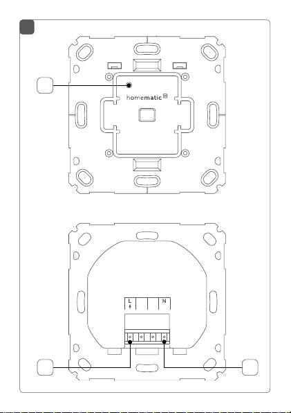
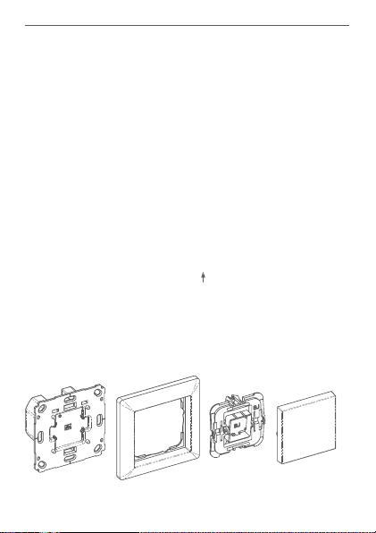
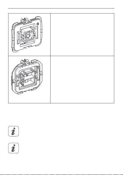
Geräteübersicht (s. Abbildung 1):
(A) Systemtaste (Anlerntaste und LED)
(B)
Anschlussklemme für L
(Außenleiter)
(C) Anschlussklemme für N (Neutralleiter)
Installationsübersicht
Homematic IP
Wandtaster
Beispiel für
vorhandenen Rahmen
Beispiel für
einen Adapter
Beispiel für
11
Page 12

Allgemeine Systeminformationen
4 Allgemeine Systeminformationen
Dieses Gerät ist Teil des Homematic IP Smart-HomeSystems und kommuniziert über das Homematic IP
Funkprotokoll. Alle Geräte des Systems können komfor
tabel und individuell per Smartphone über die HomematicIP App konfiguriert werden. Alternativ haben Sie die
eit, Homematic IP Geräte über die Homema-
Möglichk
tic Zentrale CCU2 oder in Verbindung mit vielen Partnerlösungen zu betreiben. Welcher Funktionsumfang
sich innerhalb des S
teren Komponenten ergibt, entnehmen Sie bitte dem
Homema
Dokumente und Updates finden Sie stets aktuell unter
www.eQ-3.de.
tic IP Anwenderhandbuch. Alle technischen
ystems im Zusammenspiel mit wei-
-
5 Adapter für Markenschalter
Um eine Kompatibilität mit möglichst vielen Herstellern
zu erreichen und eine Integration in die verschiedenen
Designs zu erleichtern, sind die nachfolgenden Wippadapter als Zubehör erhältlich. In Ausnahmefällen kann
eine Anpassung der Wippenhalterungen oder Rahmen der
verschiedenen Hersteller durch Sägen oder Feilen erforderlich sein.
*) Anpassen der Wippenhalterungen erforderlich.
**) Anpassen der Rahmen erforderlich.
12
Page 13
Adapter für Markenschalter
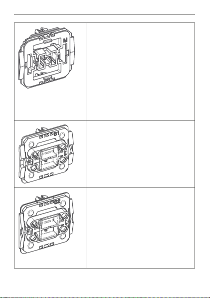
Adapter für Merten (M)
Atelier M
1-M
M-Plan
M-Plan Echtglas
M-Pure
M-Smart
M-ARC
M-Star
Atelier-Basis*)
M1 Basis*)
Adapter für Berker (B1)
Arsys
K.1
K.5
Adapter für Berker (B2)
S.1
Modul 2
B.1
B.3
B.7
Q.1
Q.3
Q.7
13
Page 14
Adapter für Markenschalter
14
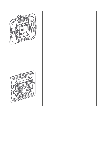
Adapter für Busch-Jaeger (BJ)
Busch-Duro 2000® SI
Busch-Duro 2000® SI Linear
Reflex SI
Reflex SI Linear
carat®
future® linear
solo®
Busch-axcent®
Busch-dynasty®
alpha
Busch-balance® SI
Adapter für Jung (J1)*)
LS 990
LS design
LS plus
CD 500
CD plus
Page 15
Adapter für Markenschalter
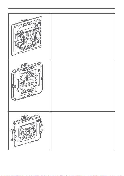
Adapter für Jung (J2)*)
A 500
A creation
A plus
AS 500
Adapter für Kopp (K)*) **)
Alaska
Athenis
Ambiente
Europa
Paris (Objekt HK 05)
Milano
Rivo
Cadiz
Venedig
Adapter für Gira (GD)
Standard
15
Page 16
Inbetriebnahme
Adapter für Gira 55 (G)
Standard 55
E2
Event
E22
ClassiX
E3
Esprit
Adapter für düwi / Popp (D)**)
Architaste
Arcada
Trend
Standard Quadro (Plus2000)
EverLuxe (Forever)
ProLuxe (Quadro)
PrimaLuxe
Eco
6 Inbetriebnahme
6.1 Installationshinweise
Bitte lesen Sie diesen Abschnitt erst vollständig,
bevor Sie mit der Installation beginnen.
Bitte notieren Sie sich vor der Installation die auf
dem Gerät angebrachte Gerätenummer (SGTIN)
und den Installationsort, damit Sie das Gerät im
Nachhinein leichter zuordnen können. Alternativ
16
Page 17

Inbetriebnahme
steht die Gerätenummer auch auf dem beiliegenden QRCode-Aufkleber.
Hinweis! Installation nur durch Personen mit
einschlägigen elektrotechnischen Kenntnissen
und Erfahrungen!*
Durch eine unsachgemäße Installation gefährden Sie
• Ihr eigenes Leben;
• das Leben der Nutzer der elektrischen Anlage.
Mit einer unsachgemäßen Installation riskieren Sie
schwere Sachschäden, z. B. durch Brand. Es droht für Sie
die persönliche Haftung bei Personen- und Sachschäden.
Wenden Sie sich an einen Elektroinstallateur!
Erforderliche Fachkenntnisse für die Installation:
*
Für die Installation sind insbesondere folgende Fachkenntnisse erforderlich:
• Die anzuwendenden „5 Sicherheitsregeln“:
Freischalten; gegen Wiedereinschalten sichern;
Spannungsfreiheit feststellen; Erden und Kurzschließen;
benachbarte, unter Spannung stehende Teile abdecken
oder abschranken;
• Auswahl des geeigneten Werkzeuges, der Messgeräte
und ggf. der persönlichen Schutzausrüstung;
• Auswertung der Messergebnisse;
• Auswahl des Elektro-Installationsmaterials zur Sicherstellung der Abschaltbedingungen;
• IP-Schutzarten;
17
Page 18

Inbetriebnahme
• Einbau des Elektroinstallationsmaterials;
• Art des Versorgungsnetzes (TN-System, IT-System,
TT-System) und die daraus folgenden Anschlussbedingungen (klassische Nullung, Schutzerdung, erforderliche
Zusatzmaßnahmen etc.).
Die Installation darf nur in handelsüblichen Schalterdosen (Gerätedosen) gemäß DIN 49073-1 erfolgen.
Das Gerät darf nur mit Adapter und einer zugehörigen, montierten Schalterabdeckung betrieben
werden. Die Schalterabdeckung darf nur während der Konfiguration entfernt werden.
Beachten Sie bei der Installation die Gefahrenhinweise gemäß „2 Gefahrenhinweise“ auf Seite 7.
Zugelassene Leitungsquerschnitte zum Anschluss an den
Wandtaster sind:
Starre Leitung
[mm2]
Flexible Leitung mit und ohne
Aderendhülse [mm2]
0,75 – 1,50 0,75 – 1,50
18
Page 19

Inbetriebnahme
6.2 Installation
Für die Installation des Wandtasters gehen Sie wie folgt vor:
Schritt 1 Schalten Sie die Leitungsschutzschalter
des Stromkreises ab.
Schritt 2 Ziehen Sie gegebenenfalls die Wippe vom
Rahmen des entsprechenden Schalters
ab. Ziehen Sie anschließend den Rahmen
mitsamt Klemm-/Haltestück vom Schalter
ab. Das Klemm-/Haltestück kann in
Abhängigkeit vom Hersteller transparent,
grau oder schwarz sein und hält den
Rahmen auf dem Schalter.
Um die Demontage zu erleichtern, kann
ein flacher spitzer Gegenstand, z. B. ein
Schlitzschraubendreher, zur Hilfe genommen werden.
Schritt 3 Lösen Sie die Befestigung des bestehen-
den Schalters und ziehen Sie den Schalter
vorsichtig aus der Unterputzdose.
Schritt 4 Lösen Sie die Verdrahtung und entfernen
Sie ggf. den vorhandenen Schalter.
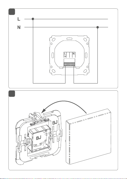
Schritt 5 Schließen Sie den Außenleiter an die An-
schlussklemme L (B) an (s. Abbildung 2).
Schritt 6 Schließen Sie den Neutralleiter an die An-
schlussklemme N (C) an (s. Abbildung 2).
19
Page 20

Inbetriebnahme
Schritt 7 Befestigen Sie den Wandtaster mittels
der mitgelieferten Schrauben an der
Unterputzdose. Bitte beachten Sie bei der
Montage, dass sich die Systemtaste (A)
des Aktors links oben befinden muss.
Schritt 8 Montieren Sie den Adapter auf der Wippe
(s. Abbildung 3).
Schritt 9 Befestigen Sie nun die Wippe inkl. Adapter
im Rahmen auf dem Aktor.
Platzieren Sie den Adapter dabei so, dass
die beiden Rasternasen in die vorhandenen Langlöcher passen (s. Abbildung 6).
Schritt 10 Schalten Sie die Leitungsschutzschalter
des Stromkreises wieder ein.
Schritt 11 Jetzt kann der Wandtaster an den Home-
matic IP Access Point angelernt werden
(s. „6.3 Anlernen“ auf Seite 21).
20
Page 21

Inbetriebnahme
6.3 Anlernen
Bitte lesen Sie diesen Abschnitt erst vollständig,
bevor Sie mit dem Anlernen beginnen.
Richten Sie zunächst Ihren Homematic IP Access
Point über die Homematic IP App ein, um weitere
Homematic IP Geräte im System nutzen zu können. Ausführliche Informationen dazu finden Sie
in der Bedienungsanleitung des Access Points.
Sie können das Gerät sowohl an den Access Point
als auch an die Homematic Zentrale CCU2 anlernen. Weitere Informationen dazu entnehmen Sie
bitte dem Homema
finden im Downloadbereich unter www.eQ-3.de).
Damit der Wandtaster in Ihr System integriert werden
und mit anderen Homematic IP Geräten kommunizieren
kann, muss er zunächst an den Homematic IP Access
Point angelernt werden.
Zum Anlernen des Wandtasters gehen Sie wie folgt vor:
• Önen Sie die Homematic IP App auf Ihrem
Smartphone.
• Wählen Sie den Menüpunkt „Gerät anlernen“ aus.
• Nach der Installation ist der Anlernmodus für 3
Minuten aktiv.
tic IP Anwenderhandbuch (zu
21
Page 22

Inbetriebnahme
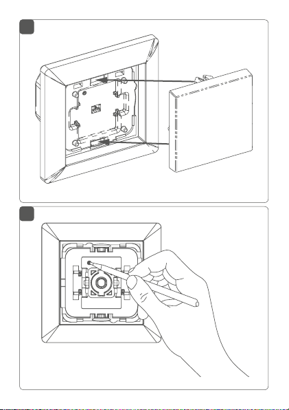
Sollte die Zeit bereits verstrichen sein, können Sie
den Anlernmodus manuell für weitere 3 Minuten
starten, indem Sie die Wippe entfernen und die
Systemtaste (A) kurz drücken (s. Abbildung 5).
• Das Gerät erscheint automatisch in der Homematic IP App.
• Zur Bestätigung geben Sie in der App die letzten
vier Ziern der Gerätenummer (SGTIN) ein oder
scannen Sie den QR-Code. Die Gerätenummer
finden Sie auf dem Aufkleber im Lieferumfang
oder direkt am Gerät.
• Warten Sie, bis der Anlernvorgang abgeschlossen
ist.
• Zur Bestätigung eines erfolgreichen Anlernvorgangs leuchtet die LED grün. Das Gerät ist nun
einsatzbereit.
• Leuchtet die LED rot, versuchen Sie es erneut.
• Wählen Sie aus, in welchen Anwendungen (z. B.
Licht und/oder Sicherheit) Sie Ihr Gerät verwenden möchten.
• Vergeben Sie in der App einen Namen für das Gerät und ordnen Sie es einem Raum zu.
22
Page 23

Fehlerbehebung
7 Fehlerbehebung
7.1 Befehl nicht bestätigt
Bestätigt mindestens ein Empfänger einen Befehl nicht,
leuchtet zum Abschluss der fehlerhaften Übertragung die
LED (A) rot auf. Grund für die fehlerhafte Übertragung kann
eine Funkstörung sein (s. „10 Allgemeine Hinweise zum
Funkbetrieb“ auf Seite 27). Die fehlerhafte Übertragung kann außerdem folgende Ursachen haben:
• Empfänger nicht erreichbar,
• Empfänger kann Befehl nicht ausführen (Lastausfall, mechanische Blockade etc.) oder
• Empfänger defekt.
7.2 Duty Cycle
Der Duty Cycle beschreibt eine gesetzlich geregelte Begrenzung der Sendezeit von Geräten im 868 MHz-Bereich. Das Ziel dieser Regelung ist es, die Funktion aller im
868 MHz-Bereich arbeitenden Geräte zu gewährleisten.
In dem von uns genutzten Frequenzbereich 868 MHz beträgt die maximale Sendezeit eines jeden Gerätes 1 % einer Stunde (also 36 Sekunden in einer Stunde). Die Geräte
dürfen bei Erreichen des 1 %-Limits nicht mehr senden,
bis diese zeitliche Begrenzung vorüber ist. Gemäß dieser
Richtlinie, werden Homematic IP Geräte zu 100 % normenkonform entwickelt und produziert.
Im normalen Betrieb wird der Duty Cycle in der Regel
nicht erreicht. Dies kann jedoch in Einzelfällen bei der Inbetriebnahme oder Erstinstallation eines Systems durch
23
Page 24

Fehlerbehebung
vermehrte und funkintensive Anlernprozesse der Fall sein.
Eine Überschreitung des Duty Cycle Limits wird durch ein
langes rotes Leuchten der LED (A) angezeigt und kann
sich durch temporär fehlende Funktion des Gerätes äußern. Nach kurzer Zeit (max. 1 Stunde) ist die Funktion des
Gerätes wiederhergestellt.
7.3 Fehlercodes und Blinkfolgen
Blinkcode Bedeutung Lösung
Kurzes oranges
Blinken
1x langes
grünes Leuchten
1x langes rotes
Leuchten
24
Funkübertragung/Sendeversuch/
Datenübertragung
Vorgang
bestätigt
Vorgang
fehlgeschlagen oder Duty
Cycle-Limit
erreicht
Warten Sie, bis die
Übertragung beendet ist.
Sie können mit der
Bedienung fortfahren.
Versuchen Sie es
erneut („7.1 Befehl
nicht bestätigt“ auf
Seite 23 oder „7.2
Duty Cycle“ auf Seite
23).
Page 25

Wiederherstellung der Werkseinstellungen
Kurzes oranges
Blinken (alle
10 s)
6x langes rotes
Blinken
1x oranges
und 1x grünes
Leuchten
Anlernmodus
aktiv
Gerät defekt Achten Sie auf die
Testanzeige Nachdem die Test-
Geben Sie die letzten vier Ziern der
Geräte-Seriennummer zur Bestätigung
ein (s. „6.3 Anlernen“
auf Seite 21).
Anzeige in Ihrer
App oder wenden
Sie sich an Ihren
Fachhändler.
anzeige erloschen
ist, können Sie
fortfahren.
8 Wiederherstellung der
Werkseinstellungen
Die Werkseinstellungen des Gerätes können wiederhergestellt werden. Dabei gehen alle Einstellungen verloren.
Um die Werkseinstellungen des Wandtasters wiederherzustellen, gehen Sie wie folgt vor:
• Entfernen Sie ggf. die Wippe (s. Abbildung 4).
25
Page 26

Wiederherstellung derWerkseinstellungen
• Drücken Sie für 4 s mit einem spitzen Gegenstand
(z. B. mit einem Stift) auf die Systemtaste (A), bis
die LED (A) schnell orange zu blinken beginnt (s.
Abbildung 5).
• Lassen Sie die Systemtaste wieder los.
• Drücken Sie die Systemtaste erneut für 4 s, bis die
LED grün aufleuchtet.
• Lassen Sie die Systemtaste wieder los, um das
Wiederherstellen der Werkseinstellungen abzuschließen.
Das Gerät führt einen Neustart durch.
Nach dem Neustart können Sie das Gerät wieder in Ihr
Homematic IP System integrieren.
26
Page 27

Wartung und Reinigung
9 Wartung und Reinigung
Das Gerät ist wartungsfrei. Überlassen Sie eine
Wartung oder Reparatur einer Fachkraft.
Reinigen Sie das Gerät mit einem weichen, sauberen,
trockenen und fusselfreien Tuch. Für die Entfernung
von stärkeren Verschmutzungen kann das Tuch leicht
mit lauwarmem Wasser angefeuchtet werden. Achten
Sie darauf, dass keine Feuchtigkeit in das Gerät gelangt.
Verwenden Sie keine lösemittelhaltigen Reinigungsmittel,
das Kunststogehäuse und die Beschriftung können dadurch angegrien werden.
10 Allgemeine Hinweise zum
Funkbetrieb
Die Funk-Übertragung wird auf einem nicht exklusiven
Übertragungsweg realisiert, weshalb Störungen nicht
ausgeschlossen werden können. Weitere Störeinflüsse
können hervorgerufen werden durch Schaltvorgänge,
Elektromotoren oder defekte Elektrogeräte.
Die Reichweite in Gebäuden kann stark von der
im Freifeld abweichen. Außer der Sendeleistung
und den Empfangseigenschaften der Empfänger
spielen Umwelteinflüsse wie Luftfeuchtigkeit neben baulichen Gegebenheiten vor Ort eine wichtige Rolle.
27
Page 28

Technische Daten
Hiermit erklärt die eQ-3 AG, Maiburger Str. 29, 26789
Leer, Deutschland, dass der Funkanlagentyp Homematic IP HmIP-BRC2 der Richtlinie 2014/53/EU entspricht.
Der vollständige Text der EU-Konformitätserklärung
ist unter der folgenden Internetadresse verfügbar:
www.eq-3.de
11 Technische Daten
Geräte-Kurzbezeichnung:
Versorgungsspannung: 230 V/50 Hz
Stromaufnahme: 10 mA max.
Leistungsaufnahme Ruhebetrieb: 0,2 W
Leitungsart und -querschnitt:
Installation: nur in Schalterdosen
Schutzart: IP20
Umgebungstemperatur: 5 bis 35 °C
Abmessungen (B x H x T): 71 x 71 x 37 mm
Gewicht: 47 g
Funk-Frequenzband: 868,0-868,6 MHz
869,4-869,65 MHz
Max. Funk-Sendeleistung: 10 dBm
Empfängerkategorie: SRD category 2
Typ. Funk-Freifeldreichweite: 240 m
Duty Cycle: < 1 % pro h/< 10 % pro h
28
HmIP-BRC2
starre und flexible Leitung,
0,75-1,5 mm²
gemäß DIN 49073-1
Page 29

Technische Änderungen vorbehalten.
Entsorgungshinweis
Gerät nicht im Hausmüll entsorgen! Elektronische Geräte sind entsprechend der Richtlinie
über Elektro- und Elektronik-Altgeräte über die
örtlichen Sammelstellen für Elektronik-Altgeräte
zu entsorgen.
Konformitätshinweis
Das CE-Zeichen ist ein Freiverkehrszeichen, das
sich ausschließlich an die Behörden wendet und
keine Zusicherung von Eigenschaften beinhaltet.
Bei technischen Fragen zum Gerät wenden Sie
sich bitte an Ihren Fachhändler.
Technische Daten
29
Page 30

Technische Daten
Package contents
Quantity Description
1 Homematic IP Remote Control for brand
2 Screws 3,2 x 15 mm
2 Screws 3,2 x 25 mm
1 Operating manual
Documentation © 2018 eQ-3 AG, Germany
All rights reserved. Translation from the original version in German. This manual may not be reproduced in any format, either in
whole or in part, nor may it be duplicated or edited by electronic,
mechanical or chemical means, without the written consent of
the publisher.
Typographical and printing errors cannot be excluded. However,
the information contained in this manual is reviewed on a regular
basis and any necessary corrections will be implemented in the
next edition. We accept no liability for technical or typographical
errors or the consequences thereof.
All trademarks and industrial property rights are acknowledged.
Printed in Hong Kong
Changes may be made without prior notice as a result of technical advances.
152005 (web)
Version 1.0 (01/2018)
30
switches – 2 channels
Page 31

Technische Daten
Table of contents
1 Information about this manual....................................32
2 Hazard information ........................................................32
3 Function and device overview ....................................36
4 General system information ........................................ 37
5 Adapters for brand switch systems ............................38
6 Start-up ............................................................................42
6.1 Installation instructions ..................................................... 42
6.2 Installation ............................................................................ 44
6.3 Teaching-in ..........................................................................46
7 Troubleshooting .............................................................47
7.1 Command not confirmed ..................................................47
7.2 Duty cycle ........................................................................... 48
7.3 Error codes and flashing sequences .............................. 49
8 Restore factory settings ............................................... 50
9 Maintenance and cleaning ........................................... 51
10 General information about radio operation ............. 51
11 Technical specifications ................................................53
31
Page 32

Information about this manual
1 Information about this manual
Please read this manual carefully before beginning
operation with your Homematic IP component. Keep the
manual so you can refer to it at a later date if you need to.
If you hand over the device to other persons for use,
please hand over this manual as well.
Symbols used:
Attention!
This indicates a hazard.
Please note:
This section contains important additional information.
2 Hazard information
Do not open the device. It does not contain any
parts that can be maintained by the user. There is
a risk of electric shock if the device is opened. If
you have any doubts, have the device checked by
an expert.
For safety and licensing reasons (CE), unauthorized change and/or modification of the device is
not permitted.
32
Page 33

Hazard information
Do not use the device if there are signs of damage
to the housing, control elements or connecting
sockets, for example. If you have any doubts,
have the device checked by an expert.
The device may only be operated in dry and dustfree environment and must be protected from
the eects of moisture, vibrations, solar or other
methods of heat radiation, cold and mechanical
loads.
The device is not a toy; do not allow children to
play with it. Do not leave packaging material lying
around. Plastic films/bags, pieces of polystyrene,
etc. can be dangerous in the hands of a child.
We do not assume any liability for damage to
property or personal injury caused by improper
use or the failure to observe the hazard
information. In such cases, any claim under
warranty is extinguished! For consequential
damages, we assume no liability!
The device may only be used for fixed installations.
The device must be securely attached within a
fixed installation.
33
Page 34

Hazard information
The actuator is part of the building installation.
The relevant national standards and directives
must be taken into consideration during planning
and set-up. The device has been designed solely
for operation on a 230V/50 Hz AC supply. Only
qualified electricians (to VDE 0100) are permitted
to carry out work on the 230 V mains. Applicable
accident prevention regulations must be complied with whilst such work is being carried out.
To avoid electric shocks from the device, please
disconnect the
circuit-breaker).
mains voltage (trip the miniature
Noncompliance with the installation instructions can cause fire or introduce
other hazards.
When connecting to the device terminals, take
the permissible cables and cable cross sections
into account.
34
Page 35

Hazard information
The circuit to the which the device will be
connected has to be secured by a cable
protection switch in accordance with EN60898-1
(tripping characteristic B or C, max. 16 A rated
current, min. 6 kA interrupting rating, energy
limiting class 3). Installation regulations according
to VDE 0100 and HD382 or 60364 have to be
considered. Users must be able to easily access
the cable protection switch. This must be marked
as disconnecting device for the actuator.
Before the actuator is connected, remove the
fuse from the fuse box
.
Except for configuration, the device may only be
operated with an associated switch cover.
The device may only be operated within residential buildings.
Using the device for any purpose other than that
described in this operating manual does not fall
within the scope of intended use and shall invalidate any warranty or liability.
35
Page 36

Function and device overview
3 Function and device overview
The Homematic IP Remote Control for brand switches is
used to control other Homematic IP devices and functions via a push-button rocker. At the push of a button,
the eco mode f
are switched on and o or the panic light of a security
solution is switched.
The device is installed into empty flush-mounted boxes
or replaces already existing switches, if a phase as well as
a neutral conductor are available in the flush-mounted
box.
Adapters for dierent switches allow you to replace
switches made by popular manufacturers in a cost-effective way. Using the components of existing or planned
switches and cabling r
minimum. The design, colour and finish of switches that
have already been installed does not change, since the
existing frames and rockers can continue to be used.
Device overview (see fig. 1):
or the heating system is activated, lights
educes the installation costs to a
(A) System button (teach-in button and LED)
(B)
Connecting terminal L
(C) N (neutral conductor) connecting terminal
36
(phase conductor)
Page 37

General system information
Installation overview
Homematic IP
Remote Control
Example for
existing frame
Example for
adapter
Example for
existing rocker
4 General system information
This device is part of the Homematic IP smart home
system and works with the Homematic IP radio protocol. All devices of the system can be configured
fortably and individually with the Homematic IP
com
smartphone app. Alternatively, you can operate the
Homematic IP devices via the Homematic Central
Control Unit CCU2 or in connection with various part
ner solutions. The available functions provided by the
system in combina
tion with other components are
described in the Homematic IP User Guide. All cur
rent technical documents and updates are provided at
www.eQ-3.com.
-
-
37
Page 38

Adapters for brand switch systems
5 Adapters for brand switch systems
In order to achieve compatibility with as many manufacturers as possible and make integration in the dierent
designs easier, the following rocker adapters are available
as accessories. In exceptional cases the rocker holders or
frames from the dierent manufacturers may need to be
sawn or filed for adaptation purposes.
*) Rocker holder adaptation required
**) Frame adaptation required.
Adapter for Merten (M)
Atelier M
1-M
M-Plan
M-Plan Echtglas
M-Pure
M-Smart
M-ARC
M-Star
Atelier-Basis*)
M1 Basis*)
38
Page 39

Adapters for brand switch systems
Adapter for Berker (B1)
Arsys
K.1
K.5
Adapter for Berker (B2)
S.1
Modul 2
B.1
B.3
B.7
Q.1
Q.3
Q.7
Adapter for Busch-Jaeger (BJ)
Busch-Duro 2000® SI
Busch-Duro 2000® SI Linear
Reflex SI
Reflex SI Linear
carat®
future® linear
solo®
Busch-axcent®
Busch-dynasty®
alpha
Busch-balance® SI
39
Page 40

Adapters for brand switch systems
Adapter for Jung (J1)*)
LS 990
LS design
LS plus
CD 500
CD plus
Adapter for Jung (J2)*)
A 500
A creation
A plus
AS 500
Adapter for Kopp (K)*) **)
Alaska
Athenis
Ambiente
Europa
Paris (Objekt HK 05)
Milano
Rivo
Cadiz
Venedig
40
Page 41

Adapters for brand switch systems
Adapter for Gira (GD)
Standard
Adapter for Gira 55 (G)
Standard 55
E2
Event
E22
ClassiX
E3
Esprit
Adapter for düwi / Popp (D)**)
Architaste
Arcada
Trend
Standard Quadro (Plus2000)
EverLuxe (Forever)
ProLuxe (Quadro)
PrimaLuxe
Eco
41
Page 42

Start-up
6 Start-up
6.1 Installation instructions
Please read this entire section before starting to
install the device.
Before installation, please note the device number (SGTIN) labelled on the device as well as the
exact installation location in order to make later
allocation easier. You can also find the device
number on the QR code sticker supplied.
Please note! Only to be installed by persons with
the relevant electro-technical knowledge and
experience!*
Incorrect installation can put
• your own life at risk;
• and the lives of other users of the electrical system.
Incorrect installation also means that you are running the
risk of serious damage to property, e.g. because of a fire.
You may be personally liable in the event of injuries or
damage to property.
42
Page 43

Start-up
Contact an electrical installer!
Specialist knowledge required for installation:
*
The following specialist knowledge is particularly important during
installation:
• The “5 safety rules” to be used:
Disconnect from mains; Safeguard from switching on
again; Check that system is deenergised; Earth and short
circuit; Cover or cordon o neighbouring live parts;
• Select suitable tool, measuring equipment and, if necessary, personal safety equipment;
• Evaluation of measuring results;
• Selection of electrical installation material for safeguarding shut-o conditions;
• IP protection types;
• Installation of electrical installation material;
• Type of supply network (TN system, IT system, TT system) and the resulting connecting conditions (classical
zero balancing, protective earthing, required additional
measures etc.).
Installation may only take place in normal
commercial switch boxes (device boxes) in
accordance with DIN 49073-1.
The device may only be operated with adapters
and an associated, fitted switch cover. The switch
cover may only be removed during configuration.
Please observe the hazard information in section
“2 Hazard information” on page 32
.
stallation
during in-
43
Page 44

Start-up
Permitted cable cross sections for connecting to the
wall-mount remote control are:
rigid cable [mm2] flexible cable with/without
ferrule [mm2]
0.75 – 1.50 0.75 – 1.50
6.2 Installation
To install the wall-mount remote control, please proceed
as follows:
Step 1 Switch o the circuit breaker of the
Step 2 If necessary, pull the rocker o the frame
Step 3 Loosen the fastening of the existing
44
power circuit.
of the relevant switch. Then pull the
frame o the switch together with the
clamping/retaining piece. The clamping/
retaining piece can be transparent, grey
or black depending on the manufacturer,
and holds the frame onto the switch.
To make removal easier, a flat, pointed
object such as a slotted screwdriver can
be used.
switch and carefully remove it from the
flush-mounted box.
Page 45

Start-up
Step 4 Release the wiring and remove the exist-
ing switch if necessary.
Step 5 Connect the phase conductor to con-
necting terminal L (B) (see fig. 2).
Step 6 Connect the neutral conductor to con-
necting terminal N (C) (see fig. 2).
Step 7 Secure the wall-mount remote control
using the provided screws into the
flush-mounted box. Please note that the
system button (A) of the actuator must be
at the top left during installation.
Step 8 Fit the adapter to the rocker (see fig. 3).
Step 9 Now secure the rocker with the adapter
in the frame on the actuator.
Position the adapter so that both latching
lugs fit into the existing elongated holes
(see fig. 6).
Step 10 Switch the circuit breaker of the power
circuit back on again.
Step 11 Now, the wall-mount remote control
can be connected to the Homematic IP
Access Point (see “11.1 Teaching-in” on
page <ÜS>).
45
Page 46

Start-up
6.3 Teaching-in
Please read this entire section before starting
the teach-in procedure.
First set up your Homematic IP Access Point via
the Homematic IP app to enable operation of
other Homematic IP devices within your system.
For further information, please refer to the operating manual of the Access Point.
You can connect the device either to the Access
Point or to the Homematic Central Control Unit
CCU2. For detailed information, please refer to
the Homematic IP User Guide, available for down
load in the download area of www.eQ-3.com.
To integrate the wall-mount remote control into your
system and enable it to communicate with other Homematic IP devices, you must connect the device to your
Homematic IP Access Point first.
To teach-in the wall-mount remote control, please proceed as follows:
• Open the Homematic IP app on your smartphone.
• Select the menu item “Teach-in device”.
• After installation, the teach-in mode remains activated for 3 minutes.
46
-
Page 47

Troubleshooting
If the time has exceeded, you can manually restart the teach-in mode for another 3 minutes by
removing the rocker and pressing the system
button (A) shortly (see fig. 5).
• Your device will automatically appear in the
Homematic IP app.
• To confirm, please enter the last four digits of the
device number (SGTIN) in your app or scan the
QR code. Therefore, please see the sticker supplied or attached to the device.
• Please wait until teach-in is completed.
• If teaching-in was successful, the LED lights up
green. The device is now ready for use.
• If the LED lights up red, please try again.
• Please select, in which application (e.g. light and/
or security) you would like to use the device.
• In the app, give the device a name and allocate
it to a room.
7 Troubleshooting
7.1 Command not confirmed
If at least one receiver does not confirm a command, the
device LED (A) lights up red at the end of the failed transmission process. The failed transmission may be caused
by radio interference (see “10 General information about
radio operation” on page 51). The failed transmission
47
Page 48

Troubleshooting
may also be caused by the following:
• Receiver cannot be reached.
• Receiver is unable to execute the command (load
failure, mechanical blockade, etc.).
• Receiver is defective.
7.2 Duty cycle
The duty cycle is a legally regulated limit of the transmission time of devices in the 868 MHz range. The aim of
this regulation is to safeguard the operation of all devices
working in the 868 MHz range.
In the 868 MHz frequency range we use, the maximum
transmission time of any device is 1% of an hour (i.e. 36
seconds in an hour). Devices must cease transmission
when they reach the 1% limit until this time restriction
comes to an end. Homematic IP devices are designed
and produced with 100% conformity to this regulation.
During normal operation, the duty cycle is not usually
reached. However, repeated and radio-intensive teachin processes mean that it may be reached in isolated instances during start-up or initial installation of a system.
If the duty cycle is exceeded, this is indicated by one long
red lighting of the device LED (A), and may manifest itself
in the device temporarily working incorrectly. The device
starts working correctly again after a short period (max.
1 hour).
48
Page 49

Troubleshooting
7.3 Error codes and flashing sequences
Flashing code Meaning Solution
Short orange
flashing
1x long green
lighting
1x long red
lighting
Short orange
flashing (every
10 s)
6x long red
flashing
Radio
transmission/
attempting to
transmit/data
transmission
Transmission
confirmed
Transmission
failed or duty
cycle limit is
reached
Teach-in
mode active
Device defective
Wait until the
transmission is
completed.
You can continue
operation.
Please try again (see
sec. “7.1 Command
not confirmed” on
page 47 or “7.2
Duty cycle” on page
48).
Please enter the last
four numbers of the
device serial number
to confirm (see “6.3
Teaching-in” on
page 46).
Please see your app
for error message or
contact your retailer.
49
Page 50

Restore factory settings
1x orange and 1
x green lighting
Test display Once the test
display has stopped,
you can continue.
8 Restore factory settings
The factory settings of the device can be restored. If you do this, you will lose all your settings.
To restore the factory settings of the wall-mount remote
control, please proceed as follows:
• Remove the rocker if required (see fig. 4).
• Press and hold down the system button (A) for 4
seconds with a pointed object (e.g. a pen) until the
LED (A) starts flashing orange quickly (see fig. 5).
• Release the system button again.
• Press and hold down the system button again for
4 seconds, until the LED lights up green.
• Release the system button to finish the procedure.
The device will perform a restart. After the restart, you
can again integrate your device into your Homematic IP
system.
50
Page 51

Maintenance and cleaning
9 Maintenance and cleaning
The product does not require any maintenance.
Enlist the help of an expert to carry out any maintenance or repairs.
Clean the device using a soft, lint-free cloth that is clean
and dry. You may dampen the cloth a little with lukewarm
water in order to remove more stubborn marks. Make
sure that no moisture will ingress into the housing. Do
not use any detergents containing solvents, as they could
corrode the plastic housing and label.
10 General information about radio
operation
Radio transmission is performed on a non-exclusive
transmission path, which means that there is a possibility of interference occurring. Interference can also be
caused by switching operations, electrical motors or defective electrical devices.
The range of transmission within buildings can
dier greatly from that available in the open air.
Besides the transmitting power and the reception
characteristics of the receiver, environmental
factors such as humidity in the vicinity have an
important role to play, as do on-site structural/
screening conditions.
51
Page 52

General information about radio operation
Hereby, eQ-3 AG, Maiburger Str. 29, 26789 Leer/Germany
declares that the radio equipment type Homematic IP
HmIP-BRC2 is in compliance with Directive 2014/53/
EU. The full text of the EU declaration of conformity
is available at the following internet address:
www.eq-3.com
52
Page 53

Technical specifications
11 Technical specifications
Device short description:
Supply voltage: 230 V/50 Hz
Current consumption: 10 mA max.
Standby power
consumption: 0.2 W
Cable type and cross section:
Installation: only in normal com-
Degree of protection: IP20
Ambient temperature: 5 to 35 °C
Dimensions (W x H x D): 71 x 71 x 37 mm
Weight: 47 g
Radio frequency band: 868.0-868.6 MHz
869.4-869.65 MHz
Maximum radiated power: 10 dBm
Receiver category: SRD category 2
Typ. open area RF range: 240 m
Duty cycle: < 1 % per h/< 10 % per h
Subject to technical changes.
HmIP-BRC2
rigid and flexible cable,
0.75-1.5 mm²
mercial switch boxes in
accordance with DIN
49073-1
53
Page 54

Technical specifications
Instructions for disposal
Do not dispose of the device with regular domestic waste! Electronic equipment must be disposed of at local collection points for waste electronic equipment in compliance with the Waste
Electrical and Electronic Equipment Directive.
Information about conformity
The CE sign is a free trading sign addressed exclusively to the authorities and does not include
any warranty of any properties.
For technical support, please contact your retailer.
54
Page 55

Kostenloser Download der Homematic IP App!
Free download of the Homematic IP app!
Bevollmächtigter des Herstellers:
Manufacturer’s authorised representative:
eQ-3 AG
Maiburger Straße 29
26789 Leer / GERMANY
www.eQ-3.de
 Loading...